Automatic Generation of Sound Synthesis Techniques
by
Ricardo A. Garcia
B.S., Electrical Engineering (1996)
Universidad Pontificia Bolivariana
M.S., Music Engineering Technology (1999)
University of Miami
Submitted to the Program in Media Arts and Sciences,
School of Architecture and Planning,
in partial fulfillment of the requirements for the degree of
Master of Science in Media Arts and Sciences
at the
MASSACHUSETTS INSTITUTE OF TECHNOLOGY
September 2001
@ Massachusetts Institute of Technology 2001. All Rights Reserved
Author
Ricardo A. Garcia
Program in Media Arts and Sciences
August 21, 2001
Certified by
-
I.-1A~
Barry L. Vercoe
Professor of Media Arts and Sciences
Thesis Supervisor
Accepted by
Dr. Andrew B. Lippman
Chair, Departmental Committee on Graduate Students
Program in Media Arts and Sciences
MASSACHUSEUS IN ITUTFOF TECHNOLOGY
ROTCH
OCT
12 2001
Automatic Generation of Sound Synthesis Techniques
byRicardo A. Garcia
Submitted to the Program in Media Arts and Sciences, School of Architecture and Planning,
on August 21, 2001, in partial fulfillment of the requirements for the degree of
Master of Science in Media Arts and Sciences
ABSTRACT
Digital sound synthesizers, ubiquitous today in sound cards, software and dedicated hardware, use algorithms (Sound Synthesis Techniques, SSTs) capable of generating sounds similar to those of acoustic instruments and even totally novel sounds.
The design of SSTs is a very hard problem. It is usually assumed that it requires human ingenuity to design an algorithm suitable for synthesizing a sound with certain characteristics. Many of the SSTs commonly used are the fruit of experimentation and a long refinement processes.
A SST is determined by its "functional form" and "internal parameters". Design of SSTs is usually done by selecting a fixed functional form from a handful of commonly used SSTs, and performing a parameter estimation technique to find a set of internal parameters that will best emulate the target sound.
A new approach for automating the design of SSTs is proposed. It uses a set of examples of the desired behavior of the SST in the form of "inputs + target sound". The approach is capable of suggesting novel functional forms and their internal parameters, suited to follow closely the given examples.
Design of a SST is stated as a search problem in the SST space (the space spanned by all the possible valid functional forms and internal parameters, within certain limits to make it practical). This search is done using evolutionary methods; specifically, Genetic Programming (GP). A custom language for representing and manipulating SSTs as topology graphs and expression trees is proposed, as well as the mapping rules between both representations. Fitness functions that use analytical and perceptual distance metrics between the target and produced sounds are discussed. The AGeSS system (Automatic Generation of Sound Synthesizers) developed in the Media Lab is outlined, and some SSTs and their evolution are shown.
Thesis Supervisor: Barry L. Vercoe
Automatic Generation of Sound Synthesis Techniques
by
Ricardo A. Garcia
Thesis Reader
Dr. Joseph A. Paradiso Principal Research Scientist MIT Media Laboratory
Thesis Reader
Dr. Una-May O'Reilly Research Scientist MIT Artificial Intelligence Laboratory
ACKNOWLEDGMENTS
This thesis leaves more unsolved questions than answers. That was the goal: to immerse myself in the problem that I chose, and to find out that there are still many things that have to be explored. But during the process of understanding the problems and proposing solutions, I learned, and learned things well.
The most important thing that I have learned during my time at MIT is that there are more things to be explored and solved in the world than I used to believe. We are just starting to understand this world, and we are now capable of even creating new worlds of knowledge that claim to be studied.
There are many people and institutions that have contributed in some way to my personal growth and the development of this research:
- MIT Media Lab and the Digital Life consortium, for giving to me the opportunity and the means to do this research.
- My advisor, Barry Vercoe and the past and present members of the Machine Listening Group, for their example
- Paris Smaragdis for encouraging me to defy the world, even though the consequences are strong.
- Youngmoo Kim, for his support in the analysis by synthesis ideas.
- Wei Chai, my officemate, for supporting my music, phone talks, and jokes!
- Rebecca Reich for her role of technical editor in the final manuscript, and counselor in tough times.
- Connie, Elizabeth and Orla, that helped me to not to go crazy (crazier) with so many details in life!
- My thesis reader, Joe Paradiso, for his inspiring comments
- My thesis reader, Una-May O'Reilly, who I consider a great advisor, not just for the enormous guidance with evolutionary computation; but specially for her support in this complex fitness landscape called student life.
- Professor Withman Richards, for his ideas about models, structures and representations. The original idea for this thesis started as a project for his class.
- My friends at MIT and Boston, those who have shared good and bad times with me.
- My classmates and friends at University of Miami: keep trying to take over the world with our music engineering.
- Professor Ken Pohlmann, for his insightful guidance.
- My professors at Universidad Pontificia Bolivariana in Medellin, Colombia; for nourishing my beliefs that audio is high-level engineering.
Special dedications in Spanish:
- A mis padres, que me enseiaron a soh-ar, y a luchar fuertemente por alcanzar mis suefnos.
- A mi familia, que siempre ha estado conmigo, asi la distancia nos separe.
- A mis amigos, que siempre sofiamos en hacer cosas grandes, y hoy, hacemos cosas grandes que nos permiten sofiar.
- A aquellos amores que, asi sea por un solo instante, llenaron mi vida; y por los amores que seguirin inspirindome.
- Dedico esta tesis a todos aquellos que saben que la musica es magia que llena y eleva el espiritu; y cada cosa que hacemos por elevar el espiritu tiene un poco de divino.
- Tambi6n, un aplauso por las arepitas de ch6colo con quesito, especialmente si son de un rancherito en las palmas.
TABLE OF CONTENTS
ABSTRACT ... 3
A CKN OW LED GM EN TS ... 7
TABLE OF CO N TEN TS... 9
1 IN TR O D U CTIO N ... 13
1.1 CON TRIBU TION S... 13
1.2 M OTIVATION... 13
1.3 BACKGROUND AND RELATED W ORK... 14
1.4 APPROACH ... 15
2 SOUND SYNTHESIS TECHNIQUES (SST)... 17
2.1 SOUND SYNTHESIS ... 17
2.1.1 Algorithm s...
17
2.1.2 Functional form and internal param eters: ... ... ... 17
2.1.3 Inputs and outputs: ... 18
2.2 LANGUAGE AND REPRESENTATION ... 18
2.2.1 Instruction list (pseudocode) and form ulas: ... 18
2.2.2 Topology graph (flow diagram ): ... 19
2.2.3 Equivalence in representations: ... 20
2.3 "CLASSIC" SOUND SYNTHESIS TECHNIQUES:... 20
2.3.1 Additive techniques:... 21
2.3.1.1 Fourier: ... 21
2.3.1.2 Peak Tracking and Spectral Modeling Synthesis: ... ... 22
2.3.1.3 Sampling, M ultiple wavetable, wavestacking:... 23
2.3.2 Subtractive M ethods: ... 25
2.3.2.1 Vocoders:...25
2.3.2.2 Linear Predictive Coding (LPC)) synthesis ... 26
2.3.3 M odulation M ethods:... 26
2.3.3.1 Amplitude M odulation (AM ) and Ring M odulation (RM ):... 26
2.3.3.2 Frequency M odulation (FM ): ... 27
2.3.3.3 W aveshaping: ... 27
2.3.4 Physical M odeling: ... 28
2.3.4.1 W aveguides: ... 28
2.3.4.2 Difference equations:...28
2.3.5 Sum m ary of functional elem ents ... 29
3 DESIGN OF SOUND SYNTHESIS TECHNIQUES... 31
3.1 D ESIGN:... 31
3.1.1 Specifications of design for SSTs:... 31
3.1.2 Inputs ... 31
3.1.3 Outputs (TARGET) ... 31
3.1.4 Error m etric ... 31
3.1.5 Implem entation/algorithm ic constraints:... 32
3.2 PROPOSED APPROACH FOR DESIGN OF SSTS... 32
3.2.1 Classic design ... 32
3.2.2 Proposed approach for design... 33
3.3 PARAM ETER ESTIM ATION... 33
3.3.1 M athem atical analysis:... 34
3 .3 .2 .1 P aram eter sp ace : ... 3 5
3.3.2.2 Fitness Function (error function): ... 35
3 .3 .2 .3 E n u m eratio n : ... 3 6 3.3.2.4 Gradient descent, simplex, downhill:... 36
3.3.2.5 Simulated Annealing: ... 36
3.3.2.6 Evolutionary methods:...36
3.4 DESIGN AS A SEARCH IN THE TOPOLOGY SPACE ... 37
3.4.1 Automated functional-form suggestion mechanism ... 37
3.4.2 SST space:... 38
3.4.3 Hypothesis: ... 38
3.4.4 D esign as a Search: ... 38
3.4.5 Size of the SST space: ... 38
3.4.6 Design as a search:... 39
3.4.6.1 Searching the SST space:...39
4 SEARCH IN G TH E SST SPA CE ... 41
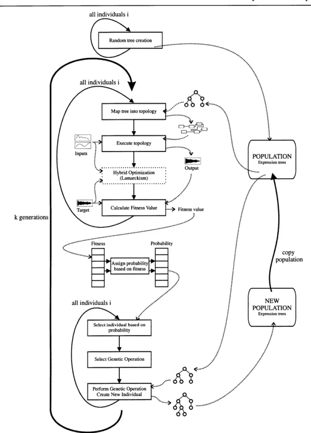
4.1 GENETIC PROGRAMMING ... 41
4.1.1 The genetic programm ing loop:... ... 41
4.1.2 About the individuals, populations and candidate solutions: ... 42
4.1.3 Execution and evaluation... 44
4.2 SST SPACE: TOPOLOGIES AND FUNCTIONAL ELEMENTS ... 45
4.2.1 Sound Synthesis Engines (SSE) ... 45
4.2.2 Proposed Topology Graph: Compatible Blocks ... 46
4.3 MAPPING EXPRESSION TREES TO TOPOLOGY GRAPHS: ... ... 47
4.3.1 Background: ... 48
4.3.1.1 Automated Synthesis of Analog Electrical Circuits: ... ... 48
4.3.1.2 Cellular Encoding of Genetic Neural Networks: ... 48
4.3.2 Proposed M apping... 49
4.3.2.1 Development process:...50
4.3.2.2 A simple repertoire of topology developing functions: ... ... 50
4.4 INTRODUCING HYBRID-OPTIMIZATION: LAMARCKIAN EVOLUTION ... .... 51
4.5 FITNESS FUNCTIONS ... 53
4.5.1 Analytical vs Perceptual:... 53
4.5.2 Analytical FF: Least Squared Error (LSE) ... 53
4.5.3 Perceptual FF: Simultaneous Frequency Masking (SFM) ... 55
5 DEVELO PED SYSTEM ... 59
5 .1 U SE R : ... 5 9 5.1.1 Inputs:... 59 5.1.2 Output:... 60 5.2 SOFTW ARE: ... 60 5.2.1 Tree manipulation: ... 62 5.2.2 Topology:... 62 5.2.3 Fitness
function:
... 625.2.4 Genetic Programm ing Loop: ... ... 62
5.2.5 Edition and visualization: ... 62
6 EXPERIM EN TA TIO N AND RESULTS... 65
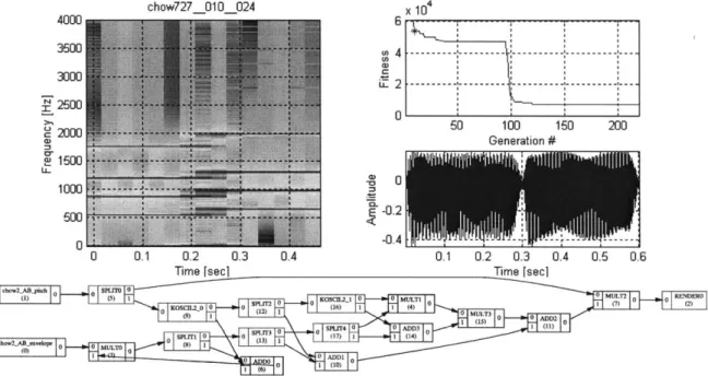
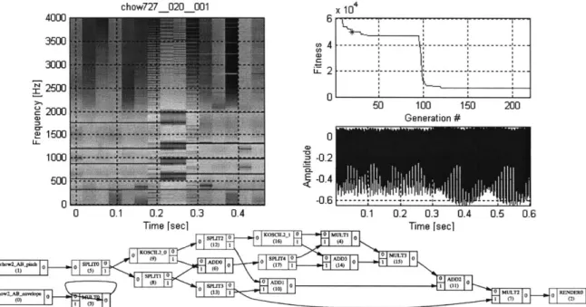
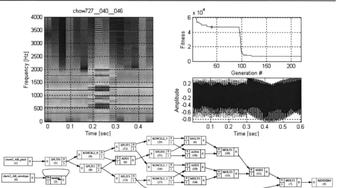
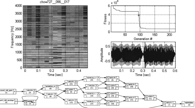
6.1 EXPERIMENT 1. FM SYNTHESIS (CHow727)... 65
6.1.1 Selection of a target SST:... 65
6.1.2 Inputs/target: ... 65
6.1.3 Fitness
function:
... 666.1.4 AGeSS param eters:... 66
6.1.5 Analysis of best of generation individuals: ... ... ... 67
6.1.6 Functional form analysis. ... 76
6.2 EXPERIM ENT 2. FM SYNTHESIS (CHow 727B)... 78
6.2.1 Selection of a target SST:... 78
6.2.2 Inputs/target: ... 78
6.2.3 Fitness Function:... 78
6.2.4 AGeSS param eters:... 79
6.2.5 Analysis of best of generation individuals: ... 79
6.3 EXPERIM ENT 3. PIANO (DES44) ... 83
6.3.1 Selection of a target SST:... 83
6.3.2 Inputs/target: ... 84
6.3.3 Fitness Function:... 84
6.3.4 AG eSS param eters:... 84
6.3.5 Analysis of best of generation individuals: ... ... ... 84
6.4 SUM M ARY OF EXPERIM ENTS... 86
7 C O N CLU SIO N S ... 87
7.1 FU TU RE D IRECTION S... 88
8 A PPEND IX ... 91
8.1 SYNTAX RULES FOR EXPRESSION TREES ... 91
8.2 SOUND SYNTHESIS ENGINE ... 94
9 R EFER EN CES... 97
Automatic Generation of Sound Synthesis Techniques
1 INTRODUCTION
1.1
CONTRIBUTIONS
This thesis describes the concepts needed to develop an approach for automating the design of Sound Synthesis Techniques (SSTs). Key ideas introduced with this research include:
A custom developmental representation of a Sound Synthesis Technique: Sound synthesis Techniques are usually represented as topology graphs (cyclic graphs). A mapping from an expression tree (acyclic graph) that encodes the "development" of an embryonic topology is proposed and used. This representation allows easy management and manipulation of SSTs, especially when used in conjunction with evolutionary methods.
Design as a search in the SST space: The space spanned by all the possible functional forms and internal parameters for SSTs is introduced. Design is treated as a search in the SST space.
Evolutionary methods to search the SST space: The advantage of using evolutionary methods to search the SST space is analyzed. A Genetic Programming technique is outlined and used as the core search method in the developed system.
Analytical and perceptual fitness Functions: The performance of suggested SSTs is measured using custom fitness functions. Two analytical and one perceptual fitness function are suggested and used.
Automatic Generation of Sound Synthesizers (AGeSS) system: A set of computer programs and scripts termed AGeSS was developed to show an empirical proof of the concepts introduced in this research. Different experiments and their results are outlined.
1.2
MOTIVATION
In a very general sense, a sound synthesizer is regarded as any device capable of producing sound. Digital computers can be used to produce digital sound samples using digital to analog converters (DAC). In electronic music parlance, a digital sound synthesizer is an algorithm implemented in a digital computer, with the goal of producing digital sound samples (waveforms). These algorithms for sound generation are termed Sound Synthesis Techniques (SSTs).
An SST can be decomposed into a functional form and internal parameters. The functional form describes the relationship between the functions and elements in the algorithm, while the internal parameters are variables that take a particular value at the moment of implementation of the algorithm (depending on the desired behavior). SSTs are usually represented using instruction lists or topology graphs (flow diagrams). "Classic" SSTs are a set of algorithms that have been used through the years in digital and analog synthesizers for emulating the sound of classical instruments, or to create totally novel sounds. Some of them have been studied in depth by researchers and musicians.
Design of a SST is customarily limited to the selection of a functional form from a set of algorithms (i.e. "classic" SSTs) followed by application of a mathematical technique for estimation of the internal parameters to match a target sound. The design of SSTs, more specifically their functional form, is a very hard problem. It is usually assumed that it requires human ingenuity to design an algorithm suitable for synthesizing sound with certain characteristics. Many of the SSTs commonly used are the fruit of experimentation and a long refinement processes.
The design of a SST is driven by the design specifications. They usually include a desired configuration for the number and type of inputs, some kind of error metric to measure the performance of the SST, and some implementation considerations (i.e. complexity of the algorithm). One of the most important aspects in design of a SST is the number and type of inputs. Some SST algorithms perform well in theory, but require a high amount of control information that makes them not very practical. Also, the meaning of the inputs plays an important role when using a SST. It makes more sense to use inputs related to "real world" parameters like brightness, or depth, than more obscure and difficult to understand parameters.
Our goal is to propose a general approach capable of suggesting valid functional forms and internal parameters for a SST to synthesize a target sound, using a known set of inputs (time varying signals). This problem is related to the system identification, or symbolic regression problem stated in control theory. The inputs and outputs of the system are known, but the system
is unknown.
1.3
BACKGROUND AND RELATED WORK
Horner et al. (Horner, Beauchamp et al. 1993) proposed an approach for automating the internal parameter estimation of FM synthesizers using evolutionary methods, in particular Genetic Algorithms (GA). Before this approach, the selection of parameters for FM synthesizers was usually realized by trial and error, using some analysis methods to compare (by a human) the sounds produced by the synthesizer and the target. The goal of the algorithm is to find parameters for a fixed functional form synthesis technique (single modulator, multiple carriers FM synthesis) to match the spectrum of a target sound with harmonic partials. The search for the parameters was done using a genetic algorithm, that represented them as a fixed length bitstring, and using genetic operations it was possible to explore the parameter-space of the problem.
A fitness metric that calculated the Least Squared error between the magnitude spectrums of the output and target sounds was used. This measure was performed in selected frames across the duration of the sound, usually with more frames in the attack section.
This research is of relevance to us in indicating the possibilities of using evolutionary methods for exploring complex spaces; more specifically, sound spaces. The fitness metric proposed is also of interest for us. It was the original fitness function used in the first stages of our research. Also, this study shows in an indirect way the limitations when using a single functional-form when designing SSTs.
Johnson (Johnson 1999) proposed an interesting approach to use evolutionary methods and human listeners in an interactive system to explore the parameter space of (Fonction d'Onde Formantique) FOF synthesis. In his research, he proposes an interactive interface that lets the
Automatic Generation of Sound Synthesis Techniques
user select the "best" synthesizers from a population, and the system "proposes" new individuals for the next population. This approach proved to be efficient for problems involving the estimation of many complex parameters (FOF synthesis has many non-intuitive parameters to explore).
Wehn (Wehn 1998) has an approach that includes part of the functional form of the synthesis techniques in the search space. His approach describes a set of basic functional elements (noise, sinusoid, filter) and a connection matrix that 'will ultimately outline the functional form of the synthesizers. The fitness function is similar to the one used by Homer. A GA is used to explore the connections and their weights between elements. In part, the goals of When's research are shared with our research, but the methodology is very different. The representation of the problems is the main difference, followed by the type of manipulations done to the individuals and the usage of the fitness functions.
1.4
APPROACH
For us, the space of the SSTs is defined as the space of all the possible combinations of a given set of functional elements and their connections. Design of a SST is regarded as a search in the SST space. The goal is to "find" a point in the SST space that minimizes the error in the fitness function, and therefore, satisfies the specifications of design. Points in the SST space define a functional form and internal parameters for a specific SST.
The search in this space is performed using a class of evolutionary computation method called Genetic Programming (GP). GP has shown outstanding empirical performance in searching complex multidimensional spaces (Koza 1992; Koza 1994; Koza 1999).
Custom SST representations in the form of topology graphs and expression trees are developed along with their required mapping rules. Topology graphs are the most widely used representation for SST, but they are difficult to manipulate. Expression trees facilitate the level of manipulation required to use GP for exploring the SST space.
Different types of fitness functions are analyzed, and a perceptual fitness function is proposed to guide the search in the SST space.
An implementation of the approach called AGeSS (Automatic Generation of Sound Synthesizers) is outlined. The main software elements and their relationships are described. Experiments with AGeSS and their results are explained.
Automatic Generation of Sound Synthesis Techniques
2 SOUND SYNTHESIS TECHNIQUES (SST)
2.1 SOUND SYNTHESIS
In the most general terms, to synthesize a sound is to produce a sound using artificial means. When speaking in the context of electronic music and sound production, a sound synthesizer is usually regarded as an electromechanical device capable of producing sound in a controlled manner. The most generic device capable of doing this is a loudspeaker connected to an amplifier and a sound source. In the early days, sound synthesizers were comprised of analog electronic circuits that exchanged voltage and current signals between filters, amplifiers, oscillators and other simple (but powerful) components. Even though analog synthesizers could emulate just partially the sound of classic acoustic instruments, artists have used their distinctive sound in very creative ways (Roads 1994).
In more recent years, with the advent of inexpensive and ubiquitous digital computers, a whole new trend of digital music synthesizers has flourished. A digital computer can manipulate sound in the form of "sound samples". Sound is sampled into digital form using an Analog to Digital Converter (ADC), and converted back to analog audio using a Digital to Analog Converter (DAC). This process (sampling) creates a stream of digital audio samples (waveform) that can be modified using computer programs.
2.1.1 Algorithms
"A procedure consisting of a finite set of unambiguous rules, which specify a finite sequence of operations that provides the solution to a problem, or to a specific class of problems, is called an algorithm" (Kronsju 1987). Algorithms (or techniques) are usually implemented as computer programs in digital computers. With all this in mind, it is straightforward to define a Sound Synthesis Technique (SST) as: "a step-by-step set of instructions designed to produce sound samples."
2.1.2 Functionalform and internal parameters:
The
functional
form (structure) of an algorithm is defined by the characteristic relationship between its constitutive functional elements. The internal parameters are the numbers that could take a different value for a specific implementation of an algorithm, but their change doesn't alter the functional form of the algorithm. This can be better seen with one example. In the simple relation:y = 2sin(x)+0.5 (1)
The functional form is given by y = Asin(x) + B, and the internal parameters are A and B, that in the particular example have the value of 2 and 0.5 respectively.
Usually, the functional form of an algorithm is specified at design time, but the internal parameters are left to be specified at implementation time with values that will fulfill the requirements of the particular problem. During this research, the term SST will refer mainly to the actual functional form of the algorithm, without concern about whether or not the value of the internal parameters is known.
2.1.3
Inputs and outputs:
Every meaningful algorithm has zero or more inputs and one or more outputs. The inputs are defined as known quantities that are given to the algorithm, and the outputs are quantities that are computed when executing it. For the particular case of SSTs, the outputs are usually in the form of digital sound samples. Inputs of SST are divided in these two types:
- Static: Fed into the algorithm at initialization time, and kept unaltered during the operation of the SST. Internal parameters will be treat as part of the input given to a SST.
- Time varying: Change their value during the execution of the SST. Usually called control signals.
One of the biggest challenges in the field of sound synthesis is to devise SSTs where the inputs are related to "real world" parameters, and have an intuitive meaning of their function (and effects) in the operation of an SST.
INPUTS OUTPUT
Static
SST
Time . target
Varying 7]
j
Figure 1 Inputs (static and time varying) and outputs (target) for a SST
2.2
LANGUAGE AND REPRESENTATION
Algorithms are meant to be conceptually transparent to humans until translated into a format that can be understood by a machine for execution. It is assumed that human-level abstractions are "easy" for manipulation by humans, and later, can be implemented easily on a machine. That is, the language for an algorithm that a human designs is intuitive for humans.
An algorithm language must express functional form and functional elements. It is composed of primitive elements that isolate levels of detail away from the actual user. These primitive elements can be combined to create compound and hierarchical representations of functional form and functional elements. In choosing (or creating) a language, one has to draw a line demarking primitive elements and hidden details from higher level composable elements, while understanding that this line influences the nature of the functional form and functional elements in an algorithm. Later in this chapter we will analyze some functional form and functional elements used in several SSTs and propose a set of "general functional elements" that could be used in the design and description of SSTs.
2.2.1
Instruction list (pseudocode) and formulas:
The definition of algorithm suggests that it can be represented as an ordered list of instructions. It is important to remember that each instruction should have a defined meaning (an specific action associated with it). If the instructions are in plain written English, the representation is usually called "pseudocode" (Juliff 1986). If the instructions are in a computer language it is called
Automatic Generation of Sound Synthesis Techniques
"source code", and they have to be pass thru a "compiler" that will translate them into a computer program that can be run in a digital computer. Mathematical formulas are special cases of this type of representation. They express a step-by-step procedure that can be unambiguously evaluated to get an answer. This is a highly symbolic representation, but the meaning of each element and the rules of evaluation are defined beforehand as mathematical operations.
In example, the formula of equation ( 1 ) can be expressed with the instruction list:
evaluate sin(x) assign result to P evaluate 2*P assign result to Q evaluate Q+0.5 assign result to Y output Y
Often, the evaluation rules for formulas are not completely specified, making some evaluations ambiguous. In the previous example, the formula doesn't specify the evaluation order of the two addends; but this is completely specified in the instruction list.
2.2.2 Topology graph (flow diagram):
Graphic representations of algorithms are always an invaluable tool for representing them. They are easy to manipulate and present a lot of information in a compact way. One of their strongest assets is that the relationship between elements is clearly shown. The functional elements are represented by boxes, and the data flow (execution order) is represented by directed arrows connecting the boxes.
0.5 - Y
X --- sin( )X
2
Figure 2 Flow diagram (topology graph) for equation ( 1)
Flow diagrams are often called topology graphs in the sound synthesis world, and we will employ this terminology from now on. The reason is because in the early days, the sound synthesizers were implemented with physical devices interconnected using patch cords, and their configuration was recorded as a "topology" or "patch". An advantage is that the topographical distribution of functional elements and their connections offers an intuitive approach for working with SSTs.
In this document, the term SST and topology would refer to the same concept and they could be used interchangeably.
2.2.3 Equivalence in representations:
The above two types of algorithm representations are equivalent: they are simply different schemes to represent the same information. Any algorithm expressed in terms of one can be mapped to the other without lost of information.
The manipulations that are possible in one representation have their equivalent counterparts in the other representations, but usually some manipulations are easier to perform in one of them.
2.3
"CLASSIC" SOUND SYNTHESIS TECHNIQUES:
So far we have established that SSTs are algorithms that produce sound samples, implemented in digital computers, and are represented by instruction lists, formulas or topology graphs. Now, we can focus on more detail in the functional elements that compose a SST. A good starting point is to analyze the termed classic SST. They are a set of techniques that have been used in the computer music field for many years, and some of them studied in depth by researchers and musicians.
It is important to be clear about the intentions with this analysis: the goal is to describe the functional form of each SST family and the main functional elements that compose them. The suggested taxonomy tries to organize them in families that share functional forms and functional elements. The goal is not at any time to make an exhaustive bibliographical research in the theory, uses and implementation of the mentioned SSTs, neither to have a comprehensive taxonomy with all the SSTs available in the literature.
The analyzed SSTs are not usually used in isolation. Commercial (practical) sound synthesizers employ a mixture of these techniques to improve the sound quality and performance. For a more complete taxonomy and explanation on the SST it is useful to read (Depoli 1983; Roads 1994; Boulanger 2000).
Some concepts that should be explained before the proposed taxonomy are: Sound source: an object or functional element that "produces" a sound output.
Digital oscillator: a particular type of source that creates an output that repeats itself over time (oscillates). The origin of the sound samples in an oscillator can come from a mathematical formula that is evaluated every time that an output is needed, or from reading a wavetable stored in memory.
Wavetable oscillator: this is the most common way of implementing a digital oscillator. A wavetable with the desired output values is stored in memory. The process of reading it is called "indexing", and involves knowledge about what was the previous sample index read, and the "update" for the next index to be read. The indexing update can change over time.
Digital filter: a particular operation on a waveform that alters the magnitude of the frequencies present in the input.
The following SSTs are described using topology graphs, and mathematical formulas when possible.
Automatic Generation of Sound Synthesis Techniques
2.3.1 Additive techniques:
Any method that synthesizes sound by adding different sound source objects together can be considered under the category of additive synthesis. There are three main aspects that help to differentiate the many types of additive synthesis methods: type of objects to add, role and type of inputs/internal parameters and finally, the analysis technique used to derive the actual objects and the internal parameters.
inputs 1 object 1
inputs 2 object 2 output
0 0
inputs n object n
Figure 3 General Additive synthesis
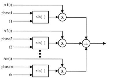
2.3.1.1 Fourier:
One of the most important and used tools in sound synthesis comes from the so called Fourier Transform (Oppenheim, Schafer et al. 1999). The Fourier transform states that any sequence (digital sound samples in our case) can be fully represented as a superposition of infinitesimally small complex sinusoids of different frequency, amplitude and phase. The synthesis formula for the Fourier transform is given by:
x[n] = 1f" X (e'
j)e'dW
(2)2)7 -"
where the X (e ") are complex coefficients that state magnitude and phase for the corresponding sinusoid of frequency (o. This synthesis formula can be represented by a topology graph as shown in Figure 4.
A 1(t) phasel sin( )X fl - -A2(t) phase2 sin() X f2 -0 An(t) phase n--- -sin( )X
Figure 4 Fourier Synthesis. Additive synthesis with fixed frequency sinusoidal oscillators.
The sound sources are sinusoidal oscillators with fixed frequency and phase. The amplitude of the oscillators is usually varied over time to simulate the varying characteristics of the spectra of real acoustic instruments.
The importance of Fourier synthesis/analysis is related with the fact that there are very efficient tools (mathematically and computationally) to realize direct and inverse Fourier transformations.
The types of functional elements present in Fourier synthesis are:
e Sinusoidal oscillators with variable amplitude and fixed phase and frequency * Addition
* Multiplication
2.3.1.2 Peak Tracking and Spectral Modeling Synthesis:
Unlike Fourier analysis where the goal is to represent a time signal with fixed frequency sinusoids, peak tracking finds a representation of a signal as the sum of sinusoids that vary their amplitude and frequency over time. The synthesis formula is very similar to Fourier synthesis, but the sinusoids are allowed to change their frequency over time. Usually, the number of sinusoids required to represent a given signal is significantly lower than in Fourier synthesis.
s(t)= I Ar(t)cos(,(t)) (3)
r=1
A variant of peak tracking called Spectral Modeling Synthesis (SMS) (Serra and Smith 1990), includes some components that are difficult to express as a sum of sinusoids. This approach represents a signal as a sum of sinusoids that vary their amplitude and frequency over time, plus a time-varying stochastic component (noise).
s(t) =
$A,(t)cos(O(t))+e(t)
(4)Automatic Generation of Sound Synthesis Techniques
These types of synthesis can be represented by the topology graph:
A1(t)
Figure 5 Peak tracking and SMS synthesis
The types of functional elements present in peak tracking and SMS techniques are: e Sinusoidal oscillators with variable amplitude, frequency, initial phase. " Addition
e Multiplication
e Stochastic signal (noise generator) (SMS) e Time varying filter (to shape the noise) (SMS)
2.3.1.3 Sampling, Multiple wavetable, wavestacking:
Sound sources have been so far represented as simple oscillators (sinusoids) with fixed or variable frequency, amplitude and phase. A source can be thought as a function that returns a value every time that is executed. This value is usually calculated in one of two ways: evaluating a mathematical function (i.e. sin(x)) or by reading from a table stored in memory (usually called wavetable)
-Sampling
The process of recording a sound into a waveform is termed Sampling. As a synthesis technique, sampling reproduces the waveform stored in memory using a source that reads a wavetable. This source can be implemented as a wavetable oscillator that reads the wavetable just one loop. An advantage of sampling is that it can reproduce "any" waveform, as long as it is stored in memory.
A(t)
index(t) --- pX output
-Wavestacking
This technique is built on the concept of sampling, but relies on the addition of multiple waveforms to form the final output. For our purpose it can be regarded as a similar method to Fourier synthesis, but having sources with waveforms of different types (not just sinusoids).
-Multiple wavetable
The idea here is to have "chunks" of sound that play in succession one after the other. To achieve this effect the amplitude of several sources is cross-faded to allow just one wavetable to be played at a given time. Ai(t) index1(t) a wavetable 1
A2(t)
index2(t) X + wavetable 2 Anex(t) index~t)M
wavetable nFigure 7 Multiple wavetable, wavestacking and ICA. Multiple Wavetable simply adds together different wavetables. Wavestacking incorporates more complex time envelopes. In ICA, each wavetable was extracted from an optimization procedure that separated a waveform in several "independent" components.
-Independent Component Analysis ICA:
Several mathematical analysis tools aim to decompose a sound in elements that can be added, multiplied or used to re-create the original sound (or a close approximation). From all these tools, ICA is one of the most commonly used (Casey 1998). Its most attractive feature is that it can decompose a sound in statistically "independent" components (this translates perceptually as elements "belonging together"). These components can be added together to form the reconstructed sound. It is possible to modify some aspects of some of the components in ways that preserve the structure of the original sound.
ICA synthesis is a straightforward additive synthesis, using the "objects" that were found in the analysis stage as sources in the wavestacking method. The analysis for ICA requires an iterative optimization process that can lead to diverse results.
Equation ( 5 ) shows a signal X formed by the additive sum of some independent components Zi
Automatic Generation of Sound Synthesis Techniques
X z+ y'i (5)
i=1 j=1
The main types of functional elements present in additive synthesis techniques are:
* Wavetable oscillators: Instead of a sinusoidal oscillator, these read from a wavetable with "any" waveform stored in memory.
" Addition " Multiplication.
2.3.2
Subtractive Methods:
The previous methods used addition of "simple" waveforms to form the desired sound. Subtractive synthesis uses the opposite principle: it creates a very complex sound, and removes unwanted elements from it. It makes heavy use of digital filters to shape the frequency content of a complex source signal (usually rich in frequencies). The frequency response of the filters is selected to match the spectrum of the desired sound, and the source is driven to generate a rich spectrum. The types of sound sources found in Subtractive Synthesis techniques have the special characteristic that produce complex waveforms rich in frequencies. Subtractive Synthesis usually follows the source + filter model. The filters that are proposed are linear, and quite simple in the case of the vocoder, and more complex (more poles/zeros) in the LPC case, but they can be decomposed into a system of simple filters in series or parallel (Oppenheim, Schafer et al. 1999).
2.3.2.1 Vocoders:
A bank of narrow band-pass filters (distributed along the frequency axis) is excited with a broadband signal (i.e. white noise, a square wave, a train of pulses, etc). The gain value in each filter is controlled and varied over time. With the right set of parameters this gives a very good approximation of the spectrum of the desired signal (Rabiner and Schafer 1978).
Figure 8 Simple vocoder. A source signal (rich in frequencies) is filtered by controlled bandpass filters.
2.3.2.2 Linear Predictive Coding (LPC)) synthesis
LPC implements a vocoder but replaces the narrow band-pass filter bank with a single and more complex filter that approximates the frequency response of some instrument (usually human voice, or an instrument with resonant cavities). The coefficients of this filter vary over time, and are updated to follow the changes in the spectrum of the original instrument. The types of sound sources employed to excite it vary from a pitched pulse train, to broadband noise (Rabiner and Schafer 1978) source 1 coefficients f -- pulse train Complex Filter source 2
noise
Figure 9 LPC synthesizer. Two types of sources can fed a complex filter, whose coefficients vary over time.
The main types of functional elements present in subtractive synthesis techniques are:
e Time varying sound sources: sometimes complex waveforms stored in a wavetable source.
* Filters: From simple narrowband filters with controlled gain, to more complex filters with coefficients that vary over time.
* Addition.
* Multiplication.
2.3.3 Modulation Methods:
Any property of a SST that can be varied over time is regarded as a modulation. In classic techniques, modulation has been used mainly to change amplitude, frequency or phase of a simple oscillator, with the objective of creating a rich and complex set of frequencies that vary over time. Most of the architecture of the modulation methods involves two (or more) controllable oscillators (usually with sinusoidal waveforms, but other simple waveforms are common: square, triangular, sawtooth).
2.3.3.1 Amplitude Modulation (AM) and Ring Modulation (RM):
As its name indicates, Amplitude Modulation modulates the amplitude of an oscillator with an unipolar time varying signal. Ring Modulation uses the same architecture, but the modulating signal used is bipolar.
Automatic Generation of Sound Synthesis Techniques
s(t) = A(t)sin(#)
with: A(t) 0 (unip
A(t) (bipc
(6) olar) Amplitude Modulation (AM)
olar) Ring Modulation (RM)
A(t)
control
Figure 10 Amplitude and Ring Modulations (AMIRM)
2.3.3.2 Frequency Modulation (FM):
The frequency of an oscillator varies as a function of time. This synthesis technique (and its variants) have been deeply explored. Summaries of these can be found in (Roads 1994; Boulanger 2000).
s(t) = A sin(C(t) + I sin(M (t))) (7)
M(t) sink) "' C(t)
Figure 11 Frequency Modulation (FM) synthesis. One of the most used synthesis methods FM has proved to be a very powerful (and computationally inexpensive) method for creating complex waveforms that offer very simple but meaningful controls.
2.3.3.3 Waveshaping:
This method uses a wavetable oscillator to control another wavetable oscillator. If both wavetables are sinusoids, this reduces to simple FM, but the more complex the wavetables, the more complex the produced sounds.
index,(t) - - -
-wavetable 1 index2(t) wavetable 1 output
Figure 12 Waveshaping: controlled wavetable oscillators in series. Generalization of modulation
techniques.
Waveshaping can include also a non-linear function instead of a wavetable module. The main types of functional elements found in Modulation Synthesis techniques are:
* Simple wavetable oscillators (with simple waveforms like sinusoidal, square, etc) in series or parallel.
* Controlled wavetable oscillators (allow control of the way the wavetable is accessed). * Non-linear function
* Addition e Multiplication
2.3.4 Physical Modeling:
Physical models are mathematical models that describe the behavior of physical systems. They are used to model the behavior of the air and some mechanical elements in acoustic systems. Because of the vast field of mathematical modeling, it is not feasible to encapsulate all the possible models under one category, but it is possible to outline some of the most common techniques and tools.
2.3.4.1 Waveguides:
Waveguides are based on the solution of the wave equation, that describes the behavior of a wave in a given medium. Their implementation usually involves a delay line that simulates the transmission and reflection of a wave in a given direction of a medium.
A very basic waveguide instrument, Karplus-Strong model (Boulanger 2000), is implemented using a delay line, filters and feedback.
... delay -- > filter F_
input routput
Figure 13 Generic Karplus-Strong string physical model.
2.3.4.2 Difference equations:
Physical systems are often described using differential equations, that ultimately describe the relationship between the inputs and outputs of a system. Symbolic solution of many of these equations is often very expensive computationally, not general enough, or simply not possible. Numerical methods based on difference equations give an accurate approximation of the behavior of these systems. Vibrating objects and their interaction are represented by a set of difference equations that are evaluated to produce sound samples. (Roads 1994). Difference equations are commonly used in fields like model analysis and signal processing. A common class of systems analyzed using difference equations are the Linear-Time Invariant systems where the input x(n) and the output y(n) satisfy a linear constant-coefficient difference equation of order N.
N M
(8)
1 ak y[n-k]= Eb 1x[n-m]
Automatic Generation of Sound Synthesis Techniques
Vast amounts of research in the analysis and use of these types of systems has been done (Oppenheim, Schafer et al. 1999). A first order system described by a simple difference equation is shown in equation ( 9 ) and Figure 14.
y[n] = 2y[n -1] + x[n] - 3x[n -1] (9)
-ydelay X -3
x[n] *+ 0 y[n]
2X delayH
Figure 14 First order difference equation depicted as a topology graph.
The most common functional elements found in physical modeling are:
* Delay by one sample (multiple samples delays are done using several one-sample delays).
" Addition * Multiplication
2.3.5 Summary offunctional elements
This is a list of the main types of functional elements found in our taxonomy: e Sinusoidal oscillators (variable amplitude, frequency, phase over time) * Wavetable oscillator (variable amplitude, read index)
* Delay (memory) for one or more samples * Controlled gain filter
"
Noise generator" Time varying filters (coefficients can change over time) " Addition
Automatic Generation of Sound Synthesis Techniques
3 DESIGN OF SOUND SYNTHESIS TECHNIQUES
3.1
DESIGN:
Lets us define the design of an algorithm as "the process that conceives the structural form and internal parameters of an algorithm, capable of producing a desired set of outputs, using a known set of inputs". For SSTs, which are algorithms for audio synthesis, the outputs are usually
in the form of digital sound samples (waveforms), and the inputs in the form of time varying control signals and static parameters.
3.1.1
Specifications of design for SSTs:
Different elements should be specified when designing a new SST. The final design has to follow strictly some of them but it can have more error tolerance than some others.
3.1.2
Inputs
The type and number of inputs essential. The number and type of inputs can be given as part of the design specifications (i.e. the SST is a sub-module from a bigger design). The inputs to a SST can be of many types, but they are usually classified in two main groups: static parameters
(updated at initialization time) and control signals (time varying signals that change their value during the evaluation of the algorithm).
One of the goals of SST design is to conceive algorithms where the inputs have "meaning" for the users. If a musician is using a SST that simulates the sound of a piano, it makes sense to have inputs that relate to the control of the "brightness" of the sound, the weight of the keys, or other piano-related variables that are present in the real world.
3.1.3 Outputs (TARGET)
For SSTs, the type of output is usually a sequence of digital audio samples (waveform), but other types of outputs could be easily specified if needed. The desired output is called TARGET, while the obtained output from any stage during the design is simply called output.
3.1.4
Error metric
All design processes need to measure the difference between desired and obtained results. In SST design the error is measured between the output and target waveforms in a given design. The error is usually measured using an error function, also called fitness function during this paper. This function computes some kind of "distance metric" between both waveforms and returns a value related to this distance. Because is a distance metric, it has the convention of being zero if both waveforms are identical, and a number greater than zero if they differ.
Human hearing is far from perfect, and it has been shown that very different waveforms (in a sample by sample sense) could sound "identical" or "similar" for a majority of listeners.
This redundancy can be exploited in the fitness function, and allow some "non perceived error" to be present in the output. In a future section we will discuss in detail some proposed fitness metrics. Therefore, the error metric (fitness function) should be completely described in the specifications of design. This is the "ruler" that will be used to decide if a design fulfills the requirements.
3.1.5 Implementation/algorithmic constraints:
Because SSTs are usually implemented in a digital computer that has limited resources, it is normal to include some implementation constraints in the specifications of design. Some of the constraints take the form of maximum allowed number of functional elements, size of the algorithm, execution time, real time capabilities, etc. Regardless of the platform where the SST will be implemented, all the designs have some boundaries and restrictions (i.e. an SST that requires infinite or too much memory is not realizable)
3.2
PROPOSED APPROACH FOR DESIGN OF SSTS
Design of an SST usually requires of two stages: first selection of a functional form for the SST, and then parameter estimation to find the right internal parameters for matching the performance of the SST to the desired target sound.
3.2.1 Classic design
In classic Sound Synthesis design a human realizes the first stage of the process. Functional forms are usually never conceived from scratch for a particular target sound. Instead, the designer selects one "template" from a set of known functional forms (i.e. the classic synthesis techniques) based on the characteristics of the target sound, and the known capabilities of the tentative functional forms.
In the second stage, the designer selects an approach for parameter estimation, and uses it to find the internal parameters that better "fit" the selected functional form to produce a sound "close" to the target sound. This part of the process has been automated with high success. (Homer, Beauchamp et al. 1993). The designer usually tries a handful of functional forms to select the one that results in a better match to the target sound.
In practice, it is common to find simple mixes of two or more synthesis techniques in a design. For example, to simulate the transient part of a sound is very complex with most of the synthesis techniques, but the steady state (sustained) part of the sound is fairly simple, so, a "hybrid" synthesis method could use sampling for the first part of the sound, and FM synthesis for the sustained. But is important to note that these kind of hybrid functional forms don't fuse in an intimate way, they just do a simple mix (usually additive) of their produced outputs.
Figure 15 Classic design of SST. Human selects a fixed Functional Form from a pre-defined set (i.e. "classic" SST) and uses a parameter estimation method. Human judges if the results are satisfactory
Automatic Generation of Sound Synthesis Techniques
A notable exception for this classic design process occurs in physical modeling, where a functional form is derived for each type of sound. The resulting functional form is usually related to the physical dimensions and properties of the system being emulated. But this physical model has to be as well handcrafted by a human designer.
3.2.2 Proposed approach for design
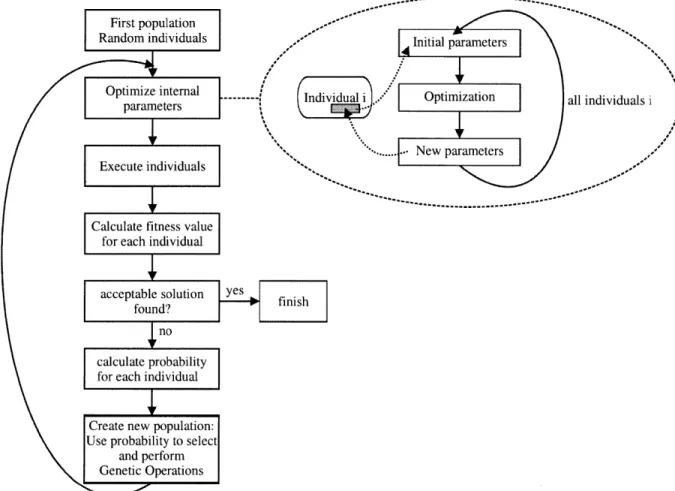
Our proposed approach tries to remove as much human intervention from the design process as possible. The first change (and maybe the most important) is to replace the first stage of selection of a pre-made functional form, by a "functional-form suggesting mechanism". This mechanism will suggest valid functional forms that can be tested to see if they are good or not for the desired goal. The second stage remains the same, and it consists in the parameter estimation for the "selected" functional form to try to match the target sound. Another point where the human intervention can be reduced is in the "error comparison" between the output sound and the target sound. This comparison (error function) will return a value that will be used for suggesting a new functional form, and that will try to minimize this error function. The procedure is repeated until the error falls within acceptable limits.
S ST suggestion aramete
func tion ed "funEtio
m
tion ----
use SST
couldimitial parameters functional "error" elemnents function C-3 target INPUTS OUTPUT
Figure 16 Suggested approach for design. Automated suggestion of Functional Forms, parameter estimation, and automated comparison of target/output sounds fed back in suggestion block.
It is important to note that the mentioned "functional-form suggestion mechanism" could operate in many forms, as long as the functional-forms that it suggests are valid. A simplistic approach could use a database of functional-forms, and just simply select one by one and wait for results. In this research, we decided to take a more adventurous path and elaborate a real "suggestion" mechanism that doesn't know precisely about the classic functional-forms, but it knows how to assemble many functional forms (classic and novel). This mechanism will be described later.
3.3
PARAMETER ESTIMATION
This stage has been extensively researched. We will give an overview of the techniques usually employed and their main goals. After this, we will introduce our approach for automation of the functional-form suggestion.
Once a functional-form has been selected (or suggested), the number and type of internal parameters remains fixed. A technique for parameter estimation can be used to find a set of values for those parameters that will reduce the error between the produced output and the target sound. This can be done using one of two approaches: mathematical analysis or optimization methods. The approach selected depends mainly in the type of functional form to be optimized and in the precision needed for its internal parameters. The fitness function (error metric) is used to guide the optimization process.
3.3.1 Mathematical analysis:
Many of the mathematical tools used to analyze signals can be used to extract meaningful information about our target waveforms, and in some cases that information can be used to infer the value of the internal parameters of a given SST. It is usual to find these tools in couples called transforms (Lindquist 1989). Transforms are couples of mathematical procedures that transform information (waveforms for us) from one domain into another. When they don't lose information in the process, it is possible to go from one domain into another and back without altering the original signal. When this is the case, the couple of procedures to go back and forth are called analysis/synthesis formulas.
3.3.1.1 Fourier:
Some functional-forms (SSTs) are intimately related to mathematical analysis/synthesis methods. The most notorious example is Fourier synthesis. The internal parameters for this SST are the same parameters returned by a Fourier analysis: magnitude and phase of the composing sinusoids. But Fourier analysis is a very valuable tool that can be used in conjunction with others to facilitate the parameter estimation process. A modification of Fourier analysis called Short Time Fourier tranform (spectrogram) (Rabiner and Schafer 1978) can be useful for analyzing frequency variations over time, onset/offset of components, and relative amplitudes of different components in frequency and time.
One example of the usefulness of Fourier analysis is when deciding the value of some filters to be used in subtractive methods, where a Fourier analysis can give an initial estimate of the desired frequency contour.
3.3.1.2 Cepstral Analysis:
Another popular analysis tool is called Cepsrtal Analysis. It gives an estimate of the broadband vs narrowband energy in the spectrum of a signal. (Rabiner and Schafer 1978) This analysis is useful to "isolate" the effects produced by a source, from the effects produced by a resonant system. It is often used in synthesis techniques that follow the source + filter model (i.e. LPC, Physical Modeling). Even though the results are just approximations of the real values, they are very good estimates.
3.3.2 Optimization methods:
Many interesting functional-forms of SSTs have no associated mathematical analysis tool that could be used to estimate their parameters. In these cases, optimization methods borrowed from systems, signals and control theory are useful. They are sometimes referred to as search methods, because they search for an optimal set of parameters in the parameter space associated with the SST. (Gershenfeld 1999).
Automatic Generation of Sound Synthesis Techniques
3.3.2.1 Parameter space:
Because the number of parameters is fixed (once the functional form of the SST has been selected), the space spanned by these parameters is fixed.
The size of this space (total number of different possible combinations) can be computed as follows. It is assumed that the SST will be implemented in a digital computer and the parameters will be represented by a fixed bit-size word. Then, the total number of possible different combinations C of parameters is given by:
C=2 BP (10)
with P number of parameters, and B the number of bits per parameter.
Using equation ( 10 ), for a SST with 10 parameters, and each parameter with 12 bits, a total of 21IX12 = 2120 1.3x 1036 combinations can be found in the space.
3.3.2.2 Fitness Function (error function):
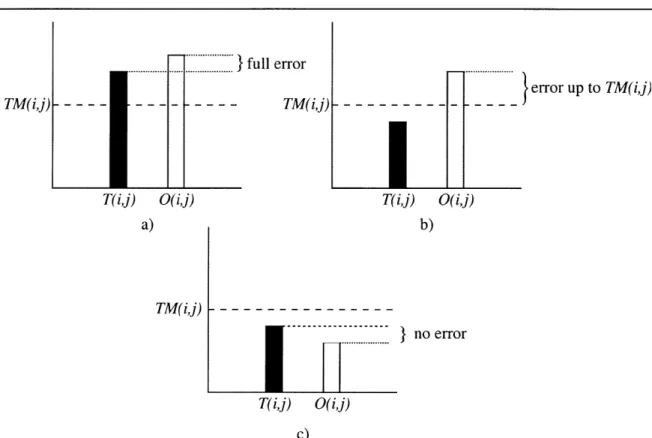
Each point in parameter space corresponds to a set of parameters that can be used with the selected SST to produce an output sound. This output can be fed into the fitness function specified for the optimization (error function) and compared to the desired target sound to compute an error value. This value is an indirect measure of the performance of the SST in that particular point of the parameter space. The task of the optimization method can be seen as "to find a point in parameter space where the related error value is minimal". If we map all the points of the parameter space into the related space of the error values, the resulting is called "fitness landscape" or "error landscape"(Press 1992; Gershenfeld 1999). It is possible to use the value of the error in the fitness landscape to decide where in the space are better points, and in that way guide the optimization process. But this is only possible if the fitness landscape is smooth. If the fitness landscape is rough, no inference can be done about the error value of the neighbors in any given point. This can be seen in the Figure 17 where three types of fitness landscapes (one-dimensional) are plotted.
a)
b)
c)
Figure 17 Fitness Landscapes. a) smooth, easy to be searched using an iterative method like gradient
descent. b) medium, more difficult for normal iterative methods. c) rough, iterative methods fail completely here. Parallel methods are necessary