HAL Id: hal-00993656
https://hal.archives-ouvertes.fr/hal-00993656
Submitted on 19 May 2017
HAL is a multi-disciplinary open access
archive for the deposit and dissemination of
sci-entific research documents, whether they are
pub-lished or not. The documents may come from
teaching and research institutions in France or
abroad, or from public or private research centers.
L’archive ouverte pluridisciplinaire HAL, est
destinée au dépôt et à la diffusion de documents
scientifiques de niveau recherche, publiés ou non,
émanant des établissements d’enseignement et de
recherche français ou étrangers, des laboratoires
publics ou privés.
Dew architectures - Dew annouces the good weather
Daniel Beysens, Filippo Broggini, Iryna Milimouk-Melnytchouk, Jalil
Ouazzani, Nicolas Tixier
To cite this version:
Daniel Beysens, Filippo Broggini, Iryna Milimouk-Melnytchouk, Jalil Ouazzani, Nicolas Tixier. Dew
architectures - Dew annouces the good weather. Matérialités contemporaines = Materiality in its
contemporary forms : architecture, perception, fabrication, conception. MC 2012 Symposium,
Ville-fontaine, novembre 2012, 2012, Isle d Abeau, France. pp.282-290. �hal-00993656�
Dew architectures
“Dew announces the good weather”
Beysens Daniel1, Broggini Filippo2,
Milimouk-Melnytchouk Iryna & Ouazzani Jalil3 Tixier Nicolas4 1ESPCI-PMMH, CEA-Grenoble et OPUR - France
2Agence BlueOfficeArchitecture - Bellinzona - Suisse 3ARCOFLUID - France
4 ENSA Grenoble & ESAA Annecy
Laboratoire CRESSON - UMR CNRS n°1563
Abstract
Dew is a natural phenomenon that occurs under particular weather
conditions (clear nocturnal sky, humid air, low wind) and on a surface
specially designed for this purpose (high radiative cooling properties,
special architectural design). Depending on the weather conditions and
the surface characteristics, the water yield can give up to 0.7 litres per
square meter and per night.
Although the collection of rain water on roof turns out to be relatively
simple, dew harvesting needs a more sophisticated architectural design
to be efficient. Then this project aims at testing roof designs that improve
dew water recovery by modulating two major parameters related to its
recovery: (i) surface quality (strong emissivity, wetting character, low heat
capacity), (ii) the shape of the roof (slopes, orientations with respect to
dominant wind, gravity-induced water flow, etc.).
A first step was the exploration of urban structures/sculptures, which
was carried out by numerical works and small scale modelling (workshop
held on December, 2008). In a second time (April, 2008), three roof
prototypes on scale 1:1 of approximately 4 m
2each are constructed and
tested. These prototypes are designed with metals (sets of oriented plane
surfaces), resins (modular plays of crooked surfaces) and textile (stretched
structures).
These multi-disciplinary researches on dew water harvesting aims at a
synergy between partners of different disciplines and statutes: physicists,
architect-designers, industrialists and teachers. They can apply to all the
scales of the habitat, from garden cabins to roofs of building, car parks or
supermarkets. It finds its interest in many regions of the world, in arid or
semi arid environment and also European countries. (It is worth noting
that the surface coating used to improve dew collection also provides
natural cooling during the day.). We propose on conclusion of this paper,
a pavilion project with on of this system.
Introduction
Passive dew collection refers to the condensation of atmosphere vapour by radiative exchange cooling and without external energy. It is known to provide good quality water and can provide a useful supplementary source of drinking water. Although the maximum expected available yield is in the order of 0.8 Lm-2night-1, such an amount has yet to be
reported. The highest dew collection amount we are aware of is just over 0.6 Lm-2night-1
for Jerusalem (S. Berkowicz, Hebrew University, personal communication July 2012). In contrast to meteorological conditions, which cannot be modified, the shape of the condenser can increase or lower the dew yield by a large factor. In order to increase the dew yield, we here propose and test new collector shapes different than the planar geometry used to date.
Simulation
Dew formation involves radiative cooling below the atmosphere dew point temperature. What matters is the difference between the condenser outgoing radiative power, Pr, and the sky incoming radiative power, Ps. The local radiative power, P, emitted by a source depends on the local temperature, T, through the Stephan-Boltzmann law,
P = εσ (T + 273)4 , (1)
where σ is the Stephan-Boltzmann constant and ε is the emissivity of the surface.
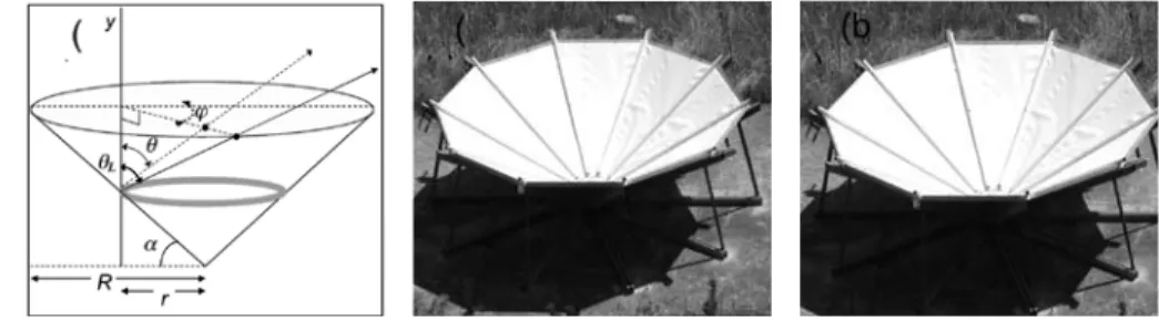
When considering a complicated surface, such as the cone in fig. 1, the radiative power emitted by each surface element over a given sky solid angle element must be integrated over the total condenser structure and visible sky solid angle. This necessitates considering both the surface directional emissivity (that varies as the cosine of the angle with the normal to the surface element) and the sky directional emissivity εs,θ. Due to this
specific θ dependence, the lowest atmospheric layer contained in the first 15° solid angle emits a significant amount (25 %) of the total IR sky radiation. In [1] numerical simulations of substrates - horizontal, 30° inclined planar substrate, conical and ridge shapes - were performed and compared to experiments outdoors.
Numerical calculations were made for a condenser taken as a “grey” body with emissivity
εc = 0.94 and a sky radiation corresponding to common night weather conditions in a
temperate climate (e.g. Europe): clear sky, Ta = 288 K (15°C) ambient temperature and
RH = 85% relative humidity, corresponding to the dew point temperature Td = 285.5
K (12.5 °C). The integrations of the radiative budget are computed for various radiator temperatures Tc . Among the collection surface forms already investigated (planes, ridge,
cone [1]), the latter conical or funnel shapes gave the best results. Fig. 2 compares surface mean temperature with respect to wind speed for a conical geometry and a 1 m2
condenser inclined 30° from horizontal, with wind blowing towards the hollow part of the condenser. As expected, cooling decreases when wind speed increases.
Shapes
A good condenser design will reduce the heat exchange of the condenser surface with air flow (free convection, forced convection with wind). Hollow forms, such as the funnel shape, are preferred as they also reduce free convection along the surface by blocking the heavier cold air at the bottom. In addition, because of the cone symmetry with respect to the vertical axis, the effects are the same whatever the wind direction. Assuming a symmetric temperature distribution with respect to the vertical axis over the internal funnel surface, a portion of the surface is in radiative equilibrium with the remaining parts of the surface, such that the internal radiative budget is null. In addition, in masking the lower
(and most IR emissive) atmospheric layer to most of the surface, the funnel shape lowers the intensity of downward long wave sky radiation and thus enhances the radiative cooling power. Cooling is thus expected to increase and condensation enhanced with respect to the inclined planar condenser.
When dealing with a cone, choosing a smaller cone angle (larger α) reduces convection
heating but also reduces radiative cooling because the radiation solid angle of the sky is lower. The optimal cone angle was deduced from several simulations with different wind speeds and for different cone angles while keeping the cone radius constant at 1.5 m (i.e. the condenser area projected on the ground). The mean condenser surface temperature <Tc> was obtained by averaging the local surface temperature over the
condenser area. From simulations at angles a = 25°, 30°, 35°, 40° and 50°, the a ≈ 30° angle (cone angle ≈ 60°) give the best cooling efficiency.
Choice of design
Hollow shapes are preferred, as discussed above, with a particular interest for slopes around 30°. This hollow configuration (i) prevents the lower layers of the atmosphere to radiate inside the cone and thus improve cooling, (ii) lowers the influence of wind forced convection, whatever the wind direction, and (iii) confines cold air inside the cone by buoyancy. Incidentally, this angle is also the optimal angle for plane condensers [2]. In addition, this particular angle allows water to easily flow by gravity as the gravity forces are only reduced by 50 % with respect to vertical.
Such conical shapes have already been tested [1,3], or similar shapes such as a square hollow pyramid with angle 30° from horizontal [4]. The yields are compared to the 1 m2
Figure 1 Integration scheme for the funnel shape ( 0 < θ < θL , 0 < φ < 360° and 0 < r < R). (b) Photo of the funnel-shaped condenser (7.3 m² surface area with 60° cone angle, 30° from horizontal). The internal surface of the experimental condenser is coated with OPUR (www.opur.fr) low density polyethylene film insulated from below with 3 cm styrofoam.
Figure 2 Averaged condenser surface temperatures <Tc> as obtained by numerical simulation with respect to wind speed at 10 m elevation. No condensation occurs above the broken line <Tc> > Td = 285.5 K (12.5 °C), corresponding to Ta = 288 K (15°C) and RH = 85 %. 1
planar reference condenser inclined 30° from horizontal through the ratio R:
where hc,0 is the volume of dew water collected per day and per unit projected area
of condenser surface. The subscripts (c) and (0) stands for the collector and planar
reference, respectively. When compared with a reference planar condenser inclined 30° from horizontal, the yield is increased. In [1] the improvement is 22 % on average, ranging from 30% at windspeeds below 1.5 m/s to 0 % above 3 m/s (fig. 3). The gain is larger for low dew yields, see Fig. 4a. The inverted pyramid with angles 30° from horizontal gives on average a 20 % higher yield [4], with also a tendency to higher yields for low dew volumes (fig. 4b).
In this study, a pyramidal shape condenser (fig. 5) was assembled but it was not tested in the field because of the above studies. The interest of our design was the use of an industrial flexible texture. The thermal insulation was made according to the principle of a double-skin filled with rockwool.
Figure 3 Dew gain R of a 7.3 m2 cone with respect to a 1 m2 plane as measured in Ajaccio, France, from May 25, 2005 to November 11,
2005 (107 dew events, see [1]; black curve: 100 % weighted fit of data).
Figure 4 (a) Comparison of the mean daily collected dew amounts between the 1 m2 planar and 7.3 m2 conical collectors, from May 25,
2005 to Nov., 11 2005 in Ajaccio, France (semi-log plot; the line is an ad-hoc power law fit with exponent -0.3; adapted from Ref. [1]). (b) Comparison of the mean daily collected dew amounts between the 1 m2 planar and pyramid collectors, March 2004 to May 2005 in
Wageningen (The Netherlands). (Semi-log plot; the line is an ad-hoc power law fit with exponent -0.23; adapted from Ref. [4]. 3
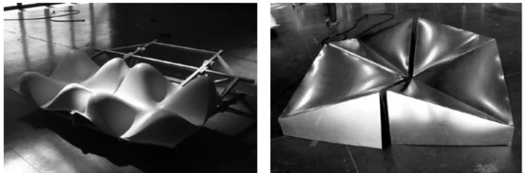
When considering the construction of large scale collectors, the conical shape is technically difficult to envisage and is costly. In its place, we considered hollow shapes that can be made repetitive to eventually pave a planar or weakly curved surface (roof). We also looked for the aesthetics of the ensemble and the cost of construction. From the many shapes that were studied, we retained only two: the egg-box (EB) and origami (OR) types (fig. 6). Two roofing units were erected, 4 m² projected on the ground (EB) and 3.24 m2 (OR). For improved performance, the external surface was coated with a paint
containing an additive that makes it hydrophilic and gives it a high infra-red emissivity. Each condenser was coated below with styrofoam thermal isolation. The prototypes were fabricated in 2008 at « Les Grands Ateliers » (Villefontaine - France) during the “Chaleurs urbaines” project (ENSA de Grenoble - Métro).
Study site
The study site is located south of the Bordeaux urban area, in the town of Pessac at Le Bourghail (44° 48’16’’ N, 0°41’34’’ W), approximately 17 m a.s.l. The dominant wind direction during the night (21:00 - 06:00) is SW (240°). The distance from the Atlantic Ocean is about 50 km. The dew condenser has been described in [2]. It consists of a plane foil covering a 1 m x 1 m surface area, thermally isolated from below with a 20 mm thick sheet of polystyrene foam. The foil composition is from [5,6], is 0.39 mm thick and made of 5.0 vol % of TiO2 microspheres of 0.19 µm diameter, and 2.0 vol % of BaSO4 of 0.8 µm
Figure 6 (a) Egg-box shape (2 m x 2 m). (b) Origami shape (1.8 m x 1.8 m).
Figure 5 Inverted pyramid with an angle 30° from horizontal and four condensation side. The section at the top is 1 m x 1 m. 5
diameter embedded in a matrix of low-density polyethylene (LDPE). It also contains approximately 1 vol % of a surfactant additive non-soluble in water. This material improves the mid-infrared emitting properties to provide radiative cooling at room temperature and efficiently reflects the visible (sun) light.
The planar condenser was set at an angle of 30° with respect to horizontal. A PVC gutter collects water into a polyethylene bottle. No scraping was performed and dew water was collected only by natural gravity flow.
The collectors are set above the ground and faced west. The EB collector was slightly inclined (about 10°) to collect water. For the OR structure, water was collected by a hole made in its centre.
An automatic meteorological station (Oregon Scientific, USA) continuously recorded the following parameters: air relative humidity, air and dew point temperature, wind direction, and windspeed.
Measurements
The data were collected during 51 days, between 29/08/2009 to 18/10/2009; 23 dew events occurred (45 % of the period) and 2 days of fog (4% of the period). The yields were compared to the 1 m2 planar reference condenser through the ratio R (see Eq. 2).
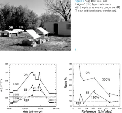
The evolution of dew yields hc,0 for the different structures are reported in fig. 8a.
The mean values (in Lm-2day-1) are <h> = 0.054 for the planar reference, 0.059 for the
EB and 0.12 for the OR, corresponding to R mean values <R> = 1.09 and 2.22 for the EB
and OR, respectively. This ratio should be dependent on wind speed (see above fig. 2,
Figure 7 “Egg Box” (EB) and “Origami” (OR) type condensers with the planar reference condenser (R). (T is an additional planar condenser).
Figure 8 (a) Evolution of dew yields (Lm-2day-1) for the origami (OR, squares, full line), egg box (EB, short dashed line) and reference
plane (REF, triangles, long dashed line) with mean values - horizontal lines). (b) Ratio R of the condenser to the reference plane with respect to dew yields (OR, squares, full line), (EB, dashed line). The thick lines are 100 % weighting of the data.
7
where a weak dependence is seen). However, other factors are important such as the efficiency of collection, which depends on the collected volume. This is why we report in fig. 8b the variation of R with respect to h0, the planar reference yield. There is a general
tendency to increase dew yields for small yields, with a ratio that can reach about 400 % for the OS and 150 % for the EB.
Discussion
It is clear that the OR structure is more effective than the planar reference and than the EB structure, especially for light dew episodes. The lower performance of the EB type when compared to the OR structure is due to the flat top of the EB structure from where dew cannot flow easily, thus reducing the efficiency. In addition, one should note that for our test of the modules, construction irregularities can have a considerable effect on the flow. Without reaching the output of the origamic structure, a better output of the egg-box is possible without joints. The EB structure, however, always remains more effective than a simple plane.
This study shows that the geometry of collectors can have a considerable influence on dew yield. Hollow structures increase cooling by preventing wind influence and are preferred over planar surfaces. However, the efficiency of water collection also matters. When the angle with vertical becomes too low, as on the top of the egg-box bumps, water cannot flow and the yield is reduced.
There is also a positive effect of the edges (fig. 9) for water collection. The dew drops on the edges are forced to coalesce on a line instead of a plane. This enhanced coalescence process speeds up droplet growth such as they detach sooner than the other drops on the substrate. When flowing down, the edge droplets coalesce with other drops, grow in an avalanche-like process and form rivulets. Flowing down is later enhanced where rivulets have formed, which increases the collection of further condensed dew water.
This accelerating mechanism is absent from collectors without sharp edges, like the EB.
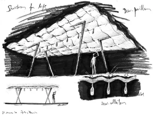
Concluding remarks
One of the difficulties of the plane surface to be used for dew collection is its employ as a roof. Classically, with houses having two sides roofing, water flow is difficult in the channels/gutters because their slope is generally not strong enough. One of the principles that has controlled the present research for new forms is then to propose a flexible system increasing the surface of collection (physical dimension), creating structures to be used as shelters (social dimension) while solving by different channels/gutters the problem of the flow for dew water recovery (constructive dimension).
Many forms can then be designed and tested for dew collection. However, they should
Figure 9 Edge effects on dew water collection. Drops are larger on the edge where they induce avalanches (rivulets) when sliding down. (Hydrophilic paint on a cooled vertical stainless steel foil. From Ref. [7]).
follow general rules in order to obtain good yields. Our goal in the suggested forms presented here is to increase the surface of collection without increasing the height of the module much. This characteristic associated with repetition and the assembly of the modules suggests that modular structure for dew collection can be used that can also serve as a roof to be used on homes, public use, industry, and other built structures.
Opening: a pavilion project
Since 2010, as a continuation of the initial experiments, the pavilion project is under development. The goal is to design and build a roof device that combines the principles of dew formation and that of a static self-supporting system.
By combining two double-curved surfaces - one on top and one at the bottom - with an «intermediate mass», we get a statically very interesting sandwich.
Both surfaces are materialized by the lamination of a carbon glass fibber fabric
impregnated with matrix polyester. These two layers are connected by polyurethane foam, which guarantees the transfer of the static efforts and gives the necessary resistance to the sharp effects.
The current research aims at optimizing three parameters of the form:
- The geometry of the top layer, following the principles of dew formation: optimizing the average slope, minimizing the routes of water harvest...
- The geometry of the bottom layer guarantees an optimal static behavior: inertia, efforts on the junction areas...
- The thickness (variable) of the «intermediate mass», which is not only proportional to the inertia, but also ensures an adequate thermal insulation by increasing the temperature difference between the upper and lower layers of the device.
By the idealization of a system of assembly among the various units (cables of compression, joints of assembly…) one can provide a roof that can be easily assembled and very light. It can be modulated in its plan dimensions and can thus be placed on pillars, gates, etc. The aerodynamic behavior of the device has also been studied. The elements of the edge should be able to deflect the airflow so as to minimize the effects of depression on the
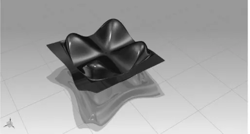
Figure 10 Three-dimensional modelling of the upper shell of the base module with edge and angle.
roof. The positioning of a possible system of facade should also be taken account from the aerodynamic point of view.
The construction of a pavilion prototype will allow us to clearly define all the phases of production, construction, transport and assembly, just as its prices of production. At the same time, the real effectiveness of the device in arid medium will be checked. Once these data are collected, the commercial phase for the distribution of the “product-house” could start on a broader scale.
Acknowledgments
We gratefully thank Yi Duan, A. Kitromilides, A. Roche, K. Spanou and A. Ulisse for the prototype constructions (more documents at www.grenoble.archi.fr/chaleursurbaines). We are very grateful to S. Berkowicz, Hebrew University of Jerusalem, for his critical reading, helpful remarks and relevant suggestions.
Figure 11 Preliminary sketch of the assemblage of the device
Figure 12 Perspective views of the pavilion: the roof and the pillars / roof in bird’s eye view 11
References
- Awanou C.N., Hazoume R.P. (1997), Study of natural condensation of atmospheric humidity, in Renewable Energy, 10, pp. 19-34
- Beysens D., Milimouk I., Nikolayev V., Muselli M., Marcillat J. (2003), Using radiative cooling to condense atmospheric vapor: a study to improve water yield, in Journal of Hydrology, 276, pp. 1-11
- Bibi H., Medici M.G.M., Mongruel A., Beysens D. (2012), Collection of dew water droplets: the effect of substrate edges, PMMH Internal report
- Clus O., Ouazzani J., Muselli M., Nikolayev N., Sharan G., Beysens D. (2009), Comparison of various radiation-cooled dew condensers using computational fluid dynamics, in Desalination, 249, pp. 707-712
- Jacobs A.F.G., Heusinkveld B.G., Berkowicz S.M. (2008), Passive dew collection in a grassland area, The Netherlands, in Atmospheric Research, 87, pp. 377-385
- Nilsson T.M.J., Vargas W.E., Niklasson G.A., Grangvist C.G. (1994), Condensation of water by radiative cooling, in Renewable Energy, 5, pp. 310-317
- Nilsson T.M.J. (1996), Initial experiments on dew collection in Sweden and Tanzania, in Solar Energy Materials and Solar Cells, 40, pp.23-32
![Figure 3 Dew gain R of a 7.3 m 2 cone with respect to a 1 m 2 plane as measured in Ajaccio, France, from May 25, 2005 to November 11, 2005 (107 dew events, see [1]; black curve: 100 % weighted fit of data)](https://thumb-eu.123doks.com/thumbv2/123doknet/12973711.377843/5.680.45.299.42.267/figure-respect-measured-ajaccio-france-november-events-weighted.webp)