HAL Id: cea-02368504
https://hal-cea.archives-ouvertes.fr/cea-02368504
Submitted on 18 Nov 2019
HAL is a multi-disciplinary open access
archive for the deposit and dissemination of
sci-entific research documents, whether they are
pub-lished or not. The documents may come from
teaching and research institutions in France or
abroad, or from public or private research centers.
L’archive ouverte pluridisciplinaire HAL, est
destinée au dépôt et à la diffusion de documents
scientifiques de niveau recherche, publiés ou non,
émanant des établissements d’enseignement et de
recherche français ou étrangers, des laboratoires
publics ou privés.
Vertically aligned carbon nanotubes black coatings from
roll-to- roll deposition process
Thomas Goislard de Monsabert, L. Papciak, A. Sangar, J. Descarpentries, T.
Vignal, Xavier de Longiviere, D. Porterat, Q. Mestre, H. Hauf
To cite this version:
Thomas Goislard de Monsabert, L. Papciak, A. Sangar, J. Descarpentries, T. Vignal, et al.. Vertically
aligned carbon nanotubes black coatings from roll-to- roll deposition process. International Conference
on Space Optics 2016, Oct 2016, Biarritz, France. pp.1056250 - 1056261, �10.1117/12.2296243�.
�cea-02368504�
31. ente Biarritz, France on Space Optics 18-21 October www.icso2016.com
International Conference on Space Optics
Biarritz, France
18–21 October 2016
Edited by Bruno Cugny, Nikos Karafolas and Zoran Sodnik
Vertically aligned carbon nanotubes black coatings from
roll-to-roll deposition process
Thomas Goislard de Monsabert
L. Papciak
A. Sangar
J. Descarpentries
et al.
International Conference on Space Optics — ICSO 2016, edited by Bruno Cugny, Nikos Karafolas, Zoran Sodnik, Proc. of SPIE Vol. 10562, 1056250 · © 2016 ESA and CNES
e.y¡i"4y
ICSO 2016 Biarritz, France
International Conference on Space Optics 18 - 21 October 2016
VERTICALLY ALIGNED CARBON NANOTUBES BLACK COATINGS FROM
ROLL-TO-ROLL DEPOSITION PROCESS
T. GOISLARD de MONSABERT(1), L. PAPCIAK(1), A. SANGAR(1), J. DESCARPENTRIES(1), T.
VIGNAL(1,3), X. de LOGIVIERE(1), D. PORTERAT(2), Q. MESTRE(2), H. HAUF(1)
(1) NawaTechnologies, 190 Av. Célestin Coq, 13106 Rousset Cedex, France
(2) NIMBE, CEA, CNRS, Université Paris-Saclay, CEA Saclay 91191 Gif-sur-Yvette, France
(3) Laboratoire de Physicochimie des Polymères et des Interfaces (EA 2528), Université de Cergy-Pontoise,
5 mail Gay Lussac, Site de Neuville, 95031 Neuville-sur-Oise, France
I. INTRODUCTION
Vertically aligned carbon nanotubes (VACNTs) have recently attracted growing interest as a very efficient light absorbing material over a broad spectral range making them a superior coating in space optics applications such as radiometry, optical calibration, and stray light elimination. However, VACNT coatings available to-date most often result from batch-to-batch deposition processes thus potentially limiting the manufacturing repeatability, substrate size and cost efficiency of this material.
Here we report on the synthesis of VACNT coatings through a scalable and cost-effective one step process and on the on-going development of a continuous roll-to-roll deposition process of VACNTs on 300mm wide metal foil. We also present the optical absorption properties of this black coating after deposition and after post-processing steps including physical transfer onto destination substrate and plasma etching. Finally, we discuss preliminary data on the compliance of this cost-effective large-area black coating with space application requirements such as low outgassing properties.
II. INDUSTRIAL MANUFACTURING
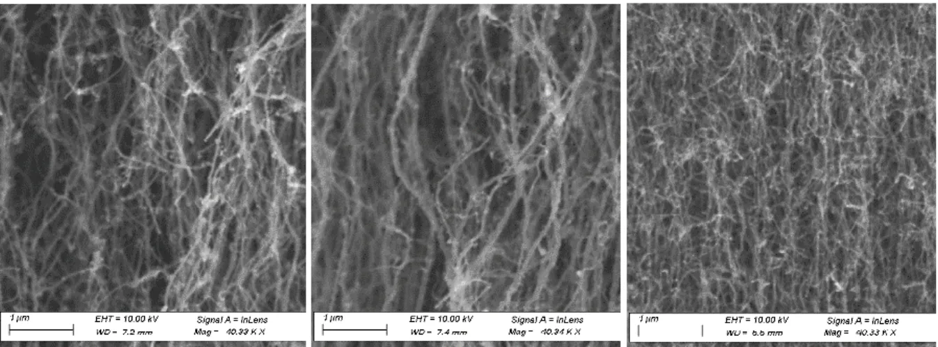
Vertically aligned carbon nanotubes are tubular nanostructures made of graphitic carbon (carbon nanotubes) grown on a substrate with their axis perpendicular to the substrate. These nanotubes usually exhibit diameters in the range 10-100nm and lengths in the range 50-1000µm. Aerosol-assisted Catalytic Chemical Vapor Deposition (CCVD) process is a one-step CVD process which enables to synthesise VACNT at atmospheric pressure on different substrates such as quartz, silicon, steel [1, 2], and more recently aluminium by decreasing significantly the synthesis temperature at c.a. 600 °C. The specificity of this process is the simultaneous feeding of the reactor with both the carbon source and the catalyst precursor which enable to continuously grow VACNT. Based on this process, a first batch-to-batch equipment has been realised at CEA in 2011 able to grow VACNT on 12 inches Si-wafers and a half-scale industrial roll-to-roll, atmospheric pressure CVD reactor is now operated at NAWATechnologies able to continuously produce VACNTs on 300mm wide metal foil. The aerosol assisted CCVD process is currently being implemented in this tool at our pilot line facility in Rousset, France (see Fig. 1).
Fig. 1. Left: the roll-to-roll reactor; Center and right: SEM views of VACNTs grown in this reactor by
o;rm EL17 =10.00kV S1prelA=inLens WG- l.? mm A4a0 = 40.33XX
lum fHt= 10 00 kV SrgrslA = inters WD- 6.6mm nPag= 40.33NX
III. OPTICAL PROPERTIES
The optical reflexion properties of VACNTs synthesized by atmospheric pressure, aerosol assisted CCVD either on Si wafer or on Aluminium foil have been characterized with a UV/Vis/NIR spectrophotometer (Perkin Elmer Lambda 950) in the spectral range 320-2000nm. These samples have been produced at laboratory scale by CEA in the framework of a join laboratory between NawaTechnologies, CEA and University of Cergy Pontoise. The specular reflectance spectrum has been measured for all samples at incident angles of 8° and 30° with identical results. Total hemispherical reflectance has been measured for some samples (with 8° incident angle).
A. Effect of thickness and diameter
Various process conditions have been applied to synthesize VACNT samples with different morphologies on Si wafer. Besides, aluminium foil being a substrate of choice for roll-to-roll synthesis of VACNTs, and the nature of the substrate being a strong influencing parameter in catalytic CVD processes, we have also included one sample of VACNTs grown on Al foil in this comparative study.
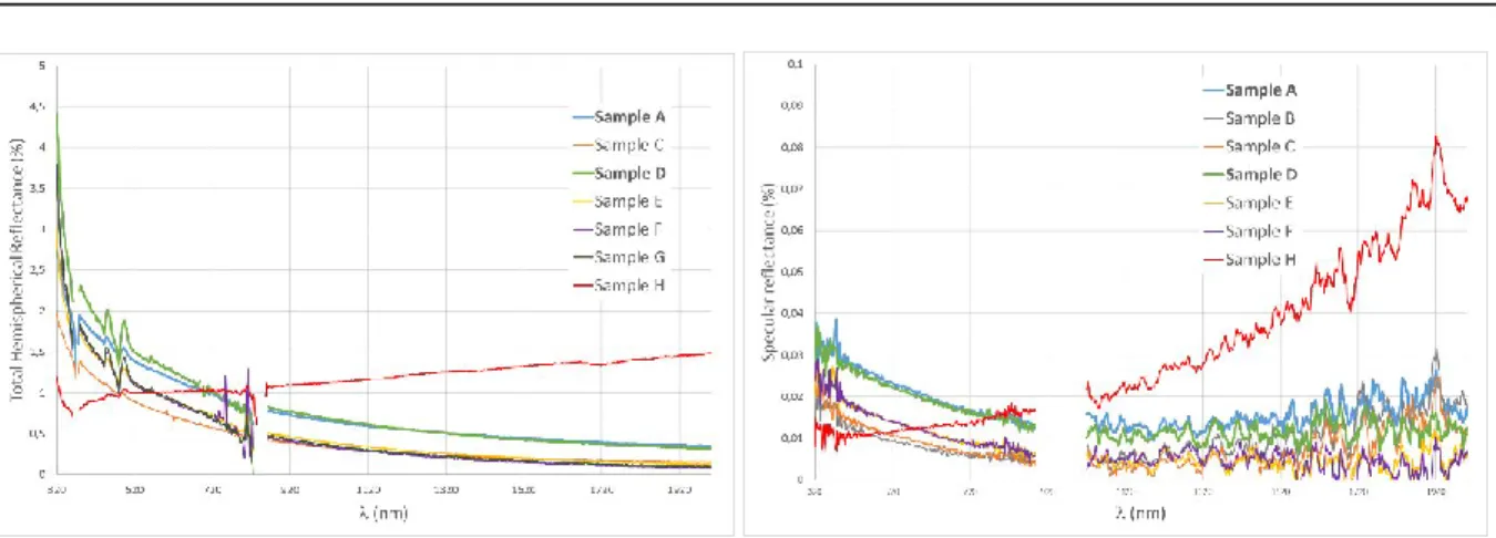
From SEM observation, the main differences between these samples are the thickness of the film (i.e. the length of the VACNTs) and the apparent diameter of the VACNTs. It is worth nothing that apparent diameters measured from SEM images may not coincide to individual carbon nanotube diameters as carbon nanotubes may exhibit a carbonaceous surface layer and/or they can assemble together to form bundles. The morphological and optical reflexion properties of these samples are summarized in Table 1. Some typical SEM cross-sections are shown in Fig. 2 and the reflectance spectra are plotted in Fig. 3.
Sample Substrate Thickness Apparent
diameter Total R @ 600 nm Specular R @ 600 nm Total R @ 1600 nm Specular R @ 1600 nm A Si 206 µm 35-110 nm 1,213 % 0,020 % 0,421 % 0,018 % B Si 438 µm 30-40 nm 0,008 % 0,011 % C Si 478 µm 30-40 nm 0,768 % 0,009 % 0,187 % 0,010 % D Si 485 µm 60-80 nm 1,285 % 0,020 % 0,402 % 0,014 % E Si 585 µm 30-40 nm 0,936 % 0,012 % 0,183 % 0,005 % F Si 693 µm 30-40 nm 0,920 % 0,012 % 0,136 % 0,007 % G Si 703 µm 30-40 nm 0,957 % 0,012 % 0,159 % H Al 130 µm 30-40 nm 1,009 0,013 % 1,358 % 0,046 %
Table 1. Morphological and optical reflexion properties of VACNTs grown by atmospheric pressure, aerosol
assisted CCVD process on Si substrate under various process conditions.
II---
INI----1,LS
-Sample A -Sample C -Sample D -Sample E - -Sample F -Sample G -Sample H X, lent) -SampleA -Sample 8 -Sample C -SampleD -Sample E -Sample F -Sample H 1 1 11 i{yl
V\d4 4 Vi /MV"I'
,,,,.lN,l,:A
4f (nm)ICSO 2016 Biarritz, France
International Conference on Space Optics 18 - 21 October 2016
Fig. 3. Optical reflection spectra. The missing data have been intentionally removed due to low S/N ratio.
These results suggest that, at least for this set of samples, the main morphological parameter driving the optical reflectance in the visible and near infrared spectral range is the apparent diameter of the nanotubes. Indeed, the samples exhibiting a distribution of apparent diameters ranging between 30 and 40nm are less reflective than other samples containing larger apparent diameter carbon nanotubes. The thickness of the VACNT film doesn’t play a crucial role in the reflectance level. One sample however does not follow this trend: sample H with VACNTs grown on Al substrate. This points towards another influencing parameter for the reflectance of VACNTs, possibly the density of carbon nanotubes. Work is in progress to clarify this point.
In agreement with literature data on the reflectance of VACNTs [3, 4, 5], the total hemispherical reflectance is below 2% and the specular reflectance is below 0,02% for most samples at wavelength above 400nm. This confirms the diffusive behaviour of VACNTs as a very low reflectance coating.
B. Top vs Bottom: transfer onto destination substrate
The thermal CVD synthesis of VACNTs can only be applied to substrates withstanding temperature above 450°C. This can be a serious restriction for coating optical or structural parts without deterioration. One possibility to solve this issue is to transfer the VACNT film from its original substrate onto a destination substrate of interest (the part to be coated). When the original substrate exhibits some flexibility (as metal foils do), this technique can be applied to destination substrates with curvature or complex shape.
Sample Substrate Thickness Apparent
diameter Total R @ 600 nm Specular R @ 600 nm Total R @ 1600 nm Specular R @ 1600 nm A Si 206 µm 35-110 nm 1,213 % 0,020 % 0,421 % 0,018 % A Bottom Plastic 206 µm 35-120 nm 0,775 % 0,009 % 0,276 % 0,020 %
Table 2. Morphological and optical reflexion properties of VACNTs before (A) and after (A Bottom) transfer
i
.1 pro EHi=10.00kV 51gnBJA=lOLev.
WD- 9.7071I1 Mg. 30.2Y1() S1gnBJA = InLe, Whig= 30231C -Sample A - -Sample A Bottom 2,5 X C 2 u ac v1,5 Ñ 4 r v - il " x I l 320 520 720 920 1120 1320 1520 1720 1920 i(nm) (nm)
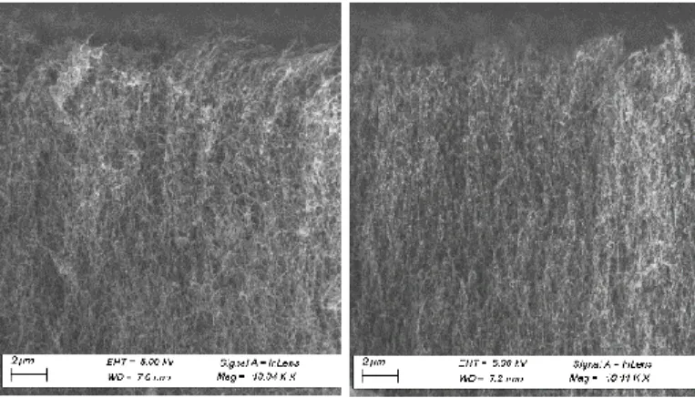
Fig. 4. SEM X-sections (left) and top views (right) of VACNTs before (A) and after (A Bottom) transfer on a
plastic substrate.
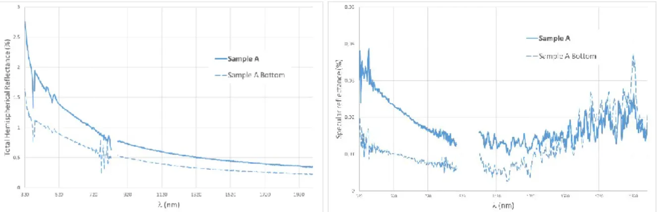
Fig. 5. Optical reflection spectra of VACNTs before (A) and after (A Bottom) transfer on a plastic substrate.
To assess the optical reflexion properties of VACNTs after transfer onto a destination substrate we applied a thin layer of epoxy glue on the top surface of a VACNT film, then we placed a plastic plate on top and, after drying the glue in ambient air for 24 hours, the plate was removed. The VACNT film was stuck on the plastic plate with its original bottom face now facing up.
Optical and SEM characterizations have been performed on this sample and compared to the same VACNT film before transfer. The results are presented in Table 2, Fig. 4 and Fig. 5. They show a decrease in the reflexion properties (both specular and total) associated with a slight increase in the carbon nanotube apparent diameter and a better alignment of the carbon nanotubes. This suggest that alignment plays a significant role in the reflectance of VACNT films thus providing a path for improvement. It also demonstrates that transferred VACNTs are still excellent black coatings, even better than as-grown VACNTs.
C. Effect of plasma etching
In order to reduce further the reflectance of VACNTs, we tried to modify the top surface of this black coating by etching with a radio frequency oxygen plasma. We applied this reactive ion etching process to sample G and found conditions leading to a 23% decrease of the specular reflectance in the visible spectral range (from 0,013% to 0,010% at 600nm). The specular reflectance spectra and the SEM cross section view are shown in Fig. 6 and Fig. 7 respectively.
-Before Plasma Etch
-- -Aker Plasma Etch
o
ì, Inm)
ICSO 2016 Biarritz, France
International Conference on Space Optics 18 - 21 October 2016
Fig. 6. Specular reflection spectra of VACNTs (sample G) before and after O2 plasma etch.
The SEM observations indicate that plasma etching did not significantly change the thickness, apparent diameter nor the density of the VACNTs. However, an improvement in the alignment of the carbon nanotubes at the top surface of the film is perceptible. This again points towards the vertical alignment being a strong influencing parameter for the reflectance of VACNTs and demonstrates that plasma etching provides an efficient post-process to improve this parameter.
Fig. 7. SEM cross section of the top surface of VACNTs (sample G) before and after O2 plasma etch.
IV. OUTGASSING PROPERTIES
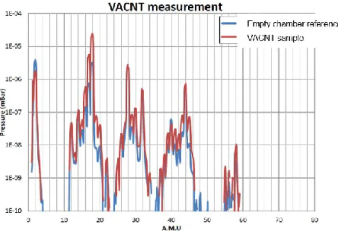
One requirement for qualifying a black coating for optical space application is to demonstrate its ability to remain stable under high vacuum conditions [3]. To evaluate this feature, we placed one of our VACNT sample into a low pressure chamber pumped down to a residual vacuum of 10-5 mbar and analysed the residual gases by mass
spectrometry (SRS RGA mass spectrometer). We then compared the results with the same system without the VACNT sample (empty chamber reference). The results are shown on Fig. 8.
3E-04 lE-05 1E-06 d1E-07 1E-08 1E-09 1E-10 0 VACNT measurement
Ì
- Empty chamber reference VACNT sample
10 20 30 40 50 60 70 80
A.M.0
Fig. 8. Residual gas analysis spectra of the vacuum chamber with (red) and without (blue) VACNT sample.
The nitrogen peak (at AMU 28) is taken for reference to scale the spectra. No heavy compound (AMU > 45) is detected and no significant difference is observed between the two spectra, thus validating the ability of VACNT to sustain secondary vacuum conditions without outgassing.
V. CONCLUSION
We have reported the synthesis of Vertically Aligned Carbon Nanotube (VACNT) black coatings from aerosol assisted atmospheric pressure CCVD process. Based on this process, the continuous roll-to-roll production of large area coatings at high cost-efficiency and manufacturability is currently being implemented at pilot-line level. The total hemispherical reflectance of these films is below 2% and the specular reflectance is below 0,02% for most samples at wavelength above 400nm. The transferability of the VACNT films on a destination substrate has been demonstrated, this transfer being accompanied by an improvement of the low reflexion properties (decrease of the reflectance). Further reduction of the reflectance has been obtained by plasma etching. No outgassing has been detected under secondary vacuum conditions as required for space optics applications.
ACKNOWLEDGEMENTS
All the team at Amplitude Technologies (Evry, France) is gratefully acknowledged for the outgassing tests. REFERENCES
[1] C Castro, M Pinault, D Porterat, C Reynaud, M Mayne-L’Hermite, “The role of hydrogen in the aerosol-assisted chemical vapor deposition process in producing thin and densely packed vertically aligned carbon nanotubes” Carbon 61 (2013) 585-594
[2] P. Boulanger, Nanosafe 2012: International Conferences on Safe Production and Use of Nanomaterials, Journal of Physics: Conference Series 429 (2013) 012050
[3] E. Theocharous, C. Chunnilall, R. Mole, D. Gibbs, N. Fox, N. Shang, G. Howlett, B. Jensen, R. Taylor, J. Reveles, O. Harris, and N. Ahmed, “The partial space qualification of a vertically aligned carbon nanotube coating on aluminium substrates for EO applications,” Opt. Express, vol. 22(6), pp. 7290-7307, 2014. [4] B. D. Wood, "Optical Characterization of Carbon Nanotube Forests" (2015). Utah State University. All
Graduate Theses and Dissertations, Paper 4567.
[5] M. A. Quijada, J. G. Hagopian, S. Getty, R. E. Kinzer and E. J. Wollack, “Hemispherical Reflectance and Emittance Properties of Carbon Nanotubes Coatings at Infrared Wavelengths” Proc. of SPIE Vol. 8150 815002-2.
[6] S.Lagoutte, P.-H. Aubert, M. Pinault, F. Tran-Van, M. Mayne-L’Hermite and C. Chevrot, “Poly(3-methylthiophene)/Vertically Aligned Multi-walled Carbon Nanotubes: Electrochemical Synthesis, Characterizations And Electrochemical Storage Properties In Ionic Liquids” Electrochimica Acta 130 (2014) 754–765.