by
Timothy David Koch
SUBMITTED TO THE DEPARTMENT OF MECHANICAL ENGINEERING IN PARTIAL FULFILLMENT OF THE REQUIREMENTS FOR THE DEGREE OF
BACHELOR OF SCIENCE AT
MASSACHUSETTS INSTITUTE OF TECHNOLOGY
JUNE 2007
@ Timothy Koch. All rights reserved.
The author hereby grants to MIT permission to reproduce and distribute publicly paper and electronic copies of this thesis document in whole or in part in any medium now known or hereafter created.
Signature of Author:
Department of Mechanical Engineering
May 11, 2007 Certified by: Accepted by: MASSACHUSETTS INSTITUJTE OF TECHNOLOGY
JUN
2
1 2007
Marilyne Andersen or of Building Technology o .Lienhard Vsor of Mechanical Engineering Chairman, Undergraduate Thesis Committee
by
Timothy David Koch
Submitted to the Department of Mechanical Engineering on May 11, 2007 in
partial fulfillment of the requirements for the Degree of Bachelor of Science in
Engineering as recommended by the Department of Mechanical Engineering
ABSTRACTTo enable the fast and accurate cataloging of material samples, I designed
a filtration device for selecting specific visible and near-infrared light
wavelengths related to the red, green, and blue sensitivity peaks of a visible
detection camera and the pixel response for a near-infrared camera. This filter
device functions in conjunction with the Department of Architecture's
Daylighting Laboratory goniophotometer to profile the complete reflection and
transmission properties for sample building materials. The resulting data is used
in computer simulations and material optimization.
The goniophotometer uses two types of detection cameras, color and
infrared, to measure the light that is transmitted or reflected off a sample of
material. The spectral sensitivity variances of the cameras create inaccuracies in
the resulting data when full-spectrum light is used. To remove these
inaccuracies, the light is filtered into smaller sections of the full spectrum and the
data is recombined by software, to remove these inaccuracies. The device to filter
the light is the subject of this thesis.
The final filter design uses a geneva drive to index wheels containing pairs
of high-pass and low-pass filters into the light path between the light source and
the test specimen. The device satisfies the design specifications dictated by the
usability, function and spatial constraints. This design should prove to be very
reliable and flexible through its continued use in studying building materials. As
the project is advanced, future woirk includes installation of the control system
and integration into the softwareuised to coordinate the goniophotometer
components.
Thesis Supervisor: Marilyne Andersen
Title: Assistant Professor of Building Technology
5/11/2007
TABLE OF CONTENTS ABSTRACT . ... . ... 2 TABLE OF CONTENTS ... ... ... ... 3 1. INTRODUCTION ... ... *** *.***** so** * .. 8069600*6699 .. 4 2. BACKGROUND . ... .... ... ... *... 5 2.1 Goniophotometers ... ... 5 2.2 Camera Sensitivity ... ... 7 3. DESIGN PARAMETERS ... ... ... 7 4. FORM FACTORS ... 8
5. DRIVE SYSTEM CONCEPTS ... ... ... 9
5.1 Spur Gear ... ... 9
5.2 Non-circular Gear... ... 10
5.3 Worm Gear ... 11
5.4 Geneva Drive ... 11
6. FILTER W HEEL DESIGN... . ... 12
7. GENEVA DRIVE DESIGN ... 14
7.1 Output Wheel... 14
7.2 Drive Wheel ... ... 14
8. FRAME DESIGN ... ... 16
9. PRODUCTION AND ASSEMBLY ... . ... 16
10. FUNCT.ION BEHAVIOR ... ... 17 11. CONCLUSIONS ... ... 19 11.1 Design Goals ... 19 11.2 Material Selection ... 19 11.3 Mechanical Failure... 19 11.4 Future Work ... 20 12. REFERENCES ... 21
1. INTRODUCTION
Proper interior lighting is essential for creating a high quality of life. Using natural sunlight for illumination has many environmental and economical advantages over electrical lighting alternatives. Buildings that utilize natural solar light can rely less on electricity, lessening their energy footprint. In addition to direct savings from not turning on lights, using fewer electric lights reduces internal heat gains, decreasing cooling loads, a major part of a building's energy use. Heat from solar gain itself can even be used in winter months to replace a portion of a heating load, increasing savings further. As building owners realize the cost advantages of daylighting and building tenants discovering the productivity benefits of natural light, the market for effective solar use is increasing rapidly (Leslie, 2003). The interest in natural lighting in buildings has fueled the research of fenestration systems that provide desired results for filtering and distributing light through workspaces.
To study these materials, the MIT Daylighting Laboratory has developed a goniophotometer. The goniophotometer shines light on a sample of building material and measures the direction and magnitude of the light leaving the surface of the sample. This apparatus consists of a fixed light source and a rotating table on which the material sample, a reflective dome and a calibrated camera equipped with a fish-eye lens are mounted. Detection cameras inherently have characteristic sensitivity peaks, corresponding to the CCD camera's red, green and blue channels (visible light range) and to the near-infrared (NIR) camera's pixel response. When data from the entire spectrum is analyzed at once, no spectral information about transmitted or reflected light can be produced although that kind of information can be critical for energy-efficient windows. Since both cameras' spectral sensitivities vary over the considered wavelength range, incoming light needs to be filtered before analysis. The device for selecting light wavelength ranges assists in the profiling of building materials for their light properties to provide more complete material information. The
device uses a geneva drive to rotate a series of light filter pairs into the light path letting a small band of the visible or near-infrared spectrum pass through to the
5/11/2007
materials, many different designs can be generated and studied quickly
(Andersen and De Boer, 2006).For this purpose, the MIT Daylighting Laboratory has built a
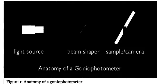
goniophotometer (Andersen et al., 2005). The current setup (Figure 1) includes a
full spectrum light source, beam shaper, a measurement table, a light detection
system, and a computer orchestrating the system. The light detection system
consists of a half-ellipsoid attached to the table with the sample at one focus and
a calibrated camera with a fish-eye objective at the other. By the geometry of the
half-ellipsoid, all of the light leaving the sample's surface is reflected into the
camera's fish-eye lens with a unique angle. This is a substantial benefit of the
Daylighting Laboratory goniophotometer over other existing apparatuses. By
using the reflective half-ellipsoid and a fisheye camera lens, every reflected angle
can be analyzed at one time instead of moving the detection device to each
location to take a measurement. The computer receiving the camera's image
interprets the picture as intensity values with angles. When repeated at different
angles, a comprehensive assessment of the material is generated.
sample material. As the project continues, the device will be seamlessly
integrated into the testing setup and become part of the material characterization process. Ultimately understanding material properties will lead to optimized materials and more efficient building envelope assemblies.
2. BACKGROUND
Modeling the behavior of light passing through complex fenestration systems either requires advanced measurement and calculation methods or the building of full-scale mock-ups of the finished window systems. One of the biggest hurdles to accurately predicting the performance of these window systems is the lack of a reliable and systematic characterization of the building materials in a common format. Once an extensive database of material properties is available, both window components manufacturers and building engineers will be able to optimize the performances of their products via computer simulation. A simulation works by calculating the path light takes in a given environment. Every time light bounces off or passes through a surface, known as a bounce iteration, it is sent in new directions with varying intensities. With a modem personal computer, the average room can be modeled very accurately with complex material behaviors, detailed physical models, and many bounce iterations when using advanced ray-tracing tools such as Radiance (Ward and Shakespeare, 1998). It is thus important to correctly identify and optimize the light properties of materials. Special devices, called goniophotometers, have been designed to aid in the characterization of materials to be used in building envelopes.
2.1 Goniophotometers
Goniophotometers measure light transmitted through or reflected off of materials. The device returns an intensity along every emerging direction for a given incident light angle. By collecting a series of incident light angles the properties of the material under study can be known. With accurate material properties, new window designs and materials can be studied in detail without ever having to build an actual window mock-up, and with a vast library of studied
5/11/2007
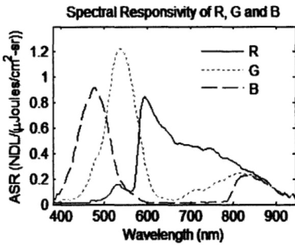
2.2 Camera Sensitivity
This information, however comprehensive, lacks a certain detail. The data are for the full visible and near-infrared spectrum, and the detection cameras are not equally sensitive over the entire spectrum as shown in Figure 2. To account for this varied sensitivity, I have designed a device to filter the light as it leaves the full-spectrum source. The device selects filter pairs in sequence producing narrow frequency bands corresponding to regions of varying camera sensitivity. The filtered light then passes through to the material and onto the camera. The computer interprets these data sets to compile a comprehensive material profile.
Spectral Responsivity of R, G and B
S1.2 R
"E
---
G
1.. Gt 0.6
o0.4 /
0 400 500 600 700 800 900 Wavelength (nm)Figure 2: Absolute spectral responsivity of the red, green, and blue channels of the color detection camera. (source: Gayeski and Andersen, 2007)
3. DESIGN PARAMETERS
The design for the filter device is constrained by certain fixed parameters. By talking with the goniophometer creators and potential users, I identified three governing
constraints: geometric size limits, number of filters, and selection flexibility. As seen in Figure 3, the available space for the filtering device is the two-foot gap between the light
source and beam shaper. The light source is
12 cm in diameter and is fixed at twenty I Figure 3: Filter device space constraints
inches off the floor, requiring the active filter and only the active filter to be located in this space between the light and table. The estimated number of filters is eighteen or fewer, and they are always selected in the same sequence. While not a constraint, the need for computer control with minimal user attention is an important consideration for designing.
Other people working on the project specified the filters (Gayeski and Andersen, 2007). The project is using 15-centimeter diameter colored glass filters from Schott Glass. The filters are used in pairs. One filter in each pair acts as a high-pass filter while the other acts as a low-pass filter leaving a narrow band of the spectrum passing through. Each filter pair weighs approximately 1.2 kg.
4. FORM FACTORS
With these constraints in mind, I looked for examples of previous work in light filtering. Theater makes the most obvious use of light filtering to create environments on stage. Since theaters use
thin plastic gels for most of their filters, many mechanisms are impractical for use
with our glass filters, however, two
devices stand out as potential candidates:
spotlights and color wheels. Manyspotlights have the ability to change their color by a series of colored plates (Figure 4) inside the spotlight. Levers on the
utsiUdU oI Ulut spotlgh tcase operawLt: acu
plate. This is a good design for the long form-factor of the spotlight and the needed flexibility to randomly select and mix filters. With the large number of filters for the goniophotometer application, a device using this form would be longer than the two feet allowed. Also, since the filters are not randomly selected
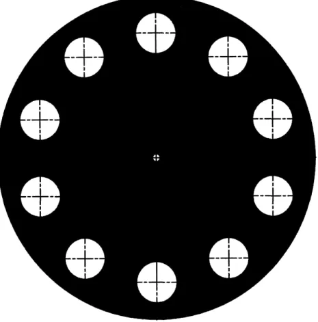
or mixed, a device in this configuration would be larger and more expensive than the project allows. Color wheels (Figure 5), disks with filters mounted in holes
around the edge, are taller and wider than they are deep. Since the color wheel rotates in a particular order it naturally lends itself to selecting filters in order.
5/11/2007
Both of these features, coupled with the cheaper cost of production, makes a filter wheel based system idea for this light filtering task.
one filter lef open to use use a second wheel
edge
Figure 5: Indexed filter wheels 5. DRIVE SYSTEM CONCEPTS
I
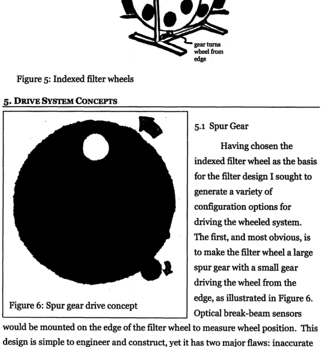
5.1 Spur Gear
Having chosen the indexed filter wheel as the basis for the filter design I sought to generate a variety of
configuration options for driving the wheeled system. The first, and most obvious, is to make the filter wheel a large spur gear with a small gear driving the wheel from the edge, as illustrated in Figure 6. Figure 6: Spur gear drive concept
Optical break-beam sensors would be mounted on the edge of the filter wheel to measure wheel position. This design is simple to engineer and construct, yet it has two major flaws: inaccurate positioning and rotational inertia. A wheel, with nine, 1.2 kg filter pairs has a
large rotational moment of inertia, which could over-power the drive motor when in motion causing the filter wheel to overshoot a filter position. To counter act this, the wheel would need to be driven at an angular velocity so as to avoid developing enough momentum to over power the drive motor. To compensate, the filter transition time would be long or the motor would be larger. The other cause of inaccurate positioning is in the nature of optical sensors. The slit in the wheel for the sensor would be between a half and one degree wide, leading to an equal degree of error in filter selecting. In the next iteration I looked for ways of limiting the moment of inertia's effect on the wheel's motion by the system's design.
V
Non-crmculanr a Ir
By slowing down the filter wheel's motion as it approaches
the next position, the effect of
momentum could be limited
while maintaining acceptable
filter change times. By using a
non-circular gear (Figure 7) the
drive motor rotates at a constant
speed, while a decreasing gear ratio causes the filter wheel tomove quickly at the beginning of Figure 7: Non-circular gear concept a filter change and gradually slow
as it approaches the next stopping point. This design limits the effects of rotational inertia on back driving the motor, but it is a challenge to implement. Non-circular gears are very difficult to design properly as their curves and teeth
must match perfectly throughout the changes in the rotation cycle. Another way to address this problem is to focus on preventing back-drivability all-together while leaving the rotational momentum unchanged.
5/11/2007
5.3 Worm Gear
To address the root issue of back driving I looked to using worm gear. A worm gear (Figure 8) is a spiral column that turns a spur gear when it is rotated. Its advantage over a spur gear is that the output wheel cannot cause the driving worm gear to rotate, known as back-driving. It is a one-way transfer of motion. A worm gear setup like the one illustrated in Figure 8 is impractical due to the cost of such a large worm gear, however, a system could use a drive gear box that has a worm gear in it. The motor would drive the gearbox that drives a small spur gear that is in a
similar configuration as Figure 6. This design effectively solves the back drive issue, but still does not address the inherent inaccuracy in using optical sensors to index the filter wheel. The root problem with each of these designs is that they are designed for motion but not intermittent
Snti"nn
5.4 Geneva Drive
For a truly robust solution, the drive system must be constrained by geometry to index exactly one filter set each time it is activated. For inspiration I turned to the engineering library's collection of books on machine design,
specifically devices for intermittent motion. Clocks, production lines, and engines all use some form of intermittent motion using cams, sprockets, and springs. After reviewing the various devices, one really stuck out as a potential design for the filter wheel, the geneva drive (Jensen, 1991). Geneva drives are
popular in manufacturing for turning a continuous rotational input into an indexed output motion. The inspiration diagram used a four-position output wheel with a larger drive wheel. By reversing the size ratio, a similar motion can
be implemented for a ten-position filter
wheel (Figure 9). In a geneva drive, the drive wheel has a pin that moves the output wheel one step each time it makes one rotation. The drive wheel also features a raised circle that works to lock the output wheel when the pin is not in a slot. Because of the geneva drive's accuracy and low cost it was chosen as the best solution for the filter Figure 9: Geneva drive concept device's drive system.
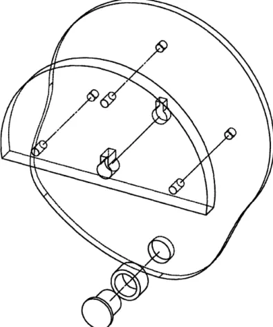
6. FILTER WHEEL DESIGN
The filter wheel (Figure lo) is the central component for this device. As such, the entire device design stems from the filter wheel. The wheel is designed to position one filter twenty inches off the floor. With a two-inch border, the bottom of the wheel is designed to be two inches off the floor. From there, the midpoint of the wheel is defined, and the lens position is repeated around the circle ten times. Since ten filter openings is not enough for the estimated eighteen filter pairs, two wheels are used in series. One filter spot in each filter wheel is left blank to allow the light to pass through unobstructed when the other filter wheel is in use.
5/11/2007
Figure 11: Filter wheel design showing to filter locations The filters are held in place by
screws through three rubber side-supports and a top, retaining ring
(Figure 11). The rubber supports are
sized to be slightly longer than the lenses are thick so that, when
tightened, the rubber supports expand to squeeze the lens edge. Some filter
spots only use a single filter, so a I Figure 11ii: Filter mounting assembly spacer is available to fill the gap in the
filter assembly. In addition to the holes for mounting the filters, the filter wheel has five holes to attach to the output wheel of the geneva drive. The entire filter
wheel is designed to be laser or water-jet cut out of a single sheet of quarter-inch thick ABS plastic. The necessary holes are tapped to accept the screws after cutting the part out.
7. GENEVA DRIVE DESIGN
-i A L~. . 7.1 Output Wheel
The geneva drive is designed to work with the filter wheel to produce the indexed motion the project requires. The output wheel (Figure 12) mounts to the filter wheel on five, two-inch aluminum spacers. These spacers lengthen the shaft bearing through the two wheels to avoid wobbling
U UVU
I U
Figure 12: Geneva dive output wheel
wheel to operate without
contacting the filter wheel. The output wheel has ten index points to match the
filter locations and is sized so as to not interfere with the line-of-sight from the
light to the table. The size of the output wheel dictates the design of the drive
wheel.
7.2 Drive Wheel
The drive wheel, Figure 13, is an assembly of five parts: base, raised
semicircle, peg, and peg tube. The raised circle fits into the corresponding space
in the output wheel, and the pin slides into the slots. The drive wheel is a
four-piece assembly (Figure 13). The base and raised circle four-pieces are cut from
quarter-inch-thick ABS plastic and screwed together. The pin is made from a
turned plastic peg that is epoxied into the base. A retaining lip at the top of the
peg secures an aluminum tube that is free to rotate about the peg, reducing the
wear of the pin against the walls of the output wheel's slots. This assembly has a
5/11/2007
keyway to transfer the rotation from the drive motor shaft. The base section's
irregular shape is for a roller switch to monitor the wheel's rotation counts.
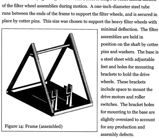
8. FRAME DESIGN
The frame (Figure 14) uses a welded steel A-shape to resist lateral motion of the filter wheel assemblies during motion. A one-inch-diameter steel tube runs between the ends of the frame to support the filter wheels, and is secured in place by cotter pins. This size was chosen to support the heavy filter wheels with minimal deflection. The filter assemblies are held in
position on the shaft by cotter pins and washers. The base is
a steel sheet with adjustable feet and holes for mounting brackets to hold the drive wheels. These brackets include space to mount the drive motors and roller switches. The bracket holes for mounting to the base are
slightly
oversized to account
Figure 14: Frame (assembled) for any production and assembly defects.
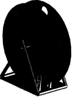
9. PRODUCTION AND ASSEMBLY
Wherever possible, pieces have been designed for computer-controlled production such as laser and water-jet cutting. Once all of the pieces have been produced, assembly begins with the frame. The steel frame pieces are welded,
and the adjustable feet are installed on the bottom. Next, the filter assemblies are put together as illustrated in Figure 11. The filter wheels and spacers are installed on the shaft and pinned in place. Lastly the drive wheel is attached to its
mounting bracket along with the drive motor and roller switch.
5/11/2007
Figure 15: Filter device fully assembled
10. FUNcrloN BEHAVIOR
During operation, each filter wheel is advanced forward (Figure 16) on the
command of the control computer. When it's first turned on, the device control
system will check to ensure each filter wheel is positioned with the empty filter
spot in the "active position" using optical sensors. If a wheel is not in this starting
system, the drive motor is activated, indexing the wheel forward. Once the
system is ready to take a set of readings (sample is mounted on the table, camera
is ready, table is in location, etc.), drive motor number one is activated, turning
the drive wheel and indexing the filter wheel one spot. As the drive wheel rotates
to where the pin is in the slot, the roller switch that rides on the outer edge of the
drive wheel is released. The motor remains active until the filter wheel has
completed its advancement, signaled by the roller switch being depressed again.
The computer now takes the readings from the detection camera. When the
readings are finished, the control system repeats the filter advancement process.
After all of the filters in wheel one have been used, wheel one is returned to its
initial "open" position and the advancement procedure is continued with filter
wheel two. When all readings are performed, both wheels are returned to their starting orientation.
1. Drive wheel rotates clockwise 2. Drive pin enters slot, raised
semicircle leaves contact
3. Filter wheel rotates counter- 4. Drive pin exits slot, semicircle
clockwise constrains filter wheel
Figure 16: Filter wheel advancement sequence
5/11/2007
11. CONCLUSIONS
11.1 Design Goals
This project has proved a challenging undertaking in spite of its relatively simple design parameters. The biggest challenge was certainly developing a drive system that accurately and reliably changes filters without user supervision. A complete testing cycle could take many hours to complete, making it important to need minimum attention from a user during operation. The geneva drive should prove to be a good choice for the filter device. Its main advantage over the other geared solutions is how its positions are defined by the geometry of the drive and output wheel rather than relying on optical sensors. Where the geared systems would experience slight inaccuracies with each filter change, the geneva system will not.
11.2 Material Selection
Material choice was an optimization exercise balancing cost, weight and reliability while meeting the part specifications. The steel frame is stiff and heavy to keep the filter wheels in place. The cyclic loads placed on the frame by the wheel rotations are sufficiently low to avoid fatigue, so the frame should virtually last forever. The polymer wheels, on the other hand, are designed to keep weight and cost down. The wheels are subjected to very low strain allowing for many cycles before failure (cycles to failure > io,ooo). Since one cycle for the filter wheel equals ten cycles for a drive wheel, the drive wheels a likely to fail well before the filter wheels.
11.3 Mechanical Failure
The eventual reality of failure influenced the decision to produce as many components as possible out of flat sheets cut on a laser cutter or water jet
machine. When a part fails, a replacement part can be fashioned quickly by retrieving the necessary file and cutting another out of a material sheet. This is
an intentional design choice in keeping with the need for low "cost-of-ownership."
11.4 Future Work
As the project continues it will be integrated into the computer control system for seamless use. An onboard controller board will control the motors, getting feedback on the filter wheel locations from optical break-beam and roller switches. To enable future use, the device is designed with flexibility in mind. The adjustable feet in the base allow it to be leveled and height-adjusted when necessary. In addition, the filters are accessed easily to allow for changes in the number and types of filters needed. For example, if a different camera were used in the future, a new set of filters would be necessary.
With the filter device's completion and integration into the
goniophotometer setup, the library of material properties will grow with ease. This library will surely prove invaluable to architects and building engineers as a design tool. As this library expands to include innovative materials, even more possibilities for efficient building designs become available, allowing us to reduce our impact on the earth and its environment without sacrificing comfort or functionality.
5/11/2007
12. REFERENCES
Andersen, M., De Boer, J.. "Goniophotometry and assessment of bidirectional photometric properties of complex fenestration systems." Energy and
Buildings. Volume 38. 200oo6. Pages 836-848.
Andersen, M., Ljubicic, D., Browne, C., Kleindienst, S., Culpepper, M., "An automated device to assess light redirecting properties of materials and perform sun course simulations: the Heliodome project", In Proceedings
of the ISES 200oo Solar World Congress - Bringing Water to the World, Orlando, August 6-12, 2005.
Gayeski, N., Andersen, M., "New Methods for Assessing Spectral, Bi-directional Transmission and Reflection by Complex Fenestration Systems." In Proceedings of SOLAR 2007: Sustainable Energy Puts America to Work,
Cleveland, July 7-12.
Jensen, Preben W. Classical and Modern Mechanisms for Engineers and Inventors. Marcell Dekker, Inc. New York, New York. 1991.
Leslie, R. P. "Capturing the daylight dividend in buildings: why and how?"
Building and Environment. Volume 38, Issue 2. February 2003. Pages
381-385.
Ward G., Shakespeare, R. "Rendering with RADIANCE. The Art and Science of Lighting Visualization", Morgan Kaufmann Publishers, 1998.