HAL Id: hal-00812139
https://hal.archives-ouvertes.fr/hal-00812139
Submitted on 11 Apr 2013HAL is a multi-disciplinary open access archive for the deposit and dissemination of sci-entific research documents, whether they are pub-lished or not. The documents may come from teaching and research institutions in France or abroad, or from public or private research centers.
L’archive ouverte pluridisciplinaire HAL, est destinée au dépôt et à la diffusion de documents scientifiques de niveau recherche, publiés ou non, émanant des établissements d’enseignement et de recherche français ou étrangers, des laboratoires publics ou privés.
A microfluidic technique for generating monodisperse
submicron-sized drops
Yann Yip Cheung Sang, Elise Lorenceau, Sebastian Wahl, Maximilien Stoffel,
D. E. Angelescu, Reinhard Höhler
To cite this version:
Yann Yip Cheung Sang, Elise Lorenceau, Sebastian Wahl, Maximilien Stoffel, D. E. Angelescu, et al.. A microfluidic technique for generating monodisperse submicron-sized drops. RSC Advances, Royal Society of Chemistry, 2013, 3 (7), pp.2330. �10.1039/c2ra23090a�. �hal-00812139�
A microfluidic technique for generating monodisperse
submicron-sized drops
1,2
Yann Yip Cheung Sang, 3Elise Lorenceau, 4Sebastian Wahl, 4Maximilien Stoffel ,4Dan Angelescu,
5,2
Reinhard Höhler*
1
Université Paris Diderot, Laboratoire Matière et Systèmes Complexes, UMR 7057 CNRS 10, rue Alice Domon et Léonie Duquet, 75205 Paris Cedex 13, France
2
Université Paris-Est, Laboratoire Physique des Matériaux Divisés et des Interfaces, EA 7264, 5 Bd Descartes, 77454, Marne-la-Vallée, France
3
Université Paris-Est, Laboratoire Navier, UMR 8205 CNRS, 2 Allée Kepler, 77420 Champs sur Marne, France
4
Université Paris-Est, Laboratoire ESYCOM - ESIEE, 2 Bd Blaise Pascal, 93162 Noisy le Grand, France
5
Université Paris 6, INSP, UMR 7588 CNRS-UPMC, 4 place Jussieu, 75252 Paris Cedex 05, France
AUTHOR EMAIL ADDRESS [email protected]
We present a route for producing monodisperse micro and nanodrops that is based on a liquid-gas phase transition occurring within a microfluidic device. A gas which is soluble in water is mixed with an insoluble one and injected into an aqueous surfactant solution, using a microfluidic device that produces monodisperse bubbles. As the soluble gas diffuses out of the bubbles, they shrink and the remaining
insoluble gas condenses into drops. Their radius can be tuned over a wide range by changing the initial gas mixing ratio.
1. Introduction
Drops with sizes of the order of 100 nm are used as templates for photonic crystals1, in bio-medical applications such as drug delivery2 and for imaging3. Such drops can carry substances or nanoparticles and their interfaces can be functionalized to bind to specific biological targets. Perfluorocarbon liquids drops are of particular interest for medical applications, because of their biocompatibility2b,3. In many cases, accurate control of the size is crucial: It must be small enough for the drops to pass through biological membranes and to avoid destruction by macrophages. In templates for photonic crystals, the lattice constant of the droplet packing must be matched to the light wavelength. Monodisperse nanodrops can be obtained by fractionation and shear rupture techniques, but they require extremely high shear rates and their efficiency depends on the phase diagram of the surfactants chosen to stabilize the emulsion4. As an alternative to emulsification based on shear-induced rupture, various microfluidic devices producing monodisperse drops and bubbles have been developed in recent years5. However, the smallest droplet sizes obtained by such devices are generally of the order of a micrometer6. Recently, submicron droplet production using a microfluidic device operating in a tip-streaming mode was reported, at a rate of several hundreds of droplets per second7.
In this paper, we present a proof-of-concept experiment that validates a new approach for making monodisperse microdrops, and we show that it offers the perspective of making nanodrops at a high rate. We first prepare an aqueous surfactant solution and a mixture of two gases: one is highly soluble in water (carbon dioxide), the other is an almost insoluble perfluorocarbon vapor (perfluorohexane). Liquid and gas are injected into a microfluidic device that produces monodisperse microbubbles. The soluble component of their gas content diffuses into the neighboring liquid whereas the perfluorocarbon vapor remains trapped. As the bubbles shrink, the vapor is increasingly compressed. This effect is enhanced by the Laplace pressure, which scales as the inverse of bubble radius. When the
perfluorocarbon gas pressure in the bubbles reaches the equilibrium vapor pressure, condensation sets in, the bubbles collapse, and micro- or nanodroplets are formed. The size-reduction ratio relating the initial bubble and the final droplet depends on the composition of the initial gas mixture and can therefore be tuned freely over a wide range, for a fixed device geometry, pressure and temperature. Controlled shrinkage of bubbles in a microfluidic device, due to diffusive gas transfer to the surrounding liquid, has been reported previously as a method for making monodisperse microbubbles. In this latter work8, the extent of dissolution of bubbles in the device was controlled by the saturation of the continuous aqueous phase with gas. By analogy, one might attempt to reduce the size of drops by letting their content diffuse into the surrounding phase. In the case of perfluorocarbon drops dispersed in water, this approach is hopeless since this material is almost totally insoluble in water. Therefore, our method based on a phase transition transforming bubbles into droplets is a major extension of previous techniques.
2. Theoretical background
Bubble shrinkage due to gas diffusion has been modeled in the literature9, but in the case where the gas contained in the bubble is a mixture of a soluble and an insoluble component one has to consider an additional effect, the osmotic pressure opposed to the transfer of the soluble gas species out of the bubble. This contribution was not taken into account in previous theoretical analyses9. On the basis of a closely analogous calculation for emulsion droplets containing an insoluble species10, we derive the following time evolution of the bubble radius R from the equality of chemical potentials for the soluble gas inside and outside the bubble, the Laplace equation and the diffusion equation:
0 3 0 0
3
2
(
4 / 3 )
4
η
σ
ε
σ
π
=
+
−
+
B o
B
D k T c
k T
dR
P
dt
R P P
R
R
R
(1)σ is the tension of the bubble interface, P0 the ambient pressure in the liquid, T the temperature, η the
number of insoluble molecules contained in the bubble, D the diffusion constant for these molecules in the liquid and ε, the degree of saturation of the liquid with the soluble gas, defined as
0
0
c
c
c
ε
=
−
(2)c
denotes the average concentration of the soluble species in the liquid and c0 the solubility (the largestpossible concentration) of this species. ε ranges from -1 (no dissolved gas) to 0 (maximum gas concentration). The three terms on the right hand side of Eq. (1) represent respectively the effects of 1) the liquid pressure P0 pushing on the bubble, modulated by the saturation parameter ε to take into
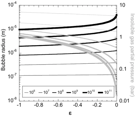
account the dissolved gas, 2) the osmotic pressure, proportional to η, that tends to dilute the insoluble species and to keep therefore the soluble gas in the bubble and 3) the Laplace pressure, due to surface tension, that tends to squeeze the gas out of the bubble to minimize interfacial energy. Eq. 1 shows that in the presence of an insoluble species, bubble shrinkage is slowed down and it can stop at an equilibrium size, determined by solving this equation with dR/dt = 0. The dependency of this equilibrium bubble radius on η and ε is illustrated on Figure 1. By comparing the partial pressures of the insoluble species in the bubble (considered as an ideal gas) to the vapor pressure of this species one can predict whether shrinking bubbles will first reach an equilibrium state or collapse into droplets. The vapor pressure of C6F14, the insoluble species used in our experiments, is 0.31 bar at 25 °C 9a. Figure 1
shows that in this case, collapse is ensured if the liquid is weakly saturated by the soluble gas (ε close to -1), a condition also required for fast shrinkage (cf. Eq. 1). However, for ε approaching zero, collapse can be inhibited. Figure 1 indicates that if C6F14 gas is used, this situation can only occur for η > 108 and that therefore, the effect cannot prevent the production of submicron droplets. Perfluorocarbon gases with fewer carbon atoms per molecule have much larger vapor pressures9a (28 bar at 25 °C for C2F6),
agreement with experiments11. We note that over long times, such bubble dispersions coarsen, due to the solubility of C2F6 in water which is much larger than that of C6F14.
106 107 108 109 1010 1011 10-8 10-7 10-6 10-5 10-4 0.01 0.1 1 10 -1 -0.8 -0.6 -0.4 -0.2 0 B u b b le r a d iu s ( m ) In s o lu b le g a s p a rti a l p re s s u re ( b a r) ε
Figure 1 The equilibrium bubble radius predicted by Eq. 1 (black lines) and the partial pressure of the
insoluble species (grey lines), considered as an ideal gas, are both plotted versus the degree of saturation ε of the liquid with the soluble gas, defined in Eq. 2. Increasing line thicknesses distinguish the number of insoluble gas molecules per bubble, as specified in the insert. The calculations are performed for a temperature of 298 K and an interfacial tension of 37.5 mN/m.
3. Experiments
Figure 2 illustrates our experimental setup. To prepare the gas mixture, we first evacuate a reservoir (volume: 1.2 l) with a vacuum pump. Then, we use a microsyringe to inject a controlled amount of liquid C6F14 into the reservoir via a septum. This perfluorocarbon liquid has a vapor pressure of 0.31 bar at 25°C 9a and it evaporates rapidly upon injection. We add CO2 gas until a total pressure of 2 bar is reached.
This gas mixture is homogenized using a fan located inside the reservoir. The aqueous solution used in our experiment is a 50% by weight mixture of glycerol and purified water (Millipore) to which
9.4 10-3 g/g of the surfactant tetradecyltrimethylammonium bromide (Aldrich) and 6.24 10-6 g/g of dodecanol (Aldrich) are added, and which is filtered and carefully degassed in a vacuum chamber prior to use. Due to the low concentration of CO2 in air, degassing is not obviously a critical issue. However, if
nitrogen were dissolved in the liquid, it would be absorbed by the bubbles which initially contain only CO2, due to an osmotic pressure effect similar to the one discussed above. As a consequence, bubble
shrinkage can be slowed down or even stopped. The interfacial tension of our foaming solution was measured using the pendant drop method and found to be 37.5 mN/m, at a temperature of 22 °C.
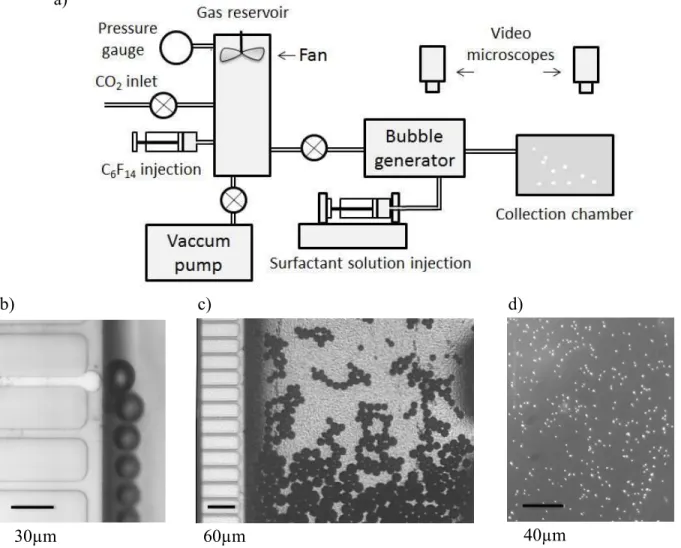
Figure 2: a) Schematic view of the experimental setup b) Bubble production in a single channel of the
micro-fabricated bubble generator. c) Bubble production and onset of shrinkage in the generator. The horizontal channel that looks white is filled with gas and produces bubbles, due to an instability driven by capillary forces. The other horizontal channels are not active in this experiment. d) Perfluorocarbon droplets observed in the collection chamber.
b) c) d)
a)
The solution and the gas mixture are injected into a microfluidic bubble generator. In a first set of experiments, we used a generator that we have described previously12 and which produces monodisperse bubbles with a radius of 45 µm. They were injected into a transparent collection cell previously filled by the solution described above. The cell was constantly stirred to prevent bubbles from accumulating at the top. In regions where bubbles accumulate, the saturation parameter ε would locally reach values approaching zero. Equation 1 and Figure 1 show that under these conditions, bubble shrinkage stops. The experimentally observed transformation from bubbles to drops typically took 3 minutes. To reduce this time, a smaller initial bubble size is required. In a second set of experiments we used a microfabricated foam generator that we recently described in full detail13 and that is similar to a microchannel emulsification device 14. In this second case, the bubbles had an initial radius close to 10 µm, with a standard deviation on the order of 1%, and we were able to implement bubble collapse and drop production as a steady process: The bubble suspension was continuously produced and transferred into a collection chamber, via a capillary whose length is 20 cm. At the end of this transit which lasts approximately 30 s for a typical liquid flow rate of 3 ml/h, all the bubbles were found to be already transformed into drops. Two video microscopes were used to observe the bubbles in the microfluidic device and the drops arriving in the collection cell.
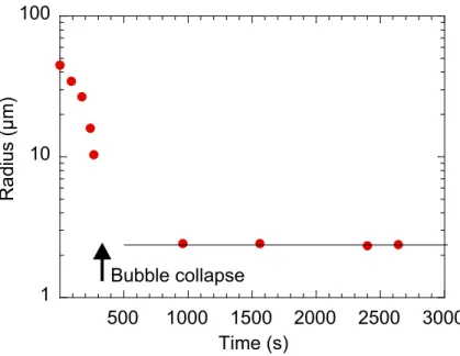
Figure 3 Typical time evolution of bubble and droplet sizes, observed in the collection chamber of the
first experimental configuration described in the text. The bubbles shrink and finally collapse into droplets of constant size. The final stages of the collapse are very fast and could not be resolved in our work using the first experimental configuration. This feature was observed using the second setup described in the text, as illustrated in Figure 4.
Figure 4 Two images, taken near the output of the microfabricated foam generator, at a time interval of
5 s illustrate the transformation from bubbles to drops. To avoid convective displacements that carry the bubbles out of the field of view, the gas and liquid injection were stopped just before the observation. Bubbles appear as black disks, whereas drops have a lighter color, as explained in the text.
1 10 100 500 1000 1500 2000 2500 3000 R a d iu s (µ m) Time (s) Bubble collapse
4. Results and discussion
Figure 3 shows a typical time evolution of the bubble radius, observed in the first device described above: bubbles shrink and finally collapse, giving rise to droplets which remain stable for thousands of seconds. Figure 4 illustrates the final stages of the transformation from bubbles to drops, observed in the second device described above, using the microfabricated foam generator. The coefficient of variation that we find for the drops obtained here (radius: 0.7µm) is close to 8%. The increase compared to the 1% coefficient of variation observed for the initially produced bubbles (radius: 10 µm) can to a large extent be attributed to the experimental resolution of our video microscope.
The size of the obtained droplets does not evolve on our experimental time scale. This is in agreement with previous studies of polydisperse aqueous perfluorocarbon emulsions with droplet sizes similar to ours where Ostwald ripening was found to increase the average droplet size only after many days15. Drops can be distinguished from bubbles, because the refractive index of the surfactant solution is much closer to that of liquid C6F14 than to that of air. Therefore, bubbles strongly scatter light and appear as
black disks in Figure 4, whereas droplets scatter light only weakly and their color on the picture appears lighter. Moreover, the bubbles and droplets shown in Figure 4 are associated in clusters. We have observed that this effect can be strongly reduced by decreasing the surfactant concentration, suggesting that the droplet flocculation is due to attractive depletion interactions induced by micelles16.
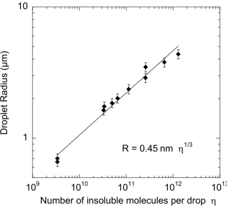
Figure 5 Final drop radius R obtained after bubble collapse versus the number of water-insoluble
molecules η initially contained in the bubbles and finally in the drops. The straight line is a power-law fit to the data, as indicated. The drops with a radius below 1µm were obtained either using the microfabricated bubble generator (initial bubble radius 10 µm) and the other ones with the flow focusing device (initial bubble radius 45 µm), as described in the text. The indicated error bars indicated the typical coefficient of variation.
Figure 5 shows the drop radii R obtained in our experiments as a function of η, the number of insoluble gas molecules per bubble. η is deduced from the known gas composition and the initial bubble size observed in the microfluidic device. For a given molecular volume vm, one expects the relation
η vm = 4πR3/3. The resulting power law R η1/3 is indeed in good agreement with our data over three
orders of magnitude of η. The fitted prefactor 0.45 nm is within 5% of the one expected in view of the molecular volume vm = 3.3 10-28 m3 that can be estimated from the density and molecular weight of
1 10 109 1010 1011 1012 1013 D ro p le t R a d iu s ( µ m )
Number of insoluble molecules per drop η R = 0.45 nm η
C6F1415. These results demonstrate that our new technique, combining conventional microfluidics and
physicochemical effects, can indeed be used to produce monodisperse microdroplets, and that their size can be freely tuned via the concentration of insoluble vapor in the gas, injected into the microfluidic device.
The results shown on Figure 5 raise the question whether there are any fundamental limits to a reduction of the droplet size. Reducing the C6F14 concentration in the gas by an order of magnitude or
more is straightforward, using the setup shown on Figure 2: To dilute a given gas mixture, we reduce its pressure to a small value using the vacuum pump, and we then add CO2 gas to re-establish the original
pressure, required to operate the microfluidic device. We have used this approach to make droplets which contained 4.3 108 molecules of C6F14, and whose radius can be estimated by extrapolating the
data on Figure 4 as 340 nm. We did observe these droplets, but the resolution of our microscope did not allow us to measure their size accurately. The lower limit of stable droplet sizes that can be obtained may be set by the solubility of the perfluorocarbon liquid in water which is very low15 (2.7 10-7 mol/L), but not zero. However, experiments show that perfluorocarbon (perfluorotributylamine) emulsions with droplet diameters of 200 nm can be stable over at least two weeks, so that at least down to this size range, solubility is not a critical issue17. Another important feature is the rate of droplet production. It is only of the order of 102 Hz in our proof of principle experiment, but it can be enhanced by using generators described in the recent literature6a that produce monodisperse bubbles of a radius below 5 µm, at a rate up to 106 Hz. Droplet production at such a rate would be of interest for many biomedical applications. This perspective is an advantage compared to microfluidic submicron droplet production using a specific tip streaming operating mode 7 where the production rate is of the order of 102 Hz.
We finally discuss in what respect the new monodisperse perfluorocarbon droplet production technique that we report will be useful in applications. A monodisperse size distribution greatly reduces the growth of the average droplet size due to Ostwald ripening, an aging process driven by differences in radius (and thus Laplace pressure) among the droplets. If coalescence is suppressed by a suitable choice of surfactants, making highly monodisperse nanoemulsions can thus be an alternative to other more
biomedical applications, such as enhanced oxygen transfer17 which relies on the very large solubility of oxygen in perfluorocarbon liquids17. Applications where droplets must travel through biological membranes are another example where accurate size control is crucial. An example is MRI imaging, where the large NMR activity of the 19F atoms contained in perfluorocarbon atoms is used18 and where the droplet interfaces are functionalized by adsorbed lipid layers and targeting ligands. This functionalization has been demonstrated with perfluorocarbon droplets obtained using other techniques18,
and may therefore also be applied to the nanoemulsions obtained using our setup. This approach where shrinking bubbles give rise to droplets may enhance the adsorption process: the initially large bubble surface area helps to adsorb efficiently substances dissolved in the surrounding bulk liquid to the interface, and upon bubble shrinkage, the surface concentration of these substances will increase strongly.
5. Conclusions
We have demonstrated experimentally a new approach for making monodisperse submicron droplets, based on a liquid-gas phase transition occurring within a microfluidic device. A theoretical analysis is provided that shows under which conditions such devices can be operated. Our approach opens the perspective of producing monodisperse nanoemulsions with a freely tunable droplet size, useful in a wide range of biomedical and photonic applications.
ACKNOWLEDGMENT
We acknowledge financial support by the Institut Carnot VITRES and we thank Jean-Marc Di Meglio for discussions.
REFERENCES
1. Manoharan, V. N.; Imhof, A.; Thorne, J. D.; Pine, D. J., Photonic crystals from emulsion templates. Advanced Materials 2001, 13 (6), 447-450.
2. (a) Shakeel, F.; Shafiq, S.; Haq, N.; Alanazi, F. K.; Alsarra, I. A., Nanoemulsions as potential vehicles for transdermal and dermal delivery of hydrophobic compounds: an overview. Expert Opin. Drug Deliv. 2012, 9 (8), 953-974; (b) Sarker, D. K., Engineering of nanoemulsions for drug delivery. Current Drug Delivery 2005, 2 (4), 297-310.
3. Kaneda, M. M.; Caruthers, S.; Lanza, G. M.; Wickline, S. A., Perfluorocarbon Nanoemulsions for quantitative molecular imaging and targeted therapeutics. Annals of Biomedical Engineering 2009, 37 (10), 1922-1933.
4. Mason, T. G.; Bibette, J., Shear rupturing of droplets in complex fluids. Langmuir 1997, 13 (17), 4600-4613
5. (a) Gordillo, J. M.; Cheng, Z.; Ganan-Calvo, A. M.; Marquez, M.; Weitz, D. A., A new device for the generation of microbubbles. Physics of Fluids 2004, 16 (8), 2828-2834; (b) Garstecki, P.; Gitlin, I.; DiLuzio, W.; Whitesides, G. M.; Kumacheva, E.; Stone, H. A., Formation of monodisperse bubbles in a microfluidic flow-focusing device. Applied Physics Letters 2004, 85 (13), 2649-2651.
6. (a) Castro-Hernandez, E.; van Hoeve, W.; Lohse, D.; Gordillo, J. M., Microbubble generation in a co-flow device operated in a new regime. Lab on a Chip 2011, 11 (12), 2023-2029; (b) Kobayashi, I.; Uemura, K.; Nakajima, M., Formulation of monodisperse emulsions using submicron-channel arrays. Colloids and Surfaces A: Physicochemical and Engineering Aspects 2007, 296 (1-3), 285-289; (c) Malloggi, F.; Pannacci, N.; Attia, R.; Monti, F.; Mary, P.; Willaime, H.; Tabeling, P.; Cabane, B.; Poncet, P., Monodisperse colloids synthesized with nanofluidic technology. Langmuir 2009, 26 (4), 2369-2373.
G.-R.; Yang, S.-M., Controlled generation of submicron emulsion droplets via highly stable tip- streaming mode in microfluidic devices. Lab on a Chip 2012, 12 (8), 1446-1453.
8. Park, J. I.; Jagadeesan, D.; Williams, R.; Oakden, W.; Chung, S. Y.; Stanisz, G. J.; Kumacheva, E., Microbubbles Loaded with Nanoparticles: A Route to Multiple Imaging Modalities. Acs Nano 2010, 4 (11), 6579-6586.
9. (a) Kabalnov, A.; Klein, D.; Pelura, T.; Schutt, E.; Weers, J., Dissolution of multicomponent microbubbles in the bloodstream: 1. Theory. Ultrasound Med. Biol. 1998, 24 (5), 739-749; (b) Epstein, P. S.; Plesset, M. S., On the Stability of Gas Bubbles in Liquid-Gas Solutions. The Journal of Chemical Physics 1950, 18 (11), 1505-1509.
10. Webster, A. J.; Cates, M. E., Stabilization of emulsions by trapped species. Langmuir 1998, 14 (8), 2068-2077.
11. Yip Cheung Sang, Y. Vers des micromousses stimulables. Phd Thesis, Université Paris 7, 2009.
12. Lorenceau, E.; Yip Cheung Sang, Y.; Hohler, R.; Cohen-Addad, S., A high rate flow-focusing foam generator. Physics of Fluids 2006, 18 (9), 097103-5.
13. Stoffel, M.; Wahl, S.; Lorenceau, E.; Hohler, R.; Mercier, B.; Angelescu, D. E., Bubble Production Mechanism in a Microfluidic Foam Generator. Physical Review Letters 2012, 108 (19).
14. Sugiura, S.; Nakajima, M.; Kumazawa, N.; Iwamoto, S.; Seki, M., Characterization of spontaneous transformation-based droplet formation during microchannel emulsification. Journal of Physical Chemistry B 2002, 106 (36), 9405-9409.
15. Freire, M. G.; Dias, A. M. A.; Coelho, M. A. Z.; Coutinho, J. A. P.; Marrucho, I. M., Aging mechanisms of perfluorocarbon emulsions using image analysis. Journal of Colloid and Interface Science 2005, 286 (1), 224-232.
15 16. Djerdjev, A. M.; Beattie, J. K., Enhancement of ostwald ripening by depletion flocculation. Langmuir 2008, 24 (15), 7711-7717.
17. Fraker, C.A., Mendez, J., Inverardi, L. , Ricordi, C., Stabler, L. , Optimization of perfluoro nano- scale emulsions: The importance of particle size for enhanced oxygen transfer in biomedical applications. Colloids and Surfaces B: Biointerfaces 2012, 98, 26-35.
18. Kaneda, M.K., Caruthers, S., Lanza, G., Wickline, A., Perfluorocarbon Nanoemulsions for Quantitative Molecular Imaging and Targeted Therapeutics. Annals of Biomedical Engineering 2009, 37, 1922-1933.