Beam delivery and pulse compression to
sub-50 fs of a modelocked thin-disk laser in a
gas-filled Kagome-type HC-PCF fiber
Florian Emaury,1,* Coralie Fourcade Dutin,2,3 Clara J. Saraceno,1 Mathis Trant,1Oliver H. Heckl,1 Yang Y. Wang,2,3 Cinia Schriber,1 Frederic Gerome,3 Thomas Südmeyer,1 Fetah Benabid,2,3 and Ursula Keller1
1Department of Physics, Institute of Quantum Electronics, ETH Zurich, 8093 Zurich, Switzerland 2Department of Physics, University of Bath, Claverton Down, Bath BA2 7AY, UK
3GPPMM group, XLIM Institut de Recherche, CNRS UMR 7252, Université de Limoges, 87060 Limoges, France *[email protected]
Abstract: We present two experiments confirming that hypocycloid
Kagome-type hollow-core photonic crystal fibers (HC-PCFs) are excellent candidates for beam delivery of MW peak powers and pulse compression down to the sub-50 fs regime. We demonstrate temporal pulse compression of a 1030-nm Yb:YAG thin disk laser providing 860 fs, 1.9 µJ pulses at 3.9 MHz. Using a single-pass grating pulse compressor, we obtained a pulse duration of 48 fs (FWHM), a spectral bandwidth of 58 nm, and an average output power of 4.2 W with an overall power efficiency into the final polarized compressed pulse of 56%. The pulse energy was 1.1 µJ. This corresponds to a peak power of more than 10 MW and a compression factor of 18 taking into account the exact temporal pulse profile measured with a SHG FROG. The compressed pulses were close to the transform limit of 44 fs. Moreover, we present transmission of up to 97 µJ pulses at 10.5 ps through 10-cm long fiber, corresponding to more than twice the critical peak power for self-focusing in silica.
OCIS codes: (320.0320) Ultrafast optics; (320.5520) Pulse compression; (060.5295) Photonic crystal fibers.
References and links
1. B. N. Chichkov, C. Momma, S. Nolte, F. von Alvensleben, and A. Tünnermann, “Femtosecond, picosecond and nanosecond laser ablation of solids,” Appl. Phys., A Mater. Sci. Process. 63(2), 109–115 (1996).
2. S. Hädrich, S. Demmler, J. Rothhardt, C. Jocher, J. Limpert, and A. Tünnermann, “High-repetition-rate sub-5-fs pulses with 12 GW peak power from fiber-amplifier-pumped optical parametric chirped-pulse amplification,” Opt. Lett. 36(3), 313–315 (2011).
3. H. R. Telle, G. Steinmeyer, A. E. Dunlop, J. Stenger, D. H. Sutter, and U. Keller, “Carrier-envelope offset phase control: A novel concept for absolute optical frequency measurement and ultrashort pulse generation,” Appl. Phys. B 69(4), 327–332 (1999).
4. C. J. Saraceno, S. Pekarek, O. H. Heckl, C. R. E. Baer, C. Schriber, M. Golling, K. Beil, C. Kränkel, G. Huber, U. Keller, and T. Südmeyer, “Self-referenceable frequency comb from an ultrafast thin disk laser,” Opt. Express 20(9), 9650–9656 (2012).
5. S. A. Diddams, “The evolving optical frequency comb [invited],” J. Opt. Soc. Am. B 27(11), B51–B62 (2010). 6. P. Russbueldt, T. Mans, J. Weitenberg, H. D. Hoffmann, and R. Poprawe, “Compact diode-pumped 1.1 kW
Yb:YAG Innoslab femtosecond amplifier,” Opt. Lett. 35(24), 4169–4171 (2010).
7. T. Eidam, S. Hanf, E. Seise, T. V. Andersen, T. Gabler, C. Wirth, T. Schreiber, J. Limpert, and A. Tünnermann, “Femtosecond fiber CPA system emitting 830 W average output power,” Opt. Lett. 35(2), 94–96 (2010). 8. C. J. Saraceno, F. Emaury, O. H. Heckl, C. R. E. Baer, M. Hoffmann, C. Schriber, M. Golling, T. Südmeyer, and
U. Keller, “275 W average output power from a femtosecond thin disk oscillator operated in a vacuum environment,” Opt. Express 20(21), 23535–23541 (2012).
9. D. Bauer, I. Zawischa, D. H. Sutter, A. Killi, and T. Dekorsy, “Mode-locked Yb:YAG thin-disk oscillator with 41 µJ pulse energy at 145 W average infrared power and high power frequency conversion,” Opt. Express 20(9), 9698–9704 (2012).
10. G. Steinmeyer, D. H. Sutter, L. Gallmann, N. Matuschek, and U. Keller, “Frontiers in ultrashort pulse generation: pushing the limits in linear and nonlinear optics,” Science 286(5444), 1507–1512 (1999). 11. R. Kienberger, E. Goulielmakis, M. Uiberacker, A. Baltuska, V. Yakovlev, F. Bammer, A. Scrinzi, T.
Westerwalbesloh, U. Kleineberg, U. Heinzmann, M. Drescher, and F. Krausz, “Atomic transient recorder,” Nature 427(6977), 817–821 (2004).
12. E. Magerl, S. Neppl, A. L. Cavalieri, E. M. Bothschafter, M. Stanislawski, T. Uphues, M. Hofstetter, U. Kleineberg, J. V. Barth, D. Menzel, F. Krausz, R. Ernstorfer, R. Kienberger, and P. Feulner, “A flexible apparatus for attosecond photoelectron spectroscopy of solids and surfaces,” Rev. Sci. Instrum. 82(6), 063104 (2011).
13. D. Grischkowsky and A. C. Balant, “Optical pulse compression based on enhanced frequency chirping,” Appl. Phys. Lett. 41(1), 1–3 (1982).
14. C. V. Shank, R. L. Fork, R. Yen, R. H. Stolen, and W. J. Tomlinson, “Compression of femtosecond optical pulses,” Appl. Phys. Lett. 40(9), 761–763 (1982).
15. C. Jocher, T. Eidam, S. Hädrich, J. Limpert, and A. Tünnermann, “Sub 25 fs pulses from solid-core nonlinear compression stage at 250 W of average power,” Opt. Lett. 37(21), 4407–4409 (2012).
16. T. Südmeyer, F. Brunner, E. Innerhofer, R. Paschotta, K. Furusawa, J. C. Baggett, T. M. Monro, D. J. Richardson, and U. Keller, “Nonlinear femtosecond pulse compression at high average power levels by use of a large-mode-area holey fiber,” Opt. Lett. 28(20), 1951–1953 (2003).
17. C. J. Saraceno, O. H. Heckl, C. R. E. Baer, T. Südmeyer, and U. Keller, “Pulse compression of a high-power thin disk laser using rod-type fiber amplifiers,” Opt. Express 19(2), 1395–1407 (2011).
18. Y. Zaouter, D. N. Papadopoulos, M. Hanna, J. Boullet, L. Huang, C. Aguergaray, F. Druon, E. Mottay, P. Georges, and E. Cormier, “Stretcher-free high energy nonlinear amplification of femtosecond pulses in rod-type fibers,” Opt. Lett. 33(2), 107–109 (2008).
19. D. Ouzounov, C. Hensley, A. Gaeta, N. Venkateraman, M. Gallagher, and K. Koch, “Soliton pulse compression in photonic band-gap fibers,” Opt. Express 13(16), 6153–6159 (2005).
20. D. Bigourd, L. Lago, A. Mussot, A. Kudlinski, J.-F. Gleyze, and E. Hugonnot, “High-gain fiber, optical-parametric, chirped-pulse amplification of femtosecond pulses at 1 μm,” Opt. Lett. 35(20), 3480–3482 (2010). 21. A. Suda, M. Hatayama, K. Nagasaka, and K. Midorikawa, “Generation of sub-10-fs, 5-mJ-optical pulses using a
hollow fiber with a pressure gradient,” Appl. Phys. Lett. 86(11), 111116 (2005).
22. Y. Y. Wang, N. V. Wheeler, F. Couny, P. J. Roberts, and F. Benabid, “Low loss broadband transmission in hypocycloid-core Kagome hollow-core photonic crystal fiber,” Opt. Lett. 36(5), 669–671 (2011).
23. O. H. Heckl, C. R. E. Baer, C. Kränkel, S. V. Marchese, F. Schapper, M. Holler, T. Südmeyer, J. S. Robinson, J. W. G. Tisch, F. Couny, P. Light, F. Benabid, and U. Keller, “High harmonic generation in a gas-filled hollow-core photonic crystal fiber,” Appl. Phys. B 97(2), 369–373 (2009).
24. B. Beaudou, F. Gerôme, Y. Y. Wang, M. Alharbi, T. D. Bradley, G. Humbert, J. L. Auguste, J. M. Blondy, and F. Benabid, “Millijoule laser pulse delivery for spark ignition through kagome hollow-core fiber,” Opt. Lett. 37(9), 1430–1432 (2012).
25. Y. Y. Wang, X. Peng, M. Alharbi, C. F. Dutin, T. D. Bradley, F. Gérôme, M. Mielke, T. Booth, and F. Benabid, “Design and fabrication of hollow-core photonic crystal fibers for high-power ultrashort pulse transportation and pulse compression,” Opt. Lett. 37(15), 3111–3113 (2012).
26. O. H. Heckl, C. J. Saraceno, C. R. E. Baer, T. Südmeyer, Y. Y. Wang, Y. Cheng, F. Benabid, and U. Keller, “Temporal pulse compression in a xenon-filled Kagome-type hollow-core photonic crystal fiber at high average power,” Opt. Express 19(20), 19142–19149 (2011).
27. F. Couny, F. Benabid, P. J. Roberts, P. S. Light, and M. G. Raymer, “Generation and photonic guidance of multi-octave optical-frequency combs,” Science 318(5853), 1118–1121 (2007).
28. J. West, C. Smith, N. Borrelli, D. Allan, and K. Koch, “Surface modes in air-core photonic band-gap fibers,” Opt. Express 12(8), 1485–1496 (2004).
29. F. Couny, F. Benabid, P. J. Roberts, M. T. Burnett, and S. A. Maier, “Identification of Bloch-modes in hollow-core photonic crystal fiber cladding,” Opt. Express 15(2), 325–338 (2007).
30. P. S. Light, F. Couny, Y. Y. Wang, N. V. Wheeler, P. J. Roberts, and F. Benabid, “Double photonic bandgap hollow-core photonic crystal fiber,” Opt. Express 17(18), 16238–16243 (2009).
31. F. Benabid and P. J. Roberts, “Linear and nonlinear optical properties of hollow core photonic crystal fiber,” J. Mod. Opt. 58(2), 87–124 (2011).
32. C. J. Saraceno, C. Schriber, M. Mangold, M. Hoffmann, O. H. Heckl, C. R. E. Baer, M. Golling, T. Südmeyer, and U. Keller, “SESAMs for high-power oscillators: design guidelines and damage thresholds,” IEEE J. Sel. Top. Quantum Electron. 18(1), 29–41 (2012).
33. J. Henningsen and J. Hald, “Dynamics of gas flow in hollow core photonic bandgap fibers,” Appl. Opt. 47(15), 2790–2797 (2008).
34. E. T. J. Nibbering, G. Grillon, M. A. Franco, B. S. Prade, and A. Mysyrowicz, “Determination of the inertial contribution to the nonlinear refractive index of air, N2, and O2 by use of unfocused high-intensity femtosecond
laser pulses,” J. Opt. Soc. Am. B 14(3), 650–660 (1997).
35. J. C. Travers, W. Chang, J. Nold, N. Y. Joly, and P. St. J. Russell, “Ultrafast nonlinear optics in gas-filled hollow-core photonic crystal fibers [Invited],” J. Opt. Soc. Am. B 28, A11–A26 (2011).
36. E. B. Treacy, “Optical pulse compression with diffraction gratings,” IEEE J. Quantum Electron. 5(9), 454–458 (1969).
37. A. V. Smith and B. T. Do, “Bulk and surface laser damage of silica by picosecond and nanosecond pulses at 1064 nm,” Appl. Opt. 47(26), 4812–4832 (2008).
38. A. A. Ishaaya, C. J. Hensley, B. Shim, S. Schrauth, K. W. Koch, and A. L. Gaeta, “Highly-efficient coupling of linearly- and radially-polarized femtosecond pulses in hollow-core photonic band-gap fibers,” Opt. Express 17(21), 18630–18637 (2009).
39. N. Milosevic, G. Tempea, and T. Brabec, “Optical pulse compression: bulk media versus hollow waveguides,” Opt. Lett. 25(9), 672–674 (2000).
40. G. Tempea and T. Brabec, “Theory of self-focusing in a hollow waveguide,” Opt. Lett. 23(10), 762–764 (1998). 41. P. Hölzer, W. Chang, J. C. Travers, A. Nazarkin, J. Nold, N. Y. Joly, M. F. Saleh, F. Biancalana, and P. S. J.
Russell, “Femtosecond nonlinear fiber optics in the ionization regime,” Phys. Rev. Lett. 107(20), 203901 (2011).
1. Introduction
Ultrafast sources with sub-ps pulse trains at high repetition rates and high powers find numerous applications in domains such as micromachining of heat sensitive materials [1], high power optical parametric amplification [2] and frequency comb technology [3–5]. Several high average power laser technologies with optimized heat management are currently available to achieve these performances [6–8].
Among these laser technologies, SESAM modelocked thin disk lasers (TDLs) can generate high power sub-ps pulse trains from a table-top oscillator without further amplification. Typically, TDLs operate with sub-ps pulse durations in a pulse energy range of µJ to several tens of µJ and in a peak power regime of MW to tens of MW [8,9]. For scientific applications such as attosecond science [10], femtosecond time-scale spectroscopy [11], or surface science [12], obtaining short pulses (<100 fs) is crucial. Therefore, many techniques have been investigated to efficiently compress the pulses obtained directly from high-power laser oscillators. These pulses usually have durations of several hundred femtoseconds or more, due to the available gain bandwidth. Compression of pulses with µJ-energy and MW-power via self-phase-modulation-induced spectral broadening in fibers [13– 15] is attractive for its large achievable compression factor [16]. Other solutions based on fiber amplifiers [17,18], photonic band-gap fibers (PBG) [19] or OPCPA techniques [2,20] have been demonstrated for this range of power.
For compression of state-of-the-art modelocked TDLs, gas-filled hollow-core photonic crystal fibers (HC-PCFs) appear to be an excellent alternative due to their high damage threshold, which can be in the GW range of peak power [21]. In particular, Kagome-type HC-PCFs guide via inhibited coupling instead of PBG and therefore exhibit low losses over very large transmission windows (>500 nm) [22]. A high damage threshold [23–25] is achieved due to the very low overlap between the propagating mode and the surrounding silica structure.
Our earlier results showed pulse compression of 1.35 μJ and 1 ps down to sub-250 fs and 0.7 μJ, corresponding to a compressed peak power of 1.6 MW [26]. However, these experiments were limited by the available fiber length and its quality. Kagome-type HC-PCFs can stand extremely high intensities, which was confirmed by high harmonic generation inside a xenon-filled HC-PCF at peak powers above 300 MW, but with only 1 kHz repetition rate [23]. More recently, transmission of 74-µJ, 850-fs pulses at 1550 nm has been demonstrated at 40 kHz with hypocycloid-core Kagome fibers with record optical loss around 40 dB/km [25].
In this work, we focused on a center wavelength of around 1 µm wavelength-range lasers because of its high interest within the scientific and laser technology community as readily available sources exhibit high-energy, high peak power and high average power. All experiments are based on one single Kagome-type HC-PCF optimized for low-losses and low-dispersion at 1030 nm. We first present the capabilities of such fibers for beam delivery of pulses with MW peak powers in the 1 µm wavelength range in section 3.2. In section 3.3, we investigate pulse compression into the sub-50-fs regime. Finally, we discuss the power scaling of this approach.
2. Fiber characteristics
Kagome type fibers are highly promising for high power applications because of their guiding mechanism [27,28]. First, their structure allows for a broader transmission bandwidth than the photonic-band gap mechanism [29,30]. Second, the overlap between the lowest-order mode and the surrounding silicate cladding structure is much lower than for standard HC-PCF (below 0.05% [27]), supporting a much higher peak-power damage threshold of several hundreds of MW [24,25]. Third, its pattern can be engineered to create low dispersion and low loss fibers [22], suitable for beam delivery or nonlinear-optical experiments. Finally, its hollow core opens the opportunity to use gases inside the fiber for adjusting the nonlinearity along the fiber at any time after it has been fabricated [31].
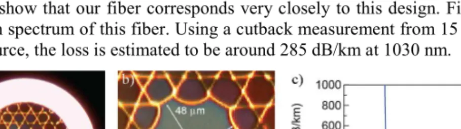
The Kagome-type fiber used in our experiment consists of a 7-cell, 3-ring hypocycloid-core Kagome-cladding HC-PCF designed for operation at 1030 nm. Figures 1(a) and 1(b) show near field images of this fiber. The fiber hypocycloid-shaped core has a diameter of 41 μm for the inner circumscribing circle and 48 μm for the outer one. The pitch is 13 μm, and the fiber outer diameter is 175 μm. A maximum coupling efficiency of 86% was achieved for an optimized input beam diameter of 30 µm. The ideal fiber design has a perfect 6-folded symmetry without any distortion in the core structure to avoid detrimental effects. Figures 1(a) and 1(b) show that our fiber corresponds very closely to this design. Figure 1(c) shows the attenuation spectrum of this fiber. Using a cutback measurement from 15 m to 5 m with a white light source, the loss is estimated to be around 285 dB/km at 1030 nm.
Fig. 1. 7-cell 3-ring hypocycloid-core Kagome-cladding HC-PCF used in our experiments: (a) image of the whole fiber (b) zoom on the hypocycloid-shaped core with an inner diameter of 41 μm and outer of 48 μm and a pitch of 13 μm, and (c) spectral losses using a cutback measurement from 15 m to 5 m with a white light source.
3. Experimental results
3.1 Setup
The experiments were driven by an Yb:YAG TDL (Fig. 2) similar to the laser described in [32]. It consists of a SESAM-modelocked TDL based on Yb:YAG delivering up to 8 W of average power at 3.91 MHz, with pulse durations of 860 fs, as shown in Figs. 2(b) and 2(c). Out of the 8 W output power, 7.3 W of average power were available to launch into the HC-PCF, corresponding to pulses of 1.95 μJ.
Fig. 2. Thin-Disk Laser (TDL) set-up: (a) laser cavity: 38-m long cavity (b) spectrum of the laser measured with an OSA corresponding to a 1.36 nm sech2 spectrum (c) autocorrelation
trace of the laser based on second-harmonic generation (SHG) measurement with 860 fs sech2
The experimental set-up for both beam delivery and pulse compression experiments is presented in Fig. 3. The output of the laser is launched into the Kagome fiber with a set of lenses to ensure optimal mode matching to the fundamental mode of the fiber. The theoretical coupling efficiency for Kagome fibers is 94%, corresponding to the overlap between a TEM00
mode and the fundamental mode guided by the fiber (HE11). From transmission
measurements done over different fiber lengths with the laser presented in Fig. 2, we estimate our coupling efficiency to be 86% and the losses in the fiber at 1030 nm to be 283 dB/km.
A gas chamber was placed on the back of the fiber using the same sealing technique as the one described in reference [26]. With this chamber, gases can be injected into the fiber with adjustable pressure, and a constant gradient of pressure in the fiber can be achieved [33]. The input face was left open in order to avoid stress on the fiber structure, which could result in a reduced damage threshold [23,26]. The fiber was coiled with a radius of approximately 50 cm. To ensure the quality of the output beam and its linear polarization, we used a polarization beam splitter (PBS) with 20 dB of extinction ratio. This main polarization has been selected to maximize the transmitted power through the PBS by adjusting the polarization of the beam before and after the HC-PCF.
Fig. 3. Set-up of the experiment: The input laser beam is coupled into the 2.8-m fiber, which is coiled with a radius of 50 cm. A gas chamber is placed on its end, while the input facet is exposed to ambient air. The output beam was sent through a half-wave plate and a polarizing beam splitter.
3.2 Beam delivery of multi-MW peak power pulses
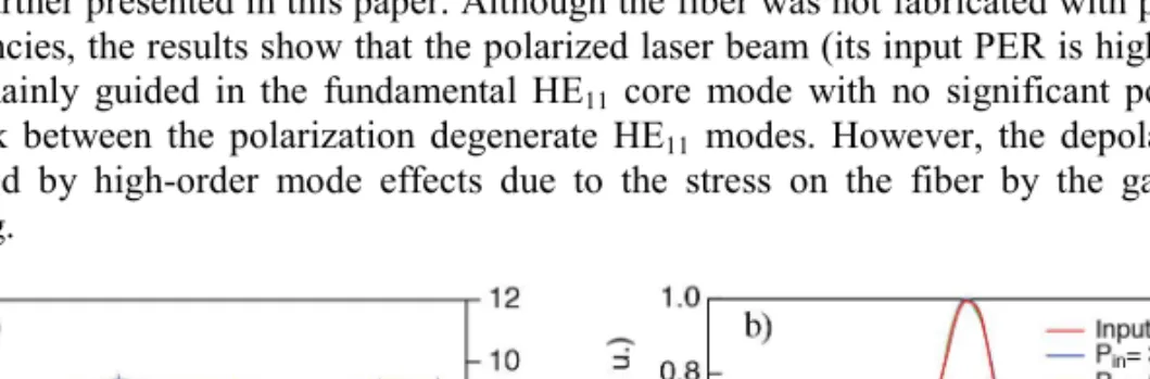
We first evaluate the transmission properties of the 2.8-m fiber in air, for which the coupling and input polarization were optimized to maximize the transmission and the output polarization extinction ratio (PER). As shown in Fig. 4(a), we achieved 71% of average transmission for a PER of 9 dB. This result corresponds to a polarized transmission of 63% over 2.8 m of fiber for the main polarization. This polarized output will correspond to all results further presented in this paper. Although the fiber was not fabricated with polarization dependencies, the results show that the polarized laser beam (its input PER is higher than 20 dB) is mainly guided in the fundamental HE11 core mode with no significant
polarization-cross-talk between the polarization degenerate HE11 modes. However, the depolarization is
dominated by high-order mode effects due to the stress on the fiber by the gas chamber mounting.
Fig. 4. Transmission properties of Kagome Type HC-PCF in air: (a) Transmission and corresponding PER for different input average powers (b) Output spectrum of the system through a Polarizing Beam Splitter (PBS) for different input average powers.
In Fig. 4(b), we show a measurement of the output spectrum of the main polarization for several input powers. In this case, no significant amount of self-phase modulation (SPM) was detected even at maximum power. This result confirms that the overlap between the transmitted mode and the surrounding silica structure is very low. The small amount of spectral broadening shown in Fig. 4(b) is consistent with SPM due to the atmospheric air inside the fiber.
We measured the beam quality of the main polarization to be M2 < 1.15, as shown in Fig.
5. A focusing lens with a focal length of 80 mm was placed after the PBS. For an automated M2 characterization we used a two-axis scanning slit optical beam profiler (BP109-IR from
Thorlabs). The measured M2 in both transverse directions is independent of the input power
(red and blue curves), indicating that the high powers are not distorting the modal properties of the fiber or coupling light into higher order spatial modes.
Fig. 5. M2 measurement of the polarized output using the 2.8-m long fiber in air: (a) At low
input power: 0.1 W (b) At high input power: 6.9 W.
3.3. Pulse compression with xenon filled HC-PCF
Pulse compression in hollow-core fibers relies on SPM generated by the nonlinearity of gases. As shown in Fig. 4(b), no significant spectral broadening was observed in air with up to 1.9 MW peak power. In order to increase the nonlinearity for pulse compression, we used Xenon, a single-atom gas with a significantly higher nonlinear refractive index than air (for Xenon, n2
= 8.1 10−23 m2/W/bar at 800 nm [34]; for air, n
2 = 2.9 10−23 m2/W/bar at 800 nm [34]). Figure
6(a) shows the spectral broadening occurring on the main polarization of the output of the fiber when 16 bar of Xenon are applied on the chamber. In this case the output power after the PBS was 4.8 W, corresponding to a polarized transmission of 63%. The bandwidth of the output spectrum is 58 nm broad (FWHM), which was guided without significant distortions.
Fig. 6. Optical spectrum: (a) Measured spectrum for input and output spectrum using the 2.8-m long Xe-filled Kagome fiber which shows a spectral broadening from the 1.36 nm FWHM sech2 input spectrum (red) of the 860-fs input pulses to 58 nm FWHM (blue) (b) The
Using a split-step Fourier-transform algorithm, we obtained a very good agreement with the measurements (Fig. 6(b)). An extra peak is present in the output spectrum compared to the simulation. This extra contribution is most likely due to the propagation of remaining higher-order mode, which experiences lower SPM than the fundamental mode. For these simulations, we used a fixed fiber length of 2.8 m. The Zero Dispersion Wavelength (ZDW) of the fiber was close to our operating wavelength of 1030 nm [27]. The pressure of Xenon has also an effect on the dispersion of the fiber [35], which is estimated to add a group velocity dispersion (GVD) in the range of ±0.1 ps2/km over the full span of pressure present
in the fiber. The dependence of the dispersion with the pressure was taken into account. The measured input mode diameter for maximum coupling efficiency is 30 µm. We use the mode field diameter (MDF) as the only free parameter in our simulation and obtained good agreement for an assumed value of 28.5 µm. The slight disagreement of 5% might be caused by the dispersion of the nonlinear refractive index of Xenon, since we used values measured at 800 nm. We did not include any Raman effects since single atom gases such as Xenon do not show a Raman response [34]. Furthermore, we included losses of 283 dB/km and the coupling efficiency of 86% for this fiber. In our simulations, we used a linear dependence between the non-linear refractive index of the gas and the pressure [34]. We modeled the pressure profile along the length of the fiber with Hagen-Poiseuille fluid dynamics, assuming a compressible gas and a low flow velocity. This approach results in the following steady-state pressure profile [33]:
2 2 2 0 0 ( ) ( L ) x p x p p p L = + − × (1)
where p0 and pL are the pressure at the input and output ends of the fiber, respectively, x is the
position along the fiber, and L is the total length of the fiber. We estimated values for p0 and
pL to be 1 bar and 16 bar.
We compressed the pulses using a single-pass grating compressor [36] with two diffractive gratings of 1250 lines/mm in transmission. The distance between the gratings was around 0.3 mm for an incident angle of 41°, which results in a group delay dispersion (GDD) in the order of −6x10³ fs2. The residual spatial chirp was not significant. The power
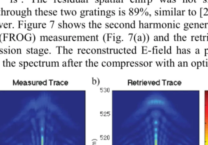
transmission efficiency through these two gratings is 89%, similar to [26], leading to 4.2 W of compressed average power. Figure 7 shows the second harmonic generation (SHG) frequency resolved optical gating (FROG) measurement (Fig. 7(a)) and the retrieval (Fig. 7(b)) of the pulses after the compression stage. The reconstructed E-field has a pulse duration of 48 fs (FWHM). We measured the spectrum after the compressor with an optical spectrum analyzer
Fig. 7. SHG FROG characterization of the compressed pulses at the maximum compressed power of 4.2 W: (a) measured trace (b) retrieved trace. The FROG grid used was 256x256.
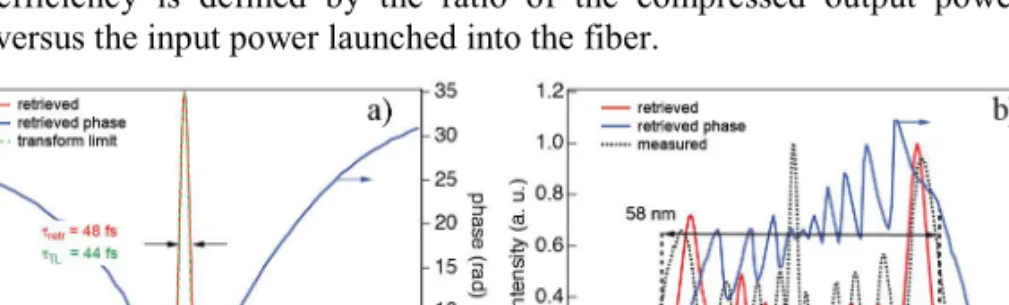
(OSA) independent of the FROG measurement, showing a good agreement with the spectrum retrieved by the FROG algorithm (Fig. 8(b)). The calculated Fourier transform of this OSA-measured spectrum would allow for a transform-limited pulse duration of 44 fs (Fig. 8(a), green curve), whereas the retrieved pulse has a FWHM of 48 fs (Fig. 8(a), red curve). The main compressed peak contains around 50% of the total pulse energy. In fact, our single-pass grating compressor was optimized with a compression factor of 18, reducing the 860-fs input pulse duration to 48 fs. The pulse energy was 1.1 µJ, corresponding to a peak power of 10 MW taking into account the more complex temporal profile retrieved from the FROG measurement. The overall power efficiency into the polarized pulse-compressed output is 56%. This efficiency is defined by the ratio of the compressed output power after the compressor versus the input power launched into the fiber.
Fig. 8. Pulse characterization of the compressed output: (a) intensity of the retrieved pulse with its phase and transformed limited pulse in the time domain. The compressed pulse exceeds 10 MW of peak power with sub-50 fs. (b) Retrieved spectrum of the compressed output with its phase and measured spectrum.
4. Further scaling of this approach: self-focusing considerations
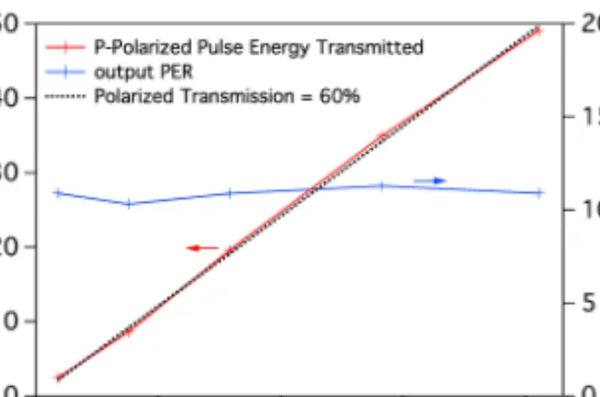
As mentioned in section 1, there is a need for efficient compression schemes of high power sub-picosecond systems operating in the 1-µm wavelength range. The thin disk laser system we used for these measurements was limited to a pulse energy of less than 2 µJ. In order to access higher energies, we performed preliminary transmission experiments with a high-energy picosecond amplifier system. We used a commercial MOPA laser system (Duetto from Time-Bandwidth Products), which delivers high pulse energy with high average power in 10.5 ps-long pulses (FWHM < 0.2 nm) at 1064 nm. The repetition rate is adjustable from 50 kHz to 8 MHz at nearly constant output power (leading to pulse energies of up to 200 µJ). In these initial experiments, we used a relatively long distance between the laser output and the fiber input coupling, which was put onto an additional breadboard, due to the limited space available around the seed laser. The 10-cm long air-filled Kagome fiber could withstand up to 116 µJ and 10 MW of peak power at 50 kHz with an average power of 6 W before damage occurred on its input facet. With a transmission of 83%, it corresponds to a transmitted peak power of more than 8 MW. For a longer fiber length, we replaced the air inside the fiber with helium to suppress spectral broadening [25]. For the 2.8-m long fiber filled with helium, input pulse energies of up of 80 µJ were possible before the onset of damage to the fiber in its middle section when an unexpected helium pressure change occurred. The polarized transmission was of 60% in this case as shown in Fig. 9, resulting in around 4 MW of transmitted pulse peak power.
These preliminary results show that energetic pulses with 8 MW of peak power can be transmitted in such fibers. Solid-core silica fibers already experience self-focusing for peak power close to 4 MW [37]. Because of the non-optimal launching setup for these preliminary studies, we cannot yet make a quantitative prediction of the maximum input energies. We expect that the current setup was limited by imperfect mode matching and launching instabilities. We expect that better launching conditions (possibly in combination with a mode cleaner [38]) will enable substantially higher pulse energies.
Fig. 9. Transmission and polarization extinction ratio (PER) after a 2.8-m long fiber. The Kagome fiber was filled with helium and the input pulse energy was launched at a 50 kHz pulse repetition rate and with an input pulse duration of 10.5 ps from a commercial MOPA laser system (Duetto from Time-Bandwidth Products).
At one point self-focusing may become significant even in gas-filled Kagome fibers, but we believe that this will not be the dominant damage mechanism in HC-PCFs. The theory of self-focusing in bulk media and hollow waveguides have been well described in [39,40] showing the limitations of each technique without taking into account thermal issues that will become an additional limitation with higher average power. Kerr nonlinearities can lead to a transfer of energy to high order spatial modes. However, the peak powers for this process are substantially larger, and the typical peak powers are well above the GW regime for noble gases. Given that current HC-PCFs have substantially smaller mode areas than hollow-core capillaries, HC-PCFs will thus not be limited by self-focusing. Instead, other nonlinear effects such as ionization [41], four-wave mixing, and supercontinuum generation would occur at much lower peak powers [31].
5. Conclusion
This study confirms the potential of Kagome-type HC-PCF for beam delivery and pulse compression of multi-MW peak power pulses at high average power as predicted in [26].
We used a SESAM mode-locked thin disk laser operating at 1030 nm with a pulse repetition rate of 3.9 MHz and a pulse duration of 860 fs. With this laser, the following maximum input parameters were available for our pulse compression experiments: 7.9 W average power, 1.9 µJ pulse energy, 1.9 MW of peak power. Spectral broadening into Kagome-type HC-PCFs filled with Xenon supported sub-50 fs pulses at an average power of 4.2 W after a single-pass grating compressor with a pulse energy of 1.1 µJ and a peak power of 10 MW. Furthermore the compressed pulses had a good beam quality and a PER above 20 dB. This result shows that HC-PCF grating compressor systems are very attractive for many furthers applications [10,12].
In addition, we performed initial experiments with even higher >100 µJ pulse energies in the picosecond regime for beam delivery applications. We achieved HC-PCF transmission of picoseconds pulses with energies up to 97 µJ at a center wavelength of 1064 nm in this type of fiber.
Given the results presented in this paper, we believe this technology is ideally suited for simple and efficient compression of state-of-the art thin disk lasers which currently achieve up to 41 µJ pulse energy [9] and 275 W of average power [8]. We expect to achieve more than 100 MW compressed pulses from such sources in the future.
Acknowledgments
We would like to acknowledge financial support by the Swiss National Science Foundation (SNF), Agence National de Recherche (ANR), and Engineering and Physical Sciences Research Council (EPSRC).