HAL Id: cea-02886853
https://hal-cea.archives-ouvertes.fr/cea-02886853
Submitted on 1 Jul 2020
HAL is a multi-disciplinary open access
archive for the deposit and dissemination of
sci-entific research documents, whether they are
pub-lished or not. The documents may come from
teaching and research institutions in France or
abroad, or from public or private research centers.
L’archive ouverte pluridisciplinaire HAL, est
destinée au dépôt et à la diffusion de documents
scientifiques de niveau recherche, publiés ou non,
émanant des établissements d’enseignement et de
recherche français ou étrangers, des laboratoires
publics ou privés.
Metallic Mg insertion in rf deposited MgO barrier
M. M. C. Souzaa, R. C. Sousa, C. Ducruet, S. Auffret, B. Dieny
To cite this version:
M. M. C. Souzaa, R. C. Sousa, C. Ducruet, S. Auffret, B. Dieny. Metallic Mg insertion in rf deposited
MgO barrier. Journal of Applied Physics, American Institute of Physics, 2010, 107, pp.09C702.
�10.1063/1.3355995�. �cea-02886853�
J. Appl. Phys. 107, 09C702 (2010); https://doi.org/10.1063/1.3355995 107, 09C702
© 2010 American Institute of Physics.
Metallic Mg insertion in rf deposited MgO
barrier
Cite as: J. Appl. Phys. 107, 09C702 (2010); https://doi.org/10.1063/1.3355995
Submitted: 03 November 2009 . Accepted: 05 December 2009 . Published Online: 20 April 2010 M. M. C. Souza, R. C. Sousa, C. Ducruet, S. Auffret, and B. Dieny
ARTICLES YOU MAY BE INTERESTED IN
Tunnel magnetoresistance of 604% at by suppression of Ta diffusion in pseudo-spin-valves annealed at high temperature
Applied Physics Letters 93, 082508 (2008); https://doi.org/10.1063/1.2976435
230% room-temperature magnetoresistance in magnetic tunnel junctions
Applied Physics Letters 86, 092502 (2005); https://doi.org/10.1063/1.1871344
Perpendicular-anisotropy CoFeB-MgO magnetic tunnel junctions with a MgO/CoFeB/Ta/ CoFeB/MgO recording structure
Metallic Mg insertion in rf deposited MgO barrier
M. M. C. Souza,a兲R. C. Sousa, C. Ducruet, S. Auffret, and B. Dieny
SPINTEC (UMR 8191 CEA-CNRS-UJF), CEA/INAC, 38054 Grenoble Cedex, France
共Presented 21 January 2010; received 3 November 2009; accepted 5 December 2009; published online 20 April 2010兲
Metallic Mg insertions in rf deposited MgO barrier of magnetic tunnel junctions structures were investigated in a resistance-area 共RA兲 range from 1 to 1000 ⍀m2. For the first time,
investigations on Mg insertions above the MgO barrier and simultaneously on both sides of the barrier are reported. It is shown that for RA larger than 5 ⍀m2, a bottom Mg insertion does not
improve the tunnel magnetoresistance 共TMR兲 ratio compared to a sample with no Mg insertion. Furthermore, a top Mg insertion yields a lower TMR ratio decreasing as the Mg thickness is increased. On the other side, for RA lower than 5 ⍀m2, there is no significant difference between
top and bottom Mg insertions indicating that in this region, the MgO crystallization occurs mainly during the annealing process. In the RA range investigated, there is no significant difference in coupling field for different insertions. In very low RA regions between 1 and 10 ⍀m2, an increase
in TMR is observed for 0.3 nm insertions simultaneously below an above the barrier. © 2010
American Institute of Physics.关doi:10.1063/1.3355995兴 I. INTRODUCTION
Magnetic tunnel junctions 共MTJ兲 are the core elements of magnetic random access memories共MRAM兲 and consid-ered for other spintronic devices because of their tunable resistance range and large magnetoresistance amplitude. Studies on MgO barriers have been encouraged since the publication of a series of theoretical calculations that pre-dicted an extremely high TMR above 1000% in MTJ with crystalline MgO barrier.1,2The use of such barriers in tunnel junction devices for magnetic read heads which have resis-tances of about 50 ⍀ requires target values of resistance-area共RA兲 product below 1 ⍀m2. Besides, in spin transfer torque MRAM, there is a need to reduce RA level below 10 ⍀m2to reduce the write voltage well below the barrier breakdown voltage. Recently, several results demonstrated that the insertion of a thin Mg layer deposited on the bottom ferromagnetic electrode prior to the MgO barrier deposition enhances the TMR signal in the low RA value range.3,4The Mg insertion also allows decreasing the RA product by re-ducing the barrier height or the effective thickness of the MgO barrier. Some studies concluded that this improvement is due to the reduction of initially oxidized interface, while others claimed that it is due to the improvement in the MgO texture. Up to now the physical influence of Mg insertion on RA and TMR amplitude is not yet clear. This work further investigates the effect of metallic Mg insertion below and above MgO barriers, and simultaneously on both sides of the barrier. The TMR signal dependence on the metallic Mg thickness was studied in the RA range from 1 to 1000 ⍀m2.
II. EXPERIMENTS
The magnetic stack consists of seed layer/Ta 3/CoFeB 4/Mg insert/MgOx/Mg insert/CoFeB 3/Ru 1.8/Co 2/IrMn
7/capping layer共thickness in nanometers兲. The Mg insertion thickness was varied between 0 and 0.5 nm for the top and bottom insertions. The free layer consists in CoFeB and pinned layer is a synthetic antiferromagnet exchanged biased by an IrMn layer. The seed and capping layers are Ta 3/CuN 60/Ta 5/Ru 7 and Ta 5/Ru 7, respectively. The magnetic stack was deposited on a 100 mm diameter thermally oxidized Si wafer. The metallic layers were prepared by dc sputtering at an Ar pressure of 2.3⫻10−3 mbar and room temperature. The MgO barrier was deposited by rf sputtering from an MgO target in an off-axis configuration. With this wafer-target configuration, a MgO thickness gradient is obtained. The MgO wedge thickness is calculated from the Kiessig fringes measured by x-ray diffraction. Using this off-axis deposition 共wafer center offset by 100 mm from the target center兲, a MgO wedge varying from 0.7 to 1.8 nm across the wafer is obtained for our given deposition time. For the same deposition time, when the substrate is facing the target, the corresponding MgO thickness is 2.2 nm. Profile calibration measurements show that this offset condition produces a quasilinear thickness profile across the wafer. Very similar profile was also observed for others materials共Mg and Al兲 in our deposition tool. The annealing temperature was opti-mized in a range from 270 to 370 ° C, with the highest TMR ratio being obtained at about 340 ° C. The samples were sub-sequently annealed under vacuum at 340 ° C for 2 h under a magnetic field of 2.3 kOe at low 10−5 mbar base pressure. The TMR ratio and the RA product were obtained from a current-in-plane共CIP兲 measurement on unpatterned wafers.5 Magnetic characterizations were made using a vibrating sample magnetometer共VSM兲.
III. RESULTS
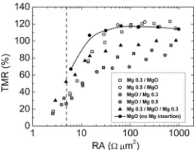
TMR ratio is plotted as a function of RA product in Fig.
1. In this graph, we can define two distinct regions: RA larger than 5 ⍀m2 and smaller than this value. For RA a兲Author to whom correspondence should be addressed. Electronic mail:
JOURNAL OF APPLIED PHYSICS 107, 09C702共2010兲
values larger than 5 ⍀m2, the Mg insertion below or above the MgO barrier does not improve the TMR ratio com-pared to the sample without Mg insertion. This is similar to what had been previously observed for bottom Mg inser-tions. Comparing the two types of insertions, we observed that the top insertion results in a lower TMR value compared to the bottom insertion and no-insertion samples. At high RA values, TMR signal drops as the Mg is increased from 0.3 to 0.5 nm. In RA region lower than 5 ⍀m2, no significant
difference in TMR is observed between top and bottom in-sertions. The reason which has been put forward to explain the increase in TMR observed at low RA levels in bottom metallic Mg insertions is an improvement in the MgO共001兲 crystal orientation upon annealing. It is striking that the same effect seems to occur when the Mg insertion is introduced after the MgO barrier deposition. This is due to the fact that the crystallization of MgO and CoFeB mainly occurs during the annealing process. As a result, the positioning of the Mg insertion above or below the MgO barrier does not matter so much since in both cases the Mg insertion at the MgO/ CoFeB interface equivalently affects the CoFeB and MgO crystallization. Improvements from the Mg insertions are es-pecially clear in the RA product region below 10 ⍀m2, which is also the most relevant for applications requiring large current density. In this region, TMR and RA levels for a no-insertion sample could not be evaluated since no CIP measurement was possible because the free and pinned lay-ers become increasingly coupled. Therefore RA values below 5 ⍀m2can only be obtained by introducing an Mg
inser-tion. Since the effect is most noticeable in the very thin bar-rier range, improved tunnel barbar-rier continuity and pinhole suppression might also be playing a role in the observed TMR improvement. The highest TMR signal observed for RA values between 1 and 10 ⍀m2 was obtained in
samples having simultaneously 0.3 nm Mg insertions below and above the MgO barrier, showing 50% TMR and an RA of about 4.8 ⍀m2. High-resolution TEM images are being
carried out to compare the barrier quality and conformity in the low RA range.
The RA product is plotted in Fig.2 as a function of the MgO thickness for different 0.3 nm Mg insertions. The RA increases exponentially as a function of the barrier thickness as expected from tunneling. For RA levels below 10 ⍀m2,
experimental points slightly deviate from the exponential be-havior for both bottom and top Mg insertions. This can be explained assuming an increase in the barrier pinhole density
in the barrier, resulting in an increasing fraction of metallic conduction as opposed to the electron tunneling through the barrier.
At same nominal thickness of MgO, a bottom insertion presents an RA level lower compared to a no-insertion sample while a top insertion shows a RA level greater than the sample without Mg. In order to explain this fact, let us consider the schematic from Fig.3. Near the interface, some of the oxygen from the MgO layer migrates to the Mg layer. The region of oxygen diffusion contains lot of oxygen va-cancies and is poorly insulating. Consequently, we can con-sider in first approximation that two different kinds of MgO coexist:共i兲 one from our target noted MgO, close to stochio-metric and characterized by a relatively high barrier height ⌽1 and共ii兲 another created from oxygen diffusion from the
first type of MgO to the Mg layer noted MgOxwith a lower
barrier height⌽2. If t1 and t2 are the respective thickness of
these two oxides then, we have tMgO+ 0.3 nm= t1+ t2. For a
top insertion, this mechanism of oxygen migration is similar. As predicted from Schrödinger equation, the RA product de-pends exponentially on the barrier thickness t and the barrier potential height⌽
RA⬀ exp
冋
4t冑
2m冑
⌽h
册
, 共1兲where h denotes Planck constant and m the electron effective mass. Considering the two types of oxide, we can write:
RA⬀ exp
冋
4冑
2m冑
⌽1共tMgO+ 0.3 − t2兲h
册
⫻ exp
冋
4冑
2m冑
⌽2t2h
册
. 共2兲When varying the nominal MgO thickness, we suppose that
t2is not modified. Thus, the ln共RA兲 versus tMgOcurve has a
slope of 4共2m⌽1兲1/2/h and a shift in x-direction given by FIG. 1. Dependence of the TMR ratio on the RA product for different Mg
insertions. The behavior of samples is analyzed in two different regions defined by the dashed line: RA smaller and greater than 5 ⍀m2.
FIG. 2. RA product as a function of the as deposited MgO thickness for different 0.3 Mg insertions.
FIG. 3. Schematic of oxygen migration from MgO layer to Mg layer in a bottom insertion.
4
冑
2m冑
⌽10.3h +
4
冑
2m共冑
⌽2−冑
⌽1兲t2h . 共3兲
The first term in this expression is positive while the second one is negative since⌽1⬎⌽2. Considering that the potential
height⌽1 is not modified, the shift can be positive or
nega-tive depending on the potential height ⌽2 and the thickness t2. By assuming that the mechanisms of oxygen migration to
the Mg layer for top and bottom insertion are different, the potential heights in these two configurations are probably different as well as the thickness of the resulting MgOxlayer.
This can explain the different shifts in our curves. The slope is about twice larger compared to other measurements in rf deposited MgO.3 It is probably due to crystalline defects in our barrier disfavoring the penetration of electrons with ⌬1 symmetry in the barrier. This is consistent with the lower TMR of these samples compared to the literature.
The magnetic hysteresis loop of the free layer was mea-sured by VSM. The loops are slightly shifted from zero field because of the coupling between free layer and pinned layer. This coupling is due to pinholes or orange peel coupling. In the case of direct pinhole coupling, there is an associated decrease in the TMR since the two electrodes cannot be aligned antiparallel. The barrier continuity can be inferred from the free layer coupling field. The coupling field is plot-ted in Fig.4as a function of the MgO thickness for samples with and without Mg insertions. The coupling changes from antiferromagnetic 共positive values兲 to ferromagnetic as the
MgO thickness decreases. The inset shows that above a criti-cal thickness, the magnitude of the coupling remains below ⫺4 Oe. For thickness lower than this critical value, the free and pinned layers become increasingly coupled. These criti-cal thicknesses correspond to 1.25, 1.36, and 1.12 nm for MgO with no insertion, with a bottom insertion and a top insertion, respectively. The RA measured by TMR CIP mea-surements for these critical thicknesses are, respectively, 14.6 ⍀m2, 13.7 ⍀m2, and 10.6 ⍀m2. It is interest-ing to note that these values are remarkably close.
IV. CONCLUSION
MgO tunnel barriers were investigated with top and bot-tom metallic Mg insertions in the RA range from 1 to 1000 ⍀m2. For RA levels larger than 5 ⍀m2, the same level of TMR was obtained for the samples with bottom Mg insertion and without Mg insertion. In this region, top Mg insertion samples show lower TMR values decreasing as the metallic Mg is increased. For RA lower than 5 ⍀m2, the
TMR is improved and no significant difference is observed on the TMR depending on the location of the Mg insertion above or below the barrier. In the low RA region, the highest TMR of 50% at 4.8 ⍀m2 was obtained for simultaneous
0.3 nm thick Mg insertions below and above the MgO bar-rier.
ACKNOWLEDGMENTS
This work was partially funded by the ANR-07-NANO-052-02 project. M. M. C. Souza acknowledges a PhD schol-arship funding by Cluster Recherche Micro-Nano and the Rhone-Alpes region.
1W. H. Butler, X.-G. Zhang, and T. C. Schulthess,Phys. Rev. B63, 054416 共2001兲.
2J. Mathon and A. Umerski,Phys. Rev. B63, 220403共R兲 共2001兲. 3K. Tsunekawa, D.-D. Djayaprawira, M. Nagai, H. Maehara, S. Yamagata,
N. Watanabe, S. Yuasa, Y. Suzuki, and K. Ando, Appl. Phys. Lett.87,
072503共2005兲.
4Y. Lu, C. Deranlot, A. Vaurès, F. Petroff, J.-M. George, Y. Zheng, and D. Demailles,Appl. Phys. Lett.91, 222504共2007兲.
5D. C. Worledge and P. L. Trouilloud,Appl. Phys. Lett.83, 84共2003兲. FIG. 4. Coupling field of the free layer plotted as a function of the nominal
MgO thickness.