HAL Id: hal-03189146
https://hal.archives-ouvertes.fr/hal-03189146
Submitted on 2 Apr 2021
HAL is a multi-disciplinary open access
archive for the deposit and dissemination of
sci-entific research documents, whether they are
pub-lished or not. The documents may come from
teaching and research institutions in France or
abroad, or from public or private research centers.
L’archive ouverte pluridisciplinaire HAL, est
destinée au dépôt et à la diffusion de documents
scientifiques de niveau recherche, publiés ou non,
émanant des établissements d’enseignement et de
recherche français ou étrangers, des laboratoires
publics ou privés.
Copyright
Indoor Experimental Evaluation of Ultra-wideband
MU-MISO TRDMA
Ali Mokh, Ramin Khayatzadeh, Julien de Rosny, Mohamed Kamoun,
Abdelwaheb Ourir, Arnaud Tourin, Mathias Fink
To cite this version:
Ali Mokh, Ramin Khayatzadeh, Julien de Rosny, Mohamed Kamoun, Abdelwaheb Ourir, et al.. Indoor
Experimental Evaluation of Ultra-wideband MU-MISO TRDMA. VTC spring 2021, IEEE, Apr 2021,
Helsinki, Finland. �hal-03189146�
Indoor Experimental Evaluation of Ultra-wideband
MU-MISO TRDMA
Ali Mokh
1, Ramin Khayatzadeh
2, Julien de Rosny
1, Mohamed Kamoun
2, Abdelwaheb Ourir
1, and Arnaud Tourin
Mathias Fink
11
ESPCI Paris, PSL Research University, CNRS, Institut Langevin, 1 rue Jussieu, F-75005 Paris, France
2Mathematical and Algorithmic Science Lab, France Research Center, Huawei Technologies Co.,Ltd.
Abstract—MISO Time-Reversal (TR) communication marks a paradigm shift for ultrawideband (UWB) communications because the processing is mainly carried out by the transmitter, which is ideal for some applications. Thanks to its focusing property, TR is naturally dedicated to multiple access trans-mission (TRDMA). Previous research works have focused on the theoretical performance of TRDMA. In this paper, Multi-user MISO (MU-MISO) TRDMA transmission is evaluated experimentally for the first time to the best of our knowledge, and by simulations. An experimental setup is used to measure the TRDMA signals for different bandwidth in multi-user scenario. The experimental results are then used in a simulation to evaluate the bit error rate and the performance of the system.
Index Terms—Time-Reversal, Multi-user MISO (MU-MISO), TRDMA, Wave focusing, Beamforming.
I. INTRODUCTION
A Time reversal mirror is an apparatus to focus wave both in time and in space. It is based on the time-reversal symmetry of propagating media. Thirty years ago, it has been first applied to focus ultrasonic waves in water, tissues, solids. Time Reversal mirror is very efficient in complex media such as multiple scattering media [1] or cavities [2] because it takes benefit of the reflections to enhance the focusing. In acoustics, the main application of time reversal is non-destructive control, imaging, therapy [3]. In 2004, the concept of time reversal mirror has been extended to microwave [4] at 2.4GHz. Because the larger the bandwidth, the better the focusing, two years later, a wide-band time reversal was successfully performed [5].
Telecommunication is a natural application field of time reversal mirrors. As soon as the early 2000s, an acoustic time Reversal mirror has been used to transmit bits between two vessels in a shallow water environment near Elba island [6]. Indeed, the temporal pulse compression mitigates the inter-symbol interference (ISI) resulting from multipath propaga-tion, while the spatial focusing reduces inter-user interference (IUI) [7].
Soon after, the interest of time reversal for radio communi-cations appeared. Inside an urban environment, [8] has shown a delay spread reduction of up to a factor of 3. In the case of a mild multipath environment, a good spatial and temporal focusing gain is reached using a transmitter with a sufficiently large number of antenna [9].
Recent research in wireless communications has frequently been focusing on UWB due to its potential in short-range communications and positioning applications thanks to its ability effectively collect energy that is dispersed in rich multipaths [10]. Moreover non-coherent receivers can be used for low-cost and low-power sensors [11], [12], TR is especially suited for UWB Internet-of-Things [13].
In terms of communication theory, TR is a downlink pre-coding technique both for SISO and MU-MISO impulse radio UWB (IR-UWB) wireless communication [14].
A few years ago, TRDMA has been introduced to focus messages to different users (MISO-MU configuration) [15]. TRDMA provides a cost-effective single-carrier alternative with high power efficiency [16], for downlink and uplink transmission [17]. Theoretical analysis for the average signal-to-noise ratio (SNR) of the intended and unintended receivers in a distributed TR transmission scheme was analysed in [18], while a probabilistic analysis (probability density function) of the SNR at the receiver in a TR communication was derived in [19], and then the ergodic capacity and theoretical bit error rate (BER) when phase-shift keying (PSK) modulation is used was also obtained.
For summary, the works in the state of art has focused on the theoretical analysis of TRDMA system. While experimental studies have been performed in a SISO (eg. [20]) or MIMO configuration [21]. However to the best of our knowledge, no experimental study has been performed to test TRDMA in real indoor environments.
In this paper, we evaluated the performance of UWB MISO TRDMA, experimentally and in simulation for indoor transmission for the first time to the best of our knowledge. An experimental setup with an 8 antenna TR base station and 2 single-antenna users is deployed inside a small office. After a channel sounding sequence, the channel is flipped in time and phase conjugated. These signals are sent back by the TR array toward each user and the IUI is probed. These TR focused signals are used to simulate TRDMA communication. The BER is evaluated for different settings.
The rest of the paper is organized as follows. In section II, the principle of TRDMA is restated, and we explain the input-output equations for MISO-TRDMA. In section III, the experimental setup of MISO TRDMA is presented, followed
by the explanation of the channel sounding method. Then the focused signals are shown on each user when estimated chan-nels are time-reversed. Finally, the simulation block diagram and TRDMA simulation results are provided in Section IV.
II. TIMEREVERSALDIVISIONMULTIPLEACCESS
(TRDMA)
This section introduces the model and notations for MU-MISO time reversal (TR) for multi-user scenarios.
A. Time Reversal
Let us consider a MU-MISO transmission system, com-posed of one transmitter equipped with M transmit antennas and N users with single antenna each. We note hi,m[k] the
complex tap at tap time index k of the base-band channel impulse response (CIR) between the m-th transmit antenna and the i-th user. We assume that the CIRs vanishes after L complex taps, i.e, |L[k]| > 0 for 0 k L 1. TR precoding consists in using the flipped and conjugated impulse response (CIR), i.e., gi,m[k] = h⇤i,m[ k], as transmitting filter. In a
MU-MISO scenario, the received signal yj after TR precoding for
user j read, when focusing towards user i is yj[k] =
(x⇤ Rji)[k]
p Rii[0]
+ nj[k]. (1)
where x is the transmit signal, njis an additive white Gaussian
noise with standard deviation , ⇤ is the discrete convolution operator and Rj,ibe the correlation function between the CIRs
of users j and i. This last is given by Rji[k] = [k] M X m=1 L 1X l=0 h⇤i,m[l]hj,m[l] + M X m=1 L 1X l=0 L 1X p=0,p6=l h⇤i,m[l]hj,m[p] [k (p l)] | {z } ISI,IUI . (2)
Note that the correlation function is a time symmetric function, i.e., Rii[ k] = Rii⇤[k]. At k = 0, the correlation function is
maximum and real. With multi-path channels, when applying TR precoding with the CIR of user i, the time-reversed field focuses in time and in space (in user i location) [22] with a peak given by the auto-correlation function Ri,i[0]. Indeed
at this time and location, M ⇥ L signals add coherently. This coherent combination is corrupted by random interference that generate ISI (k 6= 0) and IUI (i 6= j).
III. MISO TRDMA EXPERIMENTSETUP ANDRESULT
A. Experiment Setup
To evaluate the MISO-TRDMA scheme, we use an experi-mental setup to sound the channel and time reverse the signals (see figure 1). It is composed of a transmitter array with M = 8 antennas, all connected to a solid-state RF switch. The input of the 1x8 switch is connected to an RF amplifier that is fed by an Arbitrary Waveform Generator (AWG) from Tektronix (AWG-7012). This last is used to generate the signal
Fig. 1. MISO TRDMA Experimental Setup
to transmit. At the receiver side, two antennas (N = 2) are connected to two low noise amplifiers and then to 2 inputs of an RF oscilloscope (Tektronix TDS6604B). The AWG and the oscilloscope are connected to an ethernet network switch and controlled by a computer. The AWG triggers the oscilloscope to ensure synchronization. The sampling rate of the oscilloscope and the generators are 12.5 and 10 GHz, respectively. The experiment is performed inside a small office room, 3m x 3m in dimension, where the multi-path occurs. B. Channel Estimation And Time Reversal
Channel estimation and time reversal are mainly done in 3 steps. First, a chirp signal c(t) with carrier frequency of fc = 2GHz and bandwidth of B is emitted through the
channel using an RF switch and 8 TX antennas. The received RF signals are sampled using the digital oscilloscope and recorded into the computer. The 8x2 CIR is estimated by correlating the 8x2 received signals with c(t). Note that the emission and the reception are directly performed in the RF band. The CIR is flipped in time and resampled to change the sampling frequency from 12.5 GHz to 10 GHz. Each TR CIR is then sent back from the corresponding TX antenna, i.e., for instance, the CIR recorded between the 3rd Tx antenna and the second Rx antenna, is sent back by the 3rd Tx antenna. At the end, the TR signals are recorded on the 2 Rx antennas and down-converted to store the baseband signals.
C. Results
Since in this experiment we are using a switch between transmit antenna, each signal is transmitted separately. So to emulate MISO TRDMA, we added all received signals from different transmit antennas, when targeting specific receive antenna, and normalized the sum by 1/pM to maintain the same average transmit power.
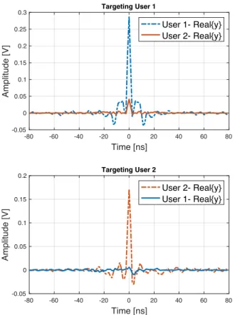
Figure 2 shows the baseband MISO TR received signal at antenna R1 and R2 with 800 MHz bandwidth in multi-user scenario when targeting either antenna R1 or R2. For sake of simplicity, the origin of time in these figures is considered to be at the peak of the time-reversed receive signal (i.e. where
-80 -60 -40 -20 0 20 40 60 80 Time [ns] -0.05 0 0.05 0.1 0.15 0.2 0.25 0.3 Amplitude [V] Targeting User 1 User 1- Real{y} User 2- Real{y} -80 -60 -40 -20 0 20 40 60 80 Time [ns] -0.05 0 0.05 0.1 0.15 0.2 Amplitude [V] Targeting User 2 User 2- Real{y} User 1- Real{y}
Fig. 2. MISO TR received signal and IUI at R1 and R2 when targeting R1 or R2
R[0] is the maximum), so that the autocorrelation function is a pair function as shown in equation (3). Depending on the targeted antenna, we can observe that the focused amplitude is 8 dB and 15 dB higher than on the other antenna. The IUI is due to the imperfect spatial focusing of TR. In the next section, those signals are used in a simulation chain to simulate TRDMA and observe the performance of the proposed system.
IV. TRDMA SIMULATION
A. TRDMA Simulation Scheme
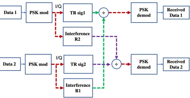
Figure 3 shows the block diagram of the simulated transmis-sion chain of MISO TRDMA based on the measured signals. The binary data for each user are PSK modulated in order to keep the amplitude of the signal fixed, so that we can analyze the effect of the interference on the transmission in different conditions, and the resulting I/Q signals are convoluted with the TR focusing signal. This last can be seen as the time-reversed channel. On each channel, the measured interference is added. At each receiver, the received signal contains the sum of the focused signal and the inter-user interference from the signal transmitted to the other user. This received signal is demodulated with a simple phase detector that estimates the PSK symbol that has the closest phase to the received signal. We counted the error rate by comparing the transmit and detected information.
B. Simulation Results
Let introduce n as the number of taps between the symbols, the symbol rate is then given by B/n and m is the order of PSK modulation. The simulation is run for different order m of PSK modulation. Complex White Gaussian Noise is added to the received signal where the standard deviation is related to the SNR and the amplitude of the central path. Figure 4 represents the BER for the maximum bandwidth, i.e., 800MHz, and at SNR=20 dB for both users. Results show that the smaller the order of modulation or the larger the number of taps between symbols, the smaller the BER. Also, for QPSK modulation, a transmission with BER smaller than 10 4could
be achieved for symbol spacing n = 2, since the effect of ISI becomes negligible. However, because of the IUI, even with large symbol spacing, a minimum BER that is higher than 10 2, respectively higher than 10 2, could not be reduced
for 8-PSK modulation, respectively for 16-PSK modulation, using a simple phase detector. In figure 5, the BER in terms of SNR is plotted. We fixed the symbol spacing at n = 2, and we used different order of modulation (from BPSK to 16-PSK). It is shown that for an SNR less than 20 dB, both BPSK and QPSK could be used with BER less than 10 3, and
an 8-PSK modulation could be implemented with a BER less than 10 3for SNR=30dB. This is suitable for low complexity
devices since no post-processing is needed. But even with such SNR, the 16-PSK modulation still around 10 1, because of the
effect of interference. In figure 6, the effect of the bandwidth on the transmission is evaluated. The BPSK modulation is considered for all simulations, and we measured the BER in terms of number of taps between the symbols for B = 100 MHz, 200 MHz and 400 MHz, only for the first user, and also for SNR=10 dB. The results show that the higher the bandwidth, the more efficient the TR transmission, since the temporal focusing gain increases. Actually, this is reffered to the fact that the higher the bandwidth, the more the system can estimates channel taps during the same symbol duration, and from equation (3), one can see that the grater the number of taps L, the grater the amplitude of the central peak (k=0). Also, by increasing n the BER decreases until it reaches a plateau which is caused by the IUI.
V. CONCLUSION
In this paper, we evaluated experimentally and by a sim-ulation the performance of an UWB MISO TRDMA system for multiuser scenario. Results show that by increasing the time difference between symbols, the effect of the ISI could be reduced, but the IUI still limiting the performance of the system. In addition, the greater the bandwidth is, the more robust the transmission becomes. We can conclude that the TR precoding is suitable in access transmission for multi-user scenario, mainly for low complexity devices in multi-path channel environment as indoor transmission.
REFERENCES
[1] A. Derode, P. Roux, and M. Fink, “Robust acoustic time reversal with high-order multiple scattering,” Phys. Rev. Lett., vol. 75, no. 23, pp. 4206–4209, dec 1995.
Fig. 3. MISO TRDMA simulation chain 1 2 3 4 5 6 7 8 9 10 n 10-5 10-4 10-3 10-2 10-1 100 BER QPSK 8PSK 16-PSK
Fig. 4. BER Vs number of taps (n) of two users for different PSK order of modulation using MISO TRDMA with B=800MHz
[2] C. Draeger and M. Fink, “One-channel time reversal of elastic waves in a chaotic 2d-silicon cavity,” Phys. Rev. Lett., vol. 79, no. 3, pp. 407–410, jul 1997.
[3] M. Fink, “Time-reversed acoustics,” Scientific American, vol. 281, no. 5, pp. 91–97, 1999.
[4] G. Lerosey, J. de Rosny, A. Tourin, A. Derode, G. Montaldo, and M. Fink, “Time reversal of electromagnetic waves and telecommuni-cation,” Phys Rev Lett, vol. 40, no. 19, pp. n/a–n/a, 2005.
[5] G. Lerosey, J. De Rosny, A. Tourin, A. Derode, and M. Fink, “Time reversal of wideband microwaves,” Appl. Phys. Lett., vol. 88, no. 15, p. 154101, 2006.
[6] G. F. Edelmann, T. Akal, W. S. Hodgkiss, S. Kim, W. A. Kuperman, and H. C. Song, “An initial demonstration of underwater acoustic communication using time reversal,” IEEE J. Ocean. Eng., vol. 27, no. 3, pp. 602–609, jul 2002.
[7] C. Oestges, J. Hansen, S. M. Emami, A. D. Kim, G. Papanicolaou, and A. J. Paulraj, “Time reversal techniques for broadband wireless com-munication systems,” in European Microwave Conference (Workshop), 2004, pp. 49–66.
[8] Kyritsi, Papanicolaou, Eggers, and Oprea, “Miso time reversal and
delay-5 10 15 20 25 30 10-4 10-3 10-2 10-1 100 BER BPSK QPSK 8 PSK 16 PSK
Fig. 5. BER Vs SNR of one user for different PSK order of modulation using MISO TRDMA with B=800MHz, with n = 2
spread compression for fwa channels at 5 ghz,” IEEE Antennas Wireless Propag. Lett., vol. 3, no. 1, pp. 96–99, 2004.
[9] S.-Q. Xiao, J. Chen, X.-F. Liu, and B.-Z. Wang, “Spatial focusing characteristics of time reversal uwb pulse transmission with different antenna arrays,” Prog. Electromagn. Res, vol. 2, pp. 223–232, 2008. [10] H. T. Nguyen, J. B. Andersen, and G. F. Pedersen, “The potential use
of time reversal techniques in multiple element antenna systems,” IEEE Commun. Lett., vol. 9, no. 1, pp. 40–42, jan 2005.
[11] B. Wang, Y. Wu, F. Han, Y.-H. Yang, and K. J. R. Liu, “Green wireless communications: A time-reversal paradigm,” IEEE J. Sel. Areas Commun., vol. 29, no. 8, pp. 1698–1710, sep 2011.
[12] Y. Chen, Y.-H. Yang, F. Han, and K. J. R. Liu, “Time-reversal wideband communications,” IEEE Signal Process. Lett., vol. 20, no. 12, pp. 1219– 1222, dec 2013.
[13] Y. Chen, F. Han, Y.-H. Yang, H. Ma, Y. Han, C. Jiang, H.-Q. Lai, D. Claffey, Z. Safar, and K. J. R. Liu, “Time-reversal wireless paradigm for green internet of things: An overview,” IEEE Internet Things J., vol. 1, no. 1, pp. 81–98, feb 2014.
2 4 6 8 10 12 14 16 18 20 n 10-5 10-4 10-3 10-2 10-1 100 BER 100 MHz 200 MHz 400 MHz
Fig. 6. BER Vs number of taps (n) of the first user using TRDMA for different bandwidth
impulse radio uwb communications based on time reversal technique,” Prog. Electromagn. Res, vol. 79, pp. 401–413, 2008.
[15] F. Han, Y.-H. Yang, B. Wang, Y. Wu, and K. J. R. Liu, “Time-reversal division multiple access over multi-path channels,” IEEE Trans. Commun., vol. 60, no. 7, pp. 1953–1965, jul 2012.
[16] M. Lienard, P. Degauque, V. Degardin, and I. Vin, “Focusing gain model of time-reversed signals in dense multipath channels,” IEEE Antennas Wireless Propag. Lett., vol. 11, pp. 1064–1067, 2012.
[17] F. Han and K. J. R. Liu, “A multiuser TRDMA uplink system with 2d parallel interference cancellation,” IEEE Trans. Commun., vol. 62, no. 3, pp. 1011–1022, mar 2014.
[18] L. Wang, R. Li, C. Cao, and G. L. St¨uber, “Snr analysis of time reversal signaling on target and unintended receivers in distributed transmission,” IEEE Trans. Commun., vol. 64, no. 5, pp. 2176–2191, 2016.
[19] W. Lei and L. Yao, “Performance analysis of time reversal communica-tion systems,” IEEE Commun. Lett., vol. 23, no. 4, pp. 680–683, 2019. [20] I. H. Naqvi, G. El Zein, G. Lerosey, J. de Rosny, P. Besnier, A. Tourin, and M. Fink, “Experimental validation of time reversal ultra wide-band communication system for high data rates,” IET Microw. Antennas Propag., vol. 4, no. 5, pp. 643–650, 2010.
[21] H. El-Sallabi, P. Kyritsi, A. Paulraj, and G. Papanicolaou, “Experimental investigation on time reversal precoding for space–time focusing in wireless communications,” IEEE Trans. Instrum. Meas., vol. 59, no. 6, pp. 1537–1543, 2010.
[22] M. Fink, “Chaos and time-reversed acoustics,” Phys. Today, vol. 50, no. 3, pp. 34–40, oct 2001.