Design of an Air Gap Armature for the MIT
Superconducting Generator
by
Maurice-Andre Recanati
B. S., Rensselaer Polytechnic Institute (1992)
SUBMITTED IN PARTIAL FULFILLMENT OF THE REQUIREMENTS FOR THE
DEGREE OF
MASTER OF SCIENCE IN MECHANICAL ENGINEERING
at the
MASSACHUSETTS INSTITUTE OF TECHNOLOGY
May 1st, 1994
© 1994 Maurice-Andre Recanati All rights reserved
The author hereby grants to MIT permission to reproduce and to distribute publicly paper and electronic copies of this thesis document in whole or in part.
Signature of Author:
Research Assistant, Department of Mechanical Engineering
Certified by
/ r. Jseph L. SmiA, Jr.
-rl~b~lsorso
Accepted by:
Dr. Ain Sonin
Chairman, Department Committee
Eng, .
Notice
2
This thesis was prepared as a partial requirement for a Masters Degree in Mechanical Engineering at the Massachusetts Institute of Technology under the
guidance and direct supervision of Professor Joseph L. Smith, Jr.
This report was prepared as an account of work originally sponsored by the United States Government. Neither the author, nor Professor Smith, nor M.I.T. nor its employees makes any warranties, express or implied, or assumes any legal liability or responsibility for the accuracy, completeness, or usefulness of any
information, apparatus, product, or process disclosed, or represents that its use would not infringe privately owned rights. Reference herein to any specific
commercial product, process or service by trade name, mark, manufacturer, or otherwise, does not necessarily constitute or imply its endorsement, recommendation, or favoring by the US Government.
All trademarks herein are the property of their respective owners.
Due to the high risk nature of the project, the writer of this thesis does not assume any financial or legal liability associated with this work.
Design of an Air Gap Armature for the MIT
Superconducting Generator
by Maurice-Andre Recanati
Research Assistant
Submitted in May of 1994 in partial fulfillment of the requirements for the
degree of Masters of Science in Mechanical Engineering.
ABSTRACT
In the United States alone, increasing demand for electricity will create a 20% expansion of the current generating base in the next ten years. International markets will expand even faster, with most of the worldwide
growth coming from natural gas fired combustion turbines and highly efficient combined-cycle plants.'
The MIT Superconducting Generator Program is a high risk, high payoff enterprise which makes use of advanced design concepts and materials in order to offer significant benefits to electrical utilities. Using a rotor which contains a superconducting field winding, a significantly higher magnetic field than that found in conventional generators is created. Due principally to Lens's Law, this intense magnetic field produces a large magnetomotive force (mmf) in the armature winding; hence special considerations must be taken while designing the stator assembly.2
In this thesis, we will begin by explaining in detail the motivations behind this project as well as review and compare the different types of
airgap armature windings developed in industry before introducing the MIT
design.
The core of the thesis is threefold. In the first part, the overall design is derived from basic design specifications and the general layout of the stator is produced. In the second part, various important components such as the
conducting wire, the insulation, the end connectors and the spacers are analyzed and a selection is made based on experimental data. While the first two parts of the thesis have a strong emphasis on design, the third part consists of a basic electrical and thermodynamical analysis of the stator core
A brief section discussing manufacturing, assembly and testing is also
included for possible industrial scale production of the generator before concluding on the feasibility of such a construction.
Thesis Supervisor: Professor Joseph L. Smith, Jr.
Ford Professor of Mechanical Engineering
" Two of the most important duties of an engineer are the design of
engineering systems and the analysis of the behavior or performance of these
systems. [...] A good solution will provide the necessary engineering
information about the situation within the time available for analysis and
with an economy of effort. An analysis which is more complex than necessary
is time consuming and wasteful. "
Joseph L. Smith,
in Engineering Thermodynamics, 1981.
Inspired by Prof. Smith's philosophy, the author of this thesis has endeavored to accomplish the designing as well as the analysis of the superconducting generator armature.
Acknowledgment
This research thesis proved to be quite an interesting and complex endeavor. Despite the slow development of the investigation, mainly due to a
lack of funding and of manpower, I have learned a lot about designing
advanced technology machines. Since my undergraduate degree was in Physics, I had to teach myself in a very short time the basics of design, heat transfer, mechanical and electrical engineering causing an additional, but well spent, delay in the onset of the research.
There were many people who helped me in the course of the research at MIT and to whom I am deeply indebted. I would like to thank Bob
Gertsen, who taught me all that I know about operating a machine shop; Lisa Langone, for her patience, and all the students of the Cryogenics Laboratory
for their support. I would also like to thank Steve Umans and Wayne
Hagman, who each proved to be invaluable assets in the development of the electrical aspect of the stator winding. Prof. James Kirtley, one of the finest professors at MIT, played a central role in my understanding and in my design of the generator. My deepest thanks are extended to Professor Joseph Smith, who patiently supervised my thesis, contributed encouragement and guidance, as well as many insightful ideas and comments.
Finally, I would like to thank the officers and staff of several
corporations for their input and for the use of their facilities throughout my
research. I am also grateful to my friends and especially to my family for
their understanding and moral support.
Thank You
Foreword3
The MIT Superconducting Generator Program, which is conducted
jointly by the Mechanical and Electrical engineering departments, was established in 1967 by professor Joseph Smith. With the support of the Edison Electric Institute, a 45 kVA superconducting synchronous generator utilizing a rotating superconducting field winding was constructed. During the period between 1970 and 1975, EPRI supported the construction of a 3 MVA superconducting generator that was successfully tested as a
synchronous condenser. Using DOE funding, the MIT group subsequently started developing a 10 MVA superconducting generator that would
demonstrate advanced concepts not found in similar generators being designed elsewhere. The construction of the generator and the test facility (consisting of a General Electric LM 1500 turbine and an interconnection to
the Cambridge Electric Company grid), were completed and operational in 1985 after a project stretch-out due to funding restrictions.
In late 1989, support from DOE ceased while EPRI and later DARPA
continued to sustain the testing and modification phases of the generator. Using these DARPA funds, the rotor was modified in 1991 to operate at liquid helium temperature and at 3600 RPM with low vibrations. In the
spring of 1992, EPRI funds were utilized to conduct a series of open circuit tests using a hydraulic spin motor which proved to have inadequate power.
Last summer, the generator was ready to be tested on the local power
grid as a synchronous condenser operating at 13.8 kV at 3600 RPM.
Unfortunately, due to an imperfection in manufacturing, the stator winding
excellent rotor design, the rotor remained superconducting during this sudden transient and no significant losses in the excitation current were detected. Both the rotor and stator structure withstood this transient without any damage or deformations. Further testing of the generator will require a new stator winding since this component is a total loss. This thesis, which is partially funded by EPRI, describes in detail how the new armature is to be constructed when sufficient funds will be appropriated.
Table of Contents
Page
CHAPTER 1: INTRODUCTION
1.1 Motivation of Project 16
1.2 Description of the MIT Rotor 18
1.3 Benefits of Air Gap Armature Design 23
1.4 Types of Air Gap Armature Windings 27
1.5 Introduction to MIT Designs 43
CHAPTER 2: ARMATURE DESIGN
2.1 Design Specifications 45
2.2 Layout Detail 51
2.3 Electrical Specifications 66
2.4 Design Calculations 78
CHAPTER 3: COMPONENT DESIGN
3.1 Selection of the Conductor Bar 95
3.2 Selection of Bar Insulation 117
3.3 Design of the End Connector 129
3.4 Design of the Cooling Spacer 133
3.5 Torque Tube Selection 136
CHAPTER 4: MANUFACTURING and TESTING
4.1 Production Sequence 137
4.2 Manufacturing and Testing of Bars 138
4.3 Assembly and Testing of the Armature 144
CHAPTER 5: THERMODYNAMIC PROPERTIES
5.1 Cooling System Layout 150
5.2 Thermodynamic Analysis 152
5.3 Temperature Profiles 159
5.4 Generator Control 163
CHAPTER 6: ELECTRICAL PROPERTIES
6.1 Circuit Modeling 168
APPENDICES: Appendix A: Appendix B: Appendix C: Appendix D: Appendix E: FOOTNOTES APPENDIX LIST
MIT 10 MVA Helical Armature Specifications
Designing Bars with Smooth Transition Sections
Quantum Mechanical Properties of Copper
Electromagnetic Waves in Conducting Media
Thermal Conduction and Convection in a Fin
10. Page 182 195 199 207 209 214
List of Figures
Page CHAPTER 1
Fig. 1.1 Schematic View of 10-MVA Generator Configuration 19
Fig. 1.2 Cross Section of the 10-MVA Rotor 19
Fig. 1.3 Schematic of Conventional Generator 24
Fig. 1.4 Schematic of Air-Core Synchronous Machine Geometry 24
Fig. 1.5 Topology of Wye and Delta Connected 3-Phase Winding 29
Fig. 1.6 Wye-Connected, Parallel Circuit Lap Winding 30
Fig. 1.7 Delta-Connected, Parallel Circuit Lap Winding 32
Fig. 1.8 Delta, Parallel Circuit, Limited-Voltage, Lap Winding 34
Fig. 1.9 Limited-Voltage-Gradient Winding by Kirtley 35
Fig. 1.10 Delta, Parallel Circuit Wave Winding 37
Fig. 1.11 Delta, Parallel Circuit Helical Winding 38
Fig. 1.12 Delta, Parallel Circuit, Limited Voltage, Helical Winding 39
Fig. 1.13 Modified Gramme-Ring Winding 41
Fig. 1.14 Spiral Pancake Winding 42
CHAPTER 2
Fig. 2.1 Inner Bore Tube Dimensions as Built 46
Fig. 2.2 Circuit Topology of Wye Connected Armature Winding 47
Fig. 2.3 Delta-Wye Transformer Connection 49
Fig. 2.4 Conductor Used in Armature Bars 50
Fig. 2.5 Helical Winding Bar Layout 52
Fig. 2.6 End-Section of the Armature Bar 56
Fig. 2.7 Distribution of the Phase Belts at Lead Ends 57
Fig. 2.8 Layout of Phase Belts and End Connectors 61
Fig. 2.9 Circuit Layout for 10 MVA Generator Armature 63
Fig. 2.10 Insulation Systems Compatible with Air-Gap Armatures 65
Fig. 2.11 Rendering of MIT 10 MVA Wye Connected Armature 67
Fig. 2.12 Nominal Electrical Stress on Helically Winding Bar 77
Fig. 2.13 Allocation of Radial Space in the Armature 80
Fig. 2.14 Path of Helically Winding Bars Mounted on Armature 81
Fig. 2.15 End Tab Mounted at the Leads of the Bar 82
Fig. 2.16 Representation of Bar in Axial-Azimuthal Plane 84
CHAPTER 3 Fig. Fig. Fig. Fig. Fig. Fig. Fig. Fig. Fig. Fig. Fig. Fig. 3.1 3.2 3.3 3.4 3.5 3.6 3.7 3.8 3.9 3.10 3.11 3.12 CHAPTER 4 Fig. 4.1
Hand Operated Lab-Bench Rolling Mill
Magnetic Field Outside and Inside the Conductor
Cut of Conducting Wire into Thin Concentric Shells
Distribution of Induced Current within Wire
Relationship Between Diameter and Dimensions of Litz Definition of Twist Pitch
Fault Stresses on Armature Winding
Torque Shear Stress on Center Section of Armature Sketch of the End Connector
Top View of Compressed Bar Design of the End Connector Cooling Channel Design
Assembly Process Flow Chart
CHAPTER 5
Fig. 5.1 Armature Cooling System
Fig. 5.2 Path of Cooling Channel
Fig. 5.3 Temperature Rise in Cooling Channel
Fig. 5.4 Temperature Profile in Armature Bar
Fig. 5.5 Generator Control Diagram
CHAPTER 6
Fig. 6.1 Voltage-Current Phasors
Fig. 6.2 Current During Sudden Short Circuit APPENDIX
Fig. B1 Representation of Smooth Transition of Armature Bar
Fig. B2 Curvature for a Smooth Transition Bar
Fig. C1 Fermi Sphere in Momentum Space
Fig. C2 Shift of Fermi Sphere by an Electric Field
Fig. C3 Motion of Charged Carrier in Insulated Conductor Fig. C4 Motion of a Charged Carrier in Electric Field Fig. El Litz Cable Modeled as a Fin
Fig. E2 Heat Flow in Fin
Fig. E3 Temperature Distribution in Fin
101 105 110 111 114 116 121 125 131 132 132 135 139 151 153 158 164 165 174 180 198 198 204 204 205 205 212 213 213
The writer of this thesis gratefully acknowledges the contribution of other authors in some of the above figures and illustrations.
List of Tables
Page CHAPTER 1 Table 1.1 Table 1.2 Table 1.3 CHAPTER 2 Table Table Table Table Table 2.1 2.2 2.3 2.4 2.5 Chapter 3 Table 3.1 Table 3.2 Table 3.3 Table 3.4 Chapter 4 Table 4.1 Chanter 5 Table 5.1 Chapter 6 Table 6.1Comparison of Superconducting/Conventional Generators MIT Superconducting Generator Major Dimensions MIT 10 MVA High Voltage Armature Design Specs.
MIT 10 MVA Wye Connected Armature Design Specs.
Voltage Gradient Occurring at Phase Belt Interfaces
Standard Nominal System Voltages and Ranges MIT 10 MVA Armature Electrical Design Specs.
Design Calculation Equations and Results
Comparison of Widely Used Conductor Materials Comparison of Film Insulation Materials
Mechanical and Chemical Results of Tests Comparison of Bar Insulation Materials
Part Requirement List
Physical Properties of Armature Materials
Electrical Characteristics of 10 MVA Generator
17 22 44 51 59 68 78 93 96 97 102 128 137 152 177
List of Calculations
CHAPTER 2 Calculation 2.1 Calculation 2.2 Calculation 2.3 CHAPTER 3 Calculation 3.1 Calculation 3.2 CHAPTER 6 Equation 6.1 Equation 6.2 Equation 6.3 Equation 6.4 Equation 6.5 Equation 6.6 Equation 6.7 Equation 6.8Relationship Between Line and Phase Voltages Calculating the Flux Linkage and the Number of Bars per Phase Belt
Electric Power in Delta and Wye Connected Machines
Power Dissipated by Eddy Current Losses in Cylindrical Wires
Mechanical Shear Stress in the Armature
Flux-Current Relationships The Park Transform
Transformed Flux-Current Relationships Voltage-Current Relationship
Machine Inductance (La and Lab)
State-Space Synchronous Machine Model
Simplified Synchronous Machine Model
Current During a Symetrical Fault
14 Page 69 71 73 107 123 170 170 171 171 176 178 178 178
List of Pictures
Page
CHAPTER 1
Picture 1.1 Generator Rotor in Bearings Picture 1.2 Superconducting Field Winding
CHAPTER 2
Picture 2.1 Close-up of the End of the 10-MVA Armature
20 20
CHAPTER I
INTRODUCTION
1.1 Motivation of Project
The increasing demand for lower cost electricity has prompted worldwide innovations in generator design. MIT, as well as several other research labs, are currently investigating the applications of
superconductors to electric machinery.
The advantages in using superconductors goes beyond simply
eliminating field winding losses. Indeed, their ability to carry very large current densities helps improve machine efficiency by increasing the flux density and by reducing the ratio of armature loss to power produced. As a result, superconducting magnets are capable of making large magnetic fields over large volumes of space without dissipation and without needing iron magnetic circuits, thus offering significant benefits for use in turbo
generators.4
The elimination of iron allows the armature to be located in a low permeance space, thus allowing it to carry large reaction currents with little
reactive voltage drop. Consequentially, this technology permits a reduction in the overall size and weight of the generator as well as a reduction in core losses. When compared to conventional machines, the superconducting
generator also offers an improvement in dynamic performance and machine transient stability.
These advantages do not, of course, come for free. It is necessary to cool
the superconductor to cryogenic temperatures, a process which has both capital and energy cost consequences. Therefore, it is anticipated that
commercial applications of superconductors will only be used in relatively
large (300 MVA) machines, in order to take advantages of economies of scale. However, the present generator's rating of only 10 MVA was selected because
it is the highest rating which could be built using the facilities at MIT. In an effort to quantify the substantial advantages of large superconducting generators over conventional machines, a comparison
between three different types of 300 MW, 60 Hz, two pole generators, was compiled for EPRI, the Electric Power Research Institute. A brief summary of
those results are contained in Table 1.1, below.5
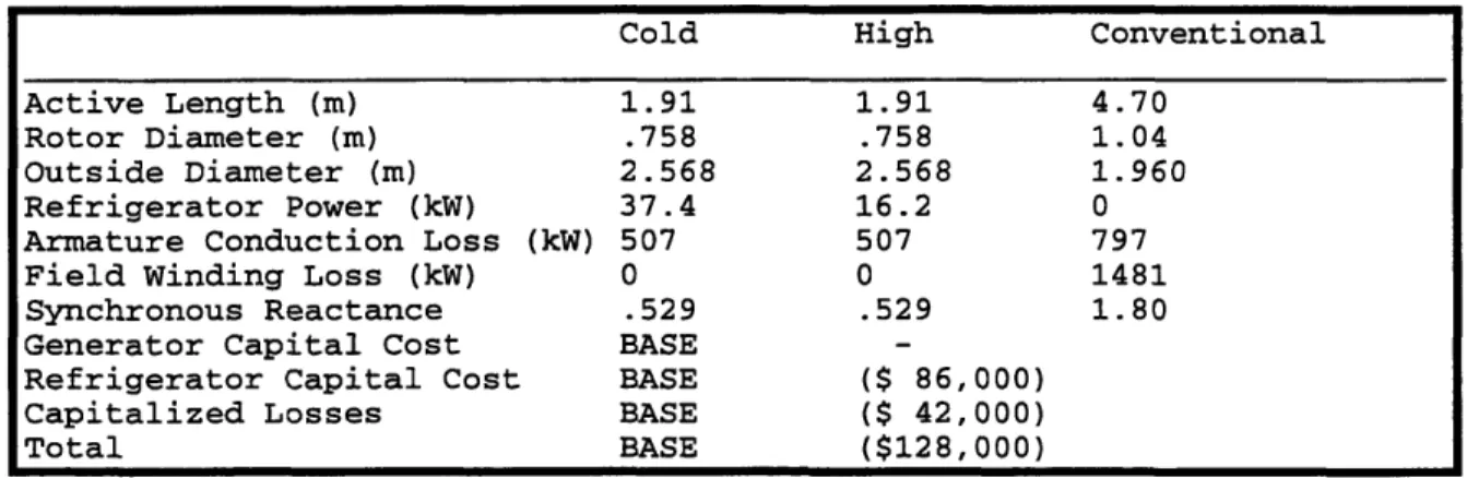
Table 1.1: Comparison of Superconducting and Conventional Generators
Cold High Conventional
Active Length (m) 1.91 1.91 4.70 Rotor Diameter (m) .758 .758 1.04 Outside Diameter (m) 2.568 2.568 1.960 Refrigerator Power (kW) 37.4 16.2 0 Armature Conduction Loss (kW) 507 507 797
Field Winding Loss (kW) 0 0 1481
Synchronous Reactance .529 .529 1.80
Generator Capital Cost BASE
-Refrigerator Capital Cost BASE ($ 86,000) Capitalized Losses BASE ($ 42,000)
Total BASE ($128,000)
In Table 1.1, the column labeled "cold" designates a machine similar in concept to the one developed at MIT. Namely, this generator is built with superconducting
wires capable of operating at liquid helium temperature (4.2 K) and carrying
1.6*108 A/m2 in a flux density of 6 T. The column labeled "high" refers to a
hypothetical "high performance and high temperature" superconducting generator
capable of achieving the same performance characteristics as the "cold" machine
while operating at liquid nitrogen temperature (77 K). These two machines are
compared to the "conventional" copper and iron design.
The data contained in Table 1.1 unambiguously quantifies some of the advantages of the new technology. Thus, an energy investment into a
refrigeration system returns an advantageous zero field winding conduction loss. Although the superconducting machine is more compact than
conventional generators, it is slightly larger in diameter in order to operate near "tip speed". On the other hand, the larger flux produced permits a
shorter active length for the stator and thus lowers the armature losses. Hence, it is indisputable that, despite the assumptions made in the table, the application of superconductors to turbomachinery offers significant benefits to modern utility companies.
1.2 Description of the MIT Rotor
At the heart of the 10 MVA Superconducting generator developed at
MIT lays an "advanced concept" rotor. In this section we will briefly describe
this rotor and highlight the advances in the design and shielding of the superconducting windings as well as its cryogenic cooling system.
The generator rotor, which carries the superconducting field windings, the helium reservoirs and two electromagnetic shields, rotates in an
insulating vacuum enclosure formed by the bore tube of the armature and the vacuum shaft seals at each end of the rotor. The rest of the generator, which consists of a stator winding and a magnetically shielded generator casing, is mounted radially outward from this stator bore tube, as shown in
Figure 1.1. The rotor itself rotates on room temperature tilting pad bearings
(see Picture 1.1) which are supported by two pedestals located on both sides
of the machine.6
The MIT rotor, which is depicted in Figure 1.2, is a complex machine composed of several concentric "layers" of main components whose radial
dimensions are tabulated at the end of this section. At the center, a helium inlet tube, connected to the helium reservoirs of the rotor cooling system, runs the length of the device. This system is in turn composed of two subsystems, one to cool the field winding and the other to cool the damper winding and can shield, which are connected in series under steady-state conditions.7 8 Contrary to most rotors designed in industry, all of the rotating
Figure 1.1: Schematic view of 10-MVA generator configuration HELIUM RESERVOIR TORQUE TUBE -FLOW DISTRIBUTOR -DAMPER LEADS -\ DR1I E SHAFT ISOLATION LAYER - COPPER CAN SHIELD
r- FIELD WINDING HELIUM RESERVOIR - TOROUE TUBE - FLOW DISTRIBUTOR r- SHAF.SEA_ BEARlhG, JOURNAL J
SHAFT SEAL BEARING FIELD LEADS JOURNAL J J/
HELIUM TRANSFER COUPLING -J LIOUIO HELIUM INLET
Figure 1.2: Cross-Section of the 10-MVA Rotor
Generator rotor in bearings
Picture 1.2: Superconducting field winding
20 Picture 1 : / . N.. I I v% " , 11 .A , I I I ". !' I - x . . -. I
elements in this machine (i. e. the winding and the two shields) operate at nearly liquid helium temperatures.9 Radially outward of the helium inlet tube and axial reservoir, lays the inner support tube. This tube, as well as the outer support tube are both stainless steel forgings and thus serve as the torque carrying members of the rotor.
The principal component in the rotor assembly is the superconducting
field winding which consists of a total of 1456 (=728x2) turns in saddle
shaped modules, seven of which are mounted on each pole. Each individual
module has 14 layers of wire in the radial direction and 4 to 10 layers, depending on its position on the pole, in the azimuthal direction. The wires, which are composed of 480 Nb-Ti strands, measure 63 microns in diameter
and are embedded in a copper matrix. This field winding is retained between
the aforementioned support tubes by a set of yokes capable of transmitting
the steady-state torques acting on the winding to the main rotor body while at the same time insulating it from transient forces and torques. The MIT
field winding shown in Picture 1.2, is capable of generating a magnetic dipole field of 4.8 T at a rated current of 939 Amperes.'0
Two shields envelop the field winding. The single sheet of solid copper
which forms the copper "can" shield, innermost of the two, serves to protect the superconductive windings from alternating magnetic fields. Like all
metals, the copper can develop image eddy currents governed by Faraday's
law" (V = E.-ds = --_m) which increase until the penetrating field is
dt
canceled. Hence, this rolled copper sheet must have a low and continuous
resistance throughout the cylinder, while being strong enough to transmit very high levels of torque from the damper shield assembly to the support tubes during faults.
The wound damper shield, or main shield, is a two phase two circuit herringbone form winding operating at about 5 K. The winding, which is 60
turns per phase of a cable made up of 616 insulated and transposed strands, serves two main purposes. First, this component protects the field winding by
dampening torques from 60 and 120 Hz electromecanical oscillations
originating in the stator as a result of power system transients. Second, it is
also the rotor's main source of shielding from transient magnetic fields. Since
this energy dissipation is largely achieved by using a warm dampening resistor, a thermal isolation layer protects the field winding from transient temperature rises in the damper during faults. 12
Finally, the rotor's outermost radial component is the filament wound prestressing tube. Made out of a stainless steel fiber embedded in an epoxy matrix, this element maintains a high radial compressive prestress on all
rotor components mentioned above. This compressive force keeps the two
shields in contact with the rotor even under centrifugal and magnetic
loadings. The high compressive stresses produced by this force also permit
the transmission of fault torques from the shields to the outer support tubes.'3
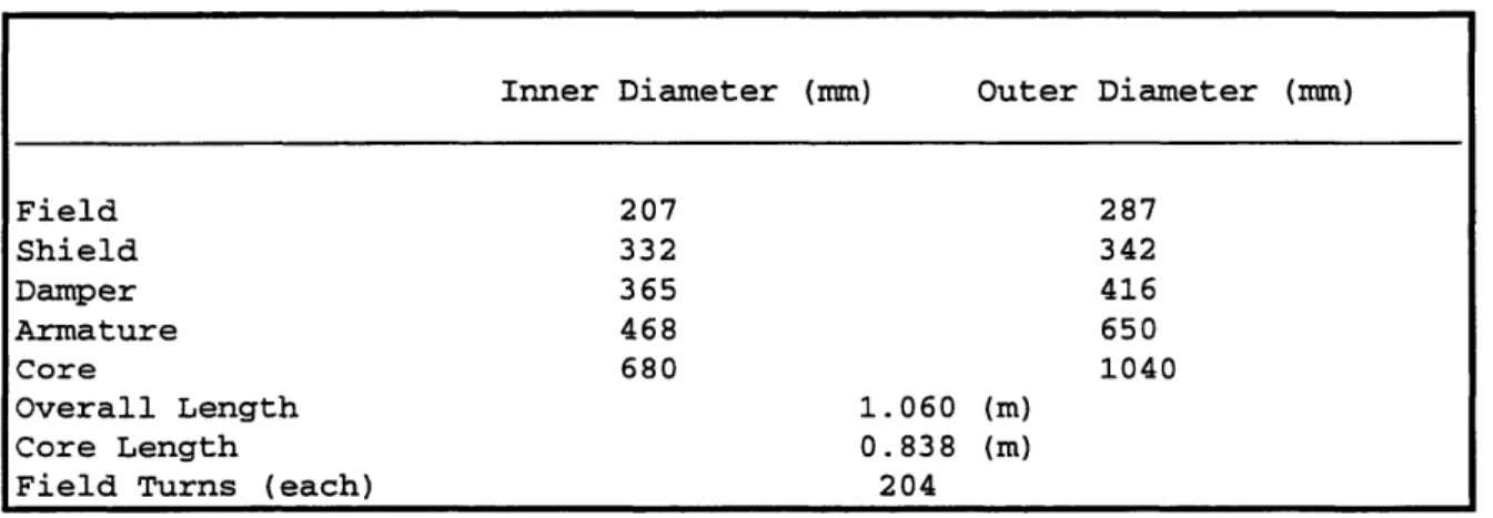
Table 1.2: MIT-DOE Superconducting generator, Major Dimensions
22
Inner Diameter (mm) Outer Diameter (mm)
Field 207 287 Shield 332 342 Damper 365 416 Armature 468 650 Core 680 1040 Overall Length 1.060 (m) Core Length 0.838 (m)
Despite the advantages listed above, namely in the field winding support, the cryogenic system and the cold shielding system, the generator's armature winding must be able to take advantage of the rotor's exceptional capabilities.
1.3 Benefits of Air Gap Armature Designs
We will begin this section by comparing conventional magnetic iron armatures to air gap ones before examining the advantages offered by this
modern design.
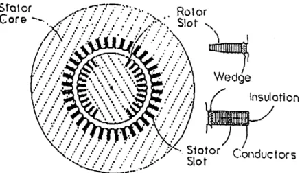
In a conventional generator, the field winding, which usually carries a constant current density on the order of 500 A/cm2, is just a hydrogen gas or water cooled electromagnet. The armature winding is located in slots within the stator core, a structure composed of thin sheets of magnetic steel, as shown in Figure 1.3. Because the steel is at ground potential, it is necessary
to insulate every conductor, thus limiting the internal voltage to about 26 kV.
Furthermore, the insulation thickness limits the slot current density to about
300 A/cm2. 14
When the generator operates under load, the rotor's rotating field is opposed by the magnetic flux created by the armature winding current. Under steady state conditions, this magnetic flux is principally a sinusoidal distribution, having the same angular frequency but lagging that of the rotor's rotation. The reactive impedance of the armature winding, which is a measure of the flux produced by the armature relative to that generated by
the field winding, is inversely proportional to the "air gap" existing between
the outside of the rotor and the inside of the stator assembly.
Since the synchronous reactance is the reactive impedance between the internal voltage and the armature's terminals, it is clear that too high a
Sta or Core
Figure 1.3: Schematic of Conventional Generator
FIel
win~
Ro
Su
Figure 1.4: Schematic of Air-Core Synchronous Machine Geometry
value will result in inferior dynamic performance, low transient stability limits as well as more frequent adjustments of the excitation current for maintaining proper terminal voltage under varying loads. Hence, in order to built a satisfactory generator, the reactance must be reduced below a certain value. This is usually achieved by increasing the air-gap distance, which in turn requires an increase in the field current in order to maintain a
comparable magnetic flux through the armature. Unfortunately, increasing the excitation current increases the I2R losses within the rotor, thus
decreasing efficiency and increasing the amount of heat that must be
removed. Inevitably this leads to a design compromise: efficiency and refrigeration load are traded off in order to gain machine dynamic
performance as well as voltage stability.'5
The application of superconductors to generators has rendered the
air-gap armature more feasible and appropriate for commercial application.
Since superconductors can produce very large fields, as mentioned in section
1.1, it is possible to increase the air-gap to encompass the entire active region
of the generator. Furthermore, superconductors are capable of producing higher flux densities than those of saturated iron, therefore magnetic iron would limit rather than enhance the magnetic flux within the machine. As a result, it is beneficial to eliminate the magnetic iron slots in both the rotor and the armature and replace them by composite (non-magnetic) "torque tubes" capable of providing torsional support and restraint from strains
caused by the large magnetic stresses imposed by the field conductors. Such a generator design is portrayed in Figure 1.4.
The first advantage gained by eliminating the magnetic iron is the reduction in the reactance of the armature, which allows for higher currents
elimination of iron allows for more space for the armature itself thus
increasing power density and efficiency. Third, since the "ground potential" iron is no longer present, the insulation required around the bars forming the armature winding could be reduced, resulting in an even larger conductor space factor and potentially higher terminal voltages. Finally, the
replacement of iron by composite materials renders the machine significantly lighter and much simpler and cheaper to manufacture.16
In order to design an air-core machine and gain all of the
aforementioned advantages, it is necessary to add two main components not found in conventional machines. The first is the rotor magnetic shields which,
as described previously, prevent time-varying electro-magnetic fields from
entering the rotor and inducing eddy currents capable of producing losses in the superconductor. Another component called the magnetic shield, which
envelops the generator, must be built in order to confine the powerful dipole field within the machine by providing a "flux return path". It also slightly enhances the flux density in the active region.'7
It should be pointed out that hybrid generators, which consist of a superconducting rotor and a conventional iron armature, could in principal be
constructed. Except for the zero field winding losses, this machine would
behave mostly like a conventional machine in size and performance and could not benefit from the many advantages, such as the reduction in reactance
and the performance increase, offered by air-core geometry. Because of the
iron's limiting effects, the flux densities within the machine would be comparable to those found in traditional generators, hence limiting the conductor current density to about 2,000 A/cm2.
In conclusion, it is clear that the air-core armature winding is superior to the magnetic iron slot design as it resolves the traditional design tradeoff
between machine efficiency and the advantages offered by a lower
synchronous reactance. However, it is because of the superconductor's ability to produce extremely large flux densities that saturated iron is rendered
obsolete and that an air-gap design is technologically feasible.
1.4 Tvoes of Air Gap Armature Windings
Having seen the benefits inherent in air gap designs, we will now examine various types of winding schemes that are compatible with this technology before commenting on their advantages and disadvantages.
There are six major parameters that characterize an armature
winding. The first three parameters, which are quantitative in nature, are: the number of phases, the number of circuits (or phase belts) within each of these phases and the number of turns within each individual circuit. Modern large scale electric machinery almost exclusively uses three phase (each 120
degrees out of phase) voltage, thus we will concentrate our discussion only on
such machines. The fourth parameter distinguishes the manner in which the phase belts are mounted. Usually, for ease of manufacturing and for design
simplicity, generator as well as motor armatures are constructed with two
phase belts which could be mounted either in series or in parallel.
The fifth characteristic of an armature winding is the topology of the
entire circuit. There are two common methods for connecting each of the
three phases together: Wye and Delta. In a Wye connected machine, all three phases are grounded together at one point and thus four wires exit the
generator. A Delta connected machine, however, has no ground since all
three phases are strung one after the other in a closed loop. Certain design innovations, particularly with delta connected machines, are capable of
potential which exists between adjacent conductors. The modifier "limited voltage gradient" is therefore added to the fifth parameter for machines thus constructed. Figure 1.5 illustrates the preceding explanations graphically.18
Finally, the sixth parameter refers to the method by which the winding, located in the active length of the armature, is made. In a lap
winding, conductors first run positive in the theta direction, then run straight before turning in the opposite direction (negative in theta) when traveling axially on the cylinder's surface. When the straight part is removed, the conductors have a "kink" half way across the armature and the assembly
appears like a chevron. The wave winding is similar to the lap winding, with
the exception that, after passing through the straight section, the conductor continues in the same direction as it had begun. It can be shown that in both layouts, the conductors travel through the same "slots" and "capture" the
same amount of flux. A helical winding is essentially, a wave winding who's
straight section has been eliminated.
The most common arrangement found in conventional iron core
generators is the Wye connected lap winding design with multiple parallel paths, each comprised of several dozen turns.'9 Figure 1.6 illustrates an
armature of this type, drawn with two phase belts and only six turns per
phase. This type of design is well suited for a conventional generator for two
reasons. First, the use of the common lap type winding allows for simple modular construction thus reducing manufacturing costs. Second, the use of a
Wye connection allows for the minimization of circulating currents,
particularly those due to third harmonics, by providing a common ground to
all three phases. By following the conductors through the active region represented in Figure 1.6, it becomes apparent that there are large voltage differences between both radially and azimuthally adjacent conductors.
Figure 1.5: Topology of Wye and Delta Connected Three-Phase Winding a) Wye Connected Parallel Circuit
!
i-01cJ r-.Ha u U a) tsl
a)-0
Furthermore, as conductors carrying nearly the full machine voltage will
inevitably cross conductors of another phase, even larger voltage differences
exists in the end turn region. In a conventional machine, where each bar is insulated from the core and where the rated voltage is comparatively small, this design is justified. However, in the case of an air gap winding, which does not have a core, the conductors must each be heavily insulated to endure the rated voltage.20
In order to reduce the need for turn to ground insulation, the Wye topology must be abandoned and the Delta connection scheme, which has no
"common ground", must be adopted. By modifying only the end connections of
the previously depicted winding, we arrive at the delta connected design illustrated in Figure 1.7.
Unavoidably, this design suffers from several large voltage gradients
within the machine. Large potential differences are especially prevalent in
the end connections of phase belts, where a conductor of one phase belt
shares a "slot" with that of another. Furthermore, within the active section, there are six regions where adjacent slots will carry conductors belonging to
different phase belts. These azimuthally separated conductors, will be at greatly different potentials since one would be starting its journey through the machine while the other would be finishing it. Finally, a third type of voltage gradient exists, for a similar reason, between the radially separated conductors within a "slot" that belong to different phase belts of the same
phase. All three of these problems are manifestations of a single cause: all of
the phase belts are wound in the same sense. Figure 1.7 represents a left handed winding since entering the left end of the belt causes a rightward progression through the armature.21
J
-0 -J -rl .Ha) 1D O3 04 H cJ-I r4 e a) .HU H -I-, C-) Ha Ha) '-4 P4 I roa) -1:: 0 U I (d r-1: .rA r14 N c(YThe use of alternated sense phase belts was first suggested by Bratoljic22 in the late 1970's as a solution to minimizing the voltage
differences occurring at phase junctions and in the active region. Figure 1.8 displays the Bratoljic "limited voltage" armature winding scheme. The
insulation requirements of such a winding are reduced substantially
compared to regular designs. since bars need only be insulated for bar-to-bar
voltages. However, an insulating cylindrical shell must be inserted in order to radially insulate the end connections of one layer from those in the next. Two more shells must also be placed at the inner and outer radii of the armature to act as ground wall insulation. Westinghouse Corporation used
this type of design in a 5 MVA superconducting generator.2 3, 24
Despite its seemingly ideal design, the Bratoljic winding suffers from a geometrical problem. Bars that are closely packed together in the straight section will not fit in the end turns. This problem can be solved in either of
two ways. The simplest solution, which Bratoljic recognized, involves leaving
space between bars in the active section, just as in conventional armatures. A more complex solution, which was integrated in the Kirtley design advocates an increase in the radius of the bars located in the end turn region, in order
to gain additional azimuthal space. In the Kirtley2 5winding, a dumb-bell frog
leg configuration represented in Figure 1.9, the two layers of bars in the active section split into four "sub-layers" in the end turns. Since the
difference in potential between radially adjacent bars is one turn voltage and that between azimuthally adjacent bars is two turn voltages, this design is subject to the same insulation requirements than the Bratoljic winding. A 3 MVA demonstration winding has successfully validated this design.26
Since Wave-wound armatures operate more satisfactorily than do
4-10 Cld a, ,-t -J -, -, C) --I,a) H Q). r0 W14
a) r-i .H ~4 s1 , U) on -Ha, Q4 0 H a) a) -H 7" .H .,rl ) a) rd 74 0 a) 0) a) -HH 0 a) -H ril L4 )
provided that the current per circuit does not exceed 300 Amperes. A delta connected wave winding is illustrated in Figure 1.10. The manufacturing disadvantage characteristic in such type of winding can be mitigated, or even eliminated by using discrete bars rather than continuous conductors. It is
apparent, however, that the wave winding suffers from the same problem (of
end connections taking more azimuthal space than the straight section) than
the lap winding.2 7
To make maximum use of the advantages offered by the
superconducting rotor, the armature must have as much copper as possible in the active region. A helical winding, which is essentially a wave winding
without the straight section, eliminates helically spiraling end turns
altogether, thus liquidating the aforementioned problem. In such a design, the line-to-line crossings are located in the active region rather than in the end turns. Furthermore, the electro-mechanical stress inside is distributed sinusoidally along the machine, with zero stress at the center and ends.28
While the wave winding displayed in Figure 1.11 is not of a "limited voltage" design, for the same reasons as given for the second winding, it is
possible to modify the end connections so that the armature produced in
Figure 1.12 represents such a winding. The MIT 10 MVA Superconducting
generator armature, which was built two years ago, was constructed in this fashion.
Like the Bratoljic scheme, the insulation requirements in this winding
call for turn-to-turn voltages for the bars, for cylindrical shells capable of
line-to-line insulation and for two line-to-ground insulating shells placed at the inner and outer radii of the armature. The helical winding offers,
however, a much more efficient use of the armature's internal volume since
t -r. I'd -rH a) 4-) C). a) rDu H Ha1) r-I r-4 rd U C~4(O a) u Q)
r.
0 C-U I ra 4-H a) 0 r4 a) -H r1 en (Y(D re) O 0) NC
0
-H ;H -Ho U) 4 4Jl C *-H u -I4
4) (UCD: -I
r
rd 4J rd aJ) -IH a 4 .,, ! t 1U e -e e a) s-m CD O It0
a) co - rr Cr4 Ithe active region is not filled with unnecessary insulation while the end turns are cramped together.
Having followed the evolution of monolithic windings, we will now
describe three completely different types of winding patterns. The first
winding design is the modified Gramme-Ring2 9 design which was proposed by
Kirtley and Steeves. As illustrated in Figure 1.13, the nature of this winding is toroidal, with conductors wrapped around a ferromagnetic core. Since this
winding is composed of alternated sense phase belts, it is also a limited voltage gradient design.30 Since conductors do not cross each other in this
winding, the insulation requirements are reduced to core insulation and to insulating cylinders at the inner and outer radii. This armature winding, unfortunately, suffers from unacceptably large electromagnetic losses and large reactances.3'
Figure 1.14 depicts another scheme, called the "Spiral Pancake"
winding, which was first proposed by Aicholzer32 and later adopted by
Westinghouse3 3 for a 300 MVA machine. This three phase design is composed of six spirally shaped pancake-coil phase belts, two of which form each phase,
interleaved around a central cylinder. Each phase belt is comprised of two pancake coils, one spiraling into and the other one spiraling away from the
center of the machine. The pancake coil is, in turn, composed of two circuits, each occupying different radial positions. The phase voltage is developed
through a complicated set of series and parallel connections within and between phase belts. An advantage of this winding is its ability to be Wye connected, without causing adjacent bars to be at great potential differences. Since the maximum difference in potential at the inner bore tube is half the phase to neutral voltage, the insulation requirements call for one turn
voltage bar-to-bar insulation within pancake coils and for line-to-line voltage
II
CORE
A
C
a
Armature Outer Radius Ro
Armature Inner Radius Ri
a) Half Pancake
b) Axial View of Pancake Layout
Figure 1.14: Spiral Pancake Winding
between pancake coils. Unfortunately, cooling through four layers of high voltage insulation, especially in this geometry, is an inefficient process.34
The last design, called the "Coaxial Turn" winding, was also invented by Aicholzer3 5. The radical design consists of six concentric tubes, connected
in series by specially design end connectors. This Wye-like connected machine requires much less insulation since the machine terminals are brought out at the inner and outer radii. Since this revolutionary design is
impractical to manufacture on a commercial scale, we will not detail it further.
1.5 Introduction to MIT Designs
Based on the various types of air-gap armature windings outlined in the previous section, the MIT group has constructed several different
armature windings during the life of this project. A 60 kVA model, which was
constructed in 1979, demonstrated the ability to design, construct and test
an "advanced concept" armature. The design, which incorporated a helically
wound delta connected limited voltage gradient armature, helped develop important construction techniques. For example, the thin Roebel transposed magnet wire used in the conductor bars had to be edge brazed to a flat plate and bar group moldings had to be made. In addition, the use of a silicone
transformer fluid (Dow Corning #561) as an insulating and cooling medium
was demonstrated. The theoretical values computed for inductances, synchronous reactance, armature resistance, temperature rise in the
armature conductors and field current to achieve no-load voltage compared
favorably to the experimental data. Unfortunately this apparatus was unsuitable to test the major insulation's performance and to test the structural integrity of the armature.36
A 10 MVA delta connected, helically wound limited voltage gradient
armature winding, resembling the 60 kVA experiment, was subsequently constructed to the specifications listed in Table 1.3.
Table 1.3: MIT 10 MVA Superconducting Generator High Voltage Armature Design Specifications
Unfortunately, this armature suffered from a turn-to-turn flashover
before any significant tests could be conducted.
The goal of this thesis is to design a new armature for the 10 MVA
machine while pioneering new concepts and techniques applicable in the
construction of a commercially viable generator. Hence, the specifications and
a detailed layout of this armature will be generated in the next chapter.
44 Rating: 10 MVA Phase Voltage: 13.8 kV Phase Current: 245 A Number of Phases: 3 Number of Circuits: 2 Arrangement: Parallel
Turns per phase: 204
Connection: Delta
Number of armature bars: 2448 Conductors in each bar: 24
Elementary conductors: round copper magnet wire, AWG #21 Roebel transposed with pitch length of 2"
CHAPTER 2 ARMATURE DESIGN
2.1 Design Specifications
The new 10 MVA armature winding, which will be designed to replace
the damaged armature, must fit between the existing stator bore tube
sketched in Figure 2.1 and the magnetically shielded generator casing. The
winding itself will consist of three helically wound Wye connected phases,
each composed of two phase belts (circuits) mounted in series. By mounting the two phase belts in series, rather than in parallel, the generator can produce a higher terminal voltage so that lower ratio step-up transformers may be used. In addition, this arrangement eliminates circulating currents caused by uneven current flow through parallel circuits. A diagram of the
circuit topology is depicted in Figure 2.2.
Despite the apparent disadvantage in replacing an advanced design limited voltage gradient armature with a simpler design, the Wye connected machine avoids some of the drawbacks and mitigates the risks involved in high voltage armatures. An obvious advantage inherent in Wye connected armature windings is the reduction in the machine internal and terminal voltages. A lower internal voltage not only reduces the chances of electrical flashovers but also reduces the need for the thick cylindrical insulation layer present in the high voltage delta connected armatures. Hence, it may be possible to increase the space factor of the armature and gain additional generating power. Furthermore, large conventional generators still use traditional Wye designs as they minimize circulating currents and reduce third harmonic losses. The two major drawbacks of this simpler design, when
ow-I I J I ° ci z I II . 01
I ^
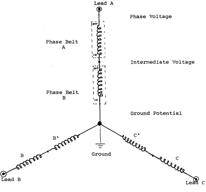
o li. c'V. OCo 1 i. .I .4C ,. e a wIi -..1 to ,! 0 0CD a :1 0 W Al L I V I ILead A Phase Voltage Phase Belt A Intermediate Voltage Phase Belt B J Ground Potential C' B' Ground C B C
Figure 2.2: Circuit Topology of the Mit 10-MVA Wye Connected Armature Winding
Note: This generator design is based on a. Wye
connected, 2 serially mounted phase belts, 3 phase layout. Each phase belt is composed of 17 turns. B I i i I I I I I I
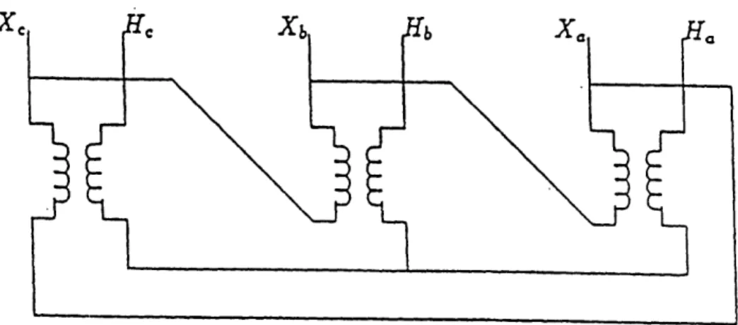
large step-up transformers and the much higher I2R losses. An example of a typical connection to a transformer block is depicted in Figure 2.3. Typically,
a generator of this type is connected to the delta side of the transformer and
the transformer's Wye side is impedance grounded.
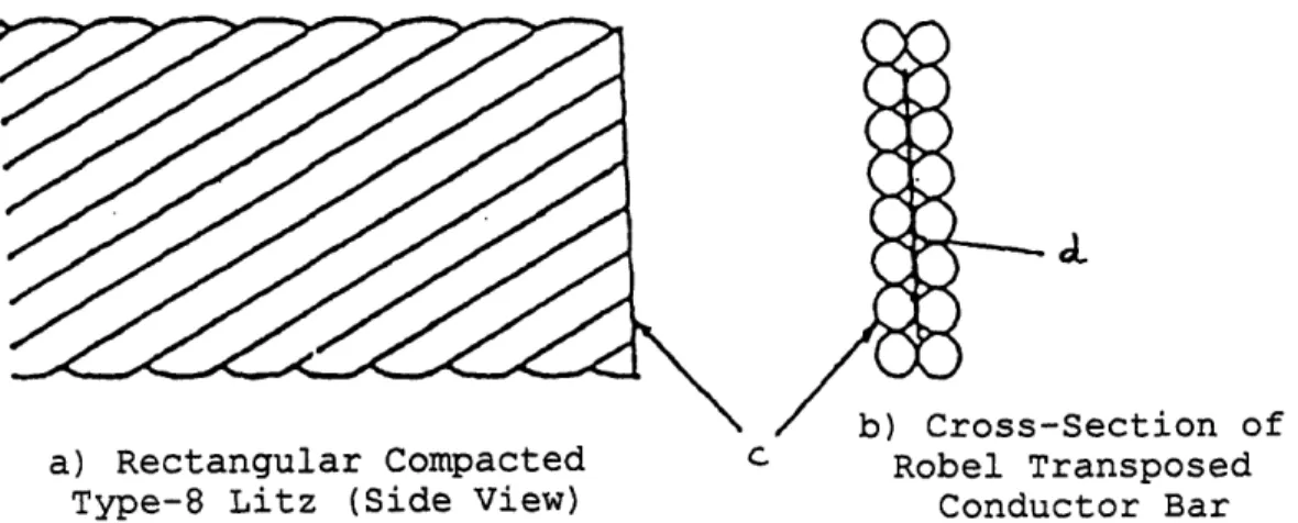
A qualitative selection of the conductor to be used in the bars forming the armature winding may be made next. The conductor will be comprised of a rectangular compacted Litz, which refers to a wire consisting of a number
of separately insulated strands, or bundles of strands, which are bunched together such that each strand tends to occupy all possible positions
throughout the cross section of the conductor. This Roebel transposition
results in equalizing the flux linkages, and hence the reactances of the individual strands, thereby causing a uniform current distribution
throughout the conductor. A sketch of a rectangular compacted (type 8) Litz
wire, which has been developed and patented by New England Electric Wire Corporation, is given in Figure 2.4.
Since the primary benefit of a Litz conductor is the reduction of AC losses, the first consideration in any such design is the operating frequency. Since higher operating frequencies require a smaller diameter wire in order to maintain eddy current losses at a tolerable level, it is used to determine the maximum diameter of the individual magnet (film insulated) wires. These eddy currents tend to travel at the surface of conductors and thus
reduce the effective current-carrying cross section. Therefore, the ratio of AC
to DC resistance, which should ideally be near unity, and which is
proportional to
x = 0.271 x D -'T Where D is the magnet wire diameter in mills, F is the operating frequency in Hz and x must be no larger than 0.25.
x
Figure 2.3: Delta-Wye Transformer Connection
Note: The Wye Connected Armature Winding is Typically Mounted to the Delta Side of the Transformer.
49 __
Figure 2.4: Conductor Used in Armature Bars
Ci
a) Rectangular Compacted c
Type-8 Litz (Side View)
-Section of Robel Transposed
Conductor Bar
c) Bundle of 19 Conductors
d) Cross-Section of 19 Conductor Bundle
is a good indication of the effects of eddy currents. Operating at 60 Hz, the armature of the superconducting generator will be designed with AWG #20 or #21 copper magnet wire.3 7 This wire must be film insulated with a material that has an excellent film flexibility and abrasion resistance, has good electrical properties, can operate at moderate to high temperatures and can be solderable.
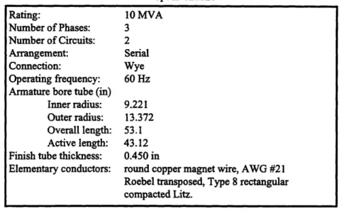
Table 2.1: MIT 10 MVA Superconducting Generator Armature Design
Specifications
Table 2.1 contains a recapitulation of our initial design specifications for this armature winding. In the following sections, the physical layout of the machine will be exposed in qualitative terms before a thorough
quantitative design analysis.
2.2 Layout Detail
A helical armature winding physically consists of layers of insulated conductor bars which twist 180° while traveling along the length of the
cylindrical armature. Half of the layers of the armature are composed
exclusively of right handed bars, while the other half is formed by left handed bars as shown in Figure 2.5. In order to link the rotor flux, a right handed
Rating: 10 MVA Number of Phases: 3 Number of Circuits: 2 Arrangement: Serial Connection: Wye Operating frequency: 60 Hz Armature bore tube (in)
Inner radius: 9.221 Outer radius: 13.372 Overall length: 53.1 Active length: 43.12 Finish tube thickness: 0.450 in
Elementary conductors: round copper magnet wire, AWG #21 Roebel transposed, Type 8 rectangular compacted Litz.
0 c,--,1 .,-C) -o at, N Ln
bar of one layer must be connected in series to a left handed bar of another
layer so as to form a complete loop. Consequently, this type of winding must be composed of an even number of layers. The number of bar layers depends
on the number of turns required to achieve the machine terminal voltage, the physical size of the insulated bar, the armature's circumferential length and the desired machine reactance. In order to maximize the present generator's
space factor, only two layers of bars shall be used.
The helical winding, which resembles the traditional wave design,
eliminates the need for circumferential end windings that occupy a lot of space at the ends of conventional armatures. Instead, the end connections in helical armatures consist of flat copper tabs, located at the ends of the
machine, which connect the appropriate layers of bars. This design produces a cylindrically shaped monolithic armature with a constant radius, which could be encased in a non-metallic support tube.
However, unlike conventional iron core armatures that leave space
between the bars in the active (straight) section, the helical armature must pack the bars together as closely as possible in the active region (where they are helically spiraling) in order to achieve the highest efficiency, terminal voltage and power density. Since the circumferential length available for the insulated bars is the same in the active section as in the end region, it is
possible to gain some additional space for the end connections by
straightening the ends of the bars. Hence, the bars used in this air-gap
winding are composed of three sections: a central "helical portion" which is
situated in the active section of the machine, a straight "end region" where the end connectors may be attached and an "end turn" region which serves as a transition between the two aforementioned sections. Picture 2.1, which
Picture 2.1: Close-up of the End of the 10 MVA Limited
Voltage Gradient Armature
(Note the three sections of the bar)
represents a close-up of the ends of the 10 MVA limited voltage gradient armature, clearly illustrates these three conductor bar sections.
Being that the radius of the armature is large compared to the width, W, of the insulated bar, the circumferential distance, D, occupied by the bar
is:
Dhelical = W in the helical section, and Dend = W for the straight end section,
cosO
as shown in Figure 2.6. Thus, the space gained by straightening the bars is proportional to the cosine of the helix angle. From the data supplied in Table
2.1, 0 is approximately:
circumference 2I x 9.221
0 = ctan length = arctan) = 47 degrees. Therefore, the space
reduction factor is about 67%.
The armature itself is composed of a total of six individual phase belts (circuits) which are distributed at the "lead" end of the stator, as shown in Figure 2.7. Since each complete turn is composed of an upper and a lower bar, the upper bars of one phase belt complement the lower bars of the other phase belt of the same phase, at the end of the armature. In addition, in order for the two circuits to deliver the same induced voltage at the same phase angle, the two complementary phase belts must have the same number of turns and be located diametrically opposite to each other (with respect to
the cylindrical stator's long axis) throughout the machine. For example, if
the two phase belts comprising the first of the machine's three phases are labeled " A " and " A'", the bars of" A " pass above the bars of " A' " in a
location half way across the armature, while the converse happens at the
diametrically opposite location. Because of the requirement to complement
upper and lower bars, helical armatures must be designed with an even number of phase belts within each phase. Furthermore, because of the need
I _ m U .H a) U) $4 U) -I r-r ::5 .1 l W O -. 0 C-q r. ,-H --I a) 4J E a) 4J 4-) c-,o. a. I a) sI zL .
A\ _ _
I IF} Ln 3 , L -> Io 0 m o C0 C 43 -m l). : 4i Q) U) a) *. Q. L. 0 ow -o 0
to electrically combine the two circuits, the two phase belts of a given phase
are placed diametrically opposite to each other. Breaking down each phase of the generator into two individual phase belts offers yet another advantage. The current flowing in the alternating left-handed and right-handed helically spiraling bars in a phase belt possesses, in addition to the axial component, a
small net azimuthal component due to the magnetic field's dependence on
radial distance. This could create an axial magnetic moment, which would lead to an uneven loading of the rotor, if it were not balanced by the other phase belt that has been wound in the opposite direction and is situated on the other side of the armature.38
Having described the various geometrical aspects involved with helical windings in order to arrive at the armature's physical layout, we will now concentrate on the electrical and cryogenic issues. Since the present Wye connected generator must be designed with three diametrically opposed and serially mounted pairs of phase belts, only two possible phase belt
arrangements may exist. As depicted in Figure 2.2, we have adopted a
convention where primed phase belts are grounded at one end and connected to the non-primed belt of the same phase at the other end. The voltage
differences that can exist at the interface between any one of five combinations two phase belts, taking account of phase differences, are reported in Table 2.2.
Hence, the optimum deployment for the phase belts is an alternating
sequence of primed and non-primed belts, such as: A, B', C, A', B, C' and arranged as in Figure 2.8. The only other possible arrangement, which
would consist of keeping the primed and non-primed belts contiguous to each
other (i.e. A, B, C, A', B', C'), has been rejected because full line-to-line
voltages would be incurred between the phase belt terminals. By combining
TABLE 2.2A
VOLTAGE GRADIENTS OCCURRING AT PHASE BELT INTERFACES Type of
Interface
Phasors Calculations
Medium to Ea/2 Vi= Ea/2 0.5
Ground (*) O 0 (Best)
Mediu_
to.
Medium to Medium Ea/2\
120' Ea/2 2 V2= -Ea/4 I EaV3/4 3Ea/4 0.866 -EaV!/4It-V
I2
=Ea5/2
IHigh to Ea Vl=Ea Ground 0o 1.0 . _ _ ~ ~- 4 High to Medium (*) E Vl= Ea/2 V2= -Ea/2 t-V2Ea II -A1 -V12 1.323 IIV1-V211 =EaV/2 It High to V1= Ea V2-= -Ea/2 High ( )j
a EaV/2 Ea 120 V-V2= 3EaL2 1.732 Ea : 1 EaVV3_/2 (Worst) Ea--EaV3~~~~~~~~~~~~~~~~~~~~~~~~~~~~~~~~~~~~~~~~~~~~~~~~~~~~~~~~~~~~~~~~~~~~~~NOTE: Ea is the machine phase-voltage.
(*) Indicates the types of interfaces that occur in our wye armature design
(-) the high-to-high interface, which results in full line to line voltage, does not appear in our design due to the alternation of primed and non-primed phase belts.
Results
Table 2.2B: Voltage Gradients Occurring at Phase Belt Interfaces 60 Medium High To Ground 0.5 1 To Medium 0.866 1.323 To High 1.732
l0 T5-0 sk U o 4 u a) 0m 0 4-I 4-os . f) -4 :3 ta N ,4 1) ,L .,, 4J 0)U) -oz 0 a) 4-) r1 a) c
the aforementioned design specifications, a model of the circuit layout is
obtained and displayed in Figure 2.9.
The insulation requirements for helical armatures in general, can be separated into seven categories.3 9 The first requirement involves insulating
the basic conductors that compose the armature bars. Although these thin copper wires are roughly at the same potential at any given place, they must be individually insulated in order to prevent the formation of eddy currents. Physically, this insulation typically consists of a thin layer of film or of fiber.
The second requirement consists of insulating the bars themselves from each
other. Hence, at minimum, the bar insulation must be designed to withstand
one turn voltage. However, as described above, azimuthally adjacent bars of
two different phase belts or radially adjacent bars of opposite helix direction may be at vastly different electrical potentials, especially in non-limited voltage gradient designs.
Therefore, in complex high voltage multi-layer helical armatures, two
more insulation requirements can exist: a set of thin minor insulating cylindrical shells and a single thick major insulating cylindrical shell. The minor layers, which are placed between layers of bars having the same helix
direction, must be designed for slightly more than one turn voltage. On the
other hand, the single major layer is located between the layers of bars of
opposing helical winding direction and must be able to insulate the full line-to-line voltage.
The fifth type of insulation that is commonly used in helical armatures is called the ground wall insulation. Since, during normal operation, the generator and the stator's support tube can be assumed to be at ground
potential it is apparent that the simple bar to bar insulation, designed for one turn voltage, is inadequate. The ground wall insulation layers consist of two
4J 0 i ! d O 0o 0 0 '4 4-) Q)To rd7 0 g N Vr
cylindrical shells which envelop the conducting bars. Since both the inner and outer shells must only be rated line-to-ground, they are slightly thinner than the major insulating layer. Figure 2.10 illustrates the aforementioned
insulation components for the case of the high voltage (13.8 kV) 10 MVA
armature winding developed at MIT.
After much consideration of the aforementioned insulating options, it has been determined that the optimal insulation scheme for the MIT 10 MVA armature will solely consist of a thick bar insulation rated for line-to-ground insulation. This simpler scheme offers a number of benefits. First, the need for ground wall insulation is eliminated as each individual bar is already insulated line-to-ground. Second, the thick major insulation layer is no longer necessary since the two layers of bars are mutually isolated by twice the
to-ground voltage. This combination of insulation is slightly superior to line-to line shielding. Thirdly, by designing the entire armature with only one pair of bar layers, the need for minor layers is also eliminated. Hence, this
conservative design offers an armature with a simple layout, a higher space factor, an ease of manufacturing and a lower production cost.
The remaining two insulation requirements, which will be
implemented in our design, concern the end connections and the coolant. The end connections, which must be insulated from each other, require only turn-to-turn insulation, when they are located within a phase belt. However, as discussed above, the end connections which are adjacent to end connections belonging to another phase belt must be insulated for phase-to-ground voltage. This "boundary" between adjacent phase belts is one of the areas of highest electrical stress in this armature design.
The heat generated within the conductors is mostly due to Joule effect losses and must be eliminated in an efficient manner. Although individual
tjvfl oall tion [ation olation er Lnor nolat ion ayer Ground all Insulation Filament ound tator or e Tube
: Insulation ystems Compatible
it
Fg~-~ AirGa Armature