Deriving safety constraints for integration of Unmanned
Aircraft Systems into the National Airspace
by application of STECA
by
Yusuke Urano
B.E., Aeronautics and Astronautics, The University of Tokyo, 2010 Submitted to the Institute of Data, Systems, and Society in partial fulfillment of the requirements for the degree of
Master of Science in Technology and Policy at the
MASSACHUSETTS INSTITUTE OF TECHNOLOGY June 2016
© 2016 Yusuke Urano. All rights reserved.
The author hereby grants to MIT permission to reproduce and to distribute publicly paper and electronic copies of this thesis document in whole or in part in any medium
now known or hereafter created.
Signature of Author:
__________________________________________________________________________ Technology and Policy Program
May 6, 2016 Certified by:
__________________________________________________________________________ Nancy G. Leveson Professor of Aeronautics and Astronautics Thesis Supervisor Accepted by:
_________________________________________________________________________ Munther Dahleh William A. Coolidge Professor, Electrical Engineering and Computer Science Director, Institute for Data, Systems, and Society Acting Director, Technology and Policy Program
3
Deriving safety constraints for integration of Unmanned Aircraft
Systems into the National Airspace by application of STECA
by Yusuke Urano
Abstract
Unmanned aircraft systems (UAS) have been used for years especially in the military. However, the operation of UAS in civil aviation has been limited since there are a lot of uncertainties: a regulatory scheme needs to be established and associated technologies need to be developed.
This thesis contributes to both technology development and establishing a regulatory scheme for UAS by generating safety constraints using the new methodology developed by Professor Leveson and Dr. Fleming. This methodology is called “Systems-Theoretic Early Concept Analysis” (STECA) and is based on Systems-Theoretic Accident Model and Processes (STAMP) analysis, which is also developed by the professor. STECA has potential to generate more safety constraints that have not been considered otherwise in the early stage of development and this allows the producer to redesign the entire system with potentially less cost.
This thesis illustrates why and how STECA can be powerful to support integration of UAS into NAS. In addition, this thesis actually demonstrates how STECA derives safety constraints as a case study and shows how the safety constraints should be integrated in the system development.
Thesis supervisor: Nancy G. Leveson
5
Acknowledgement
First and foremost, I would like to express my sincere gratitude to my thesis advisor, Professor Nancy G. Leveson, for providing me the opportunity to learn in the laboratory. The experience in the lab provided me new insights. More importantly, I was able to complete my thesis with her guidance and feedback. In addition, I would also like to thank Dr. John Thomas for support of learning STAMP.
I am also grateful to the faculty, staffs, and friends in Technology and Policy Program (TPP) for providing me feedback and ideas for my research.
Finally, I would also like to thank to Japanese government for providing me opportunity to study at MIT. This 2-years’ experience will be extremely valuable for me.
7
Contents
List of figures ... 9
List of tables ... 11
Chapter 1 Introduction ... 13
1.1 Challenges of integrating civil UAS into NAS ... 13
1.2 Introduction of STECA ... 16
1.3 Research objectives and thesis overview ... 20
Chapter 2 Literature Review ... 21
2.1 System safety of UAS ... 21
2.2 Systems engineering and concept of operation ... 26
2.3 Other hazard analysis technique ... 29
Chapter 3 Application of STECA ... 31
3.1 Scope and Approach ... 31
3.2 Assumptions in FAA ConOps ... 33
3.2.1 General assumptions ... 33
3.2.2 Operational assumptions ... 35
3.3 Application of STECA to scenarios in FAA ConOps ... 41
3.3.1 Identification of system hazards and system safety constraints ... 41
3.3.2 Identification of control concepts ... 43
8
Chapter 4 Implications and assessment of the analysis ... 119
4.1 Implications from the safety constraints ... 119
4.2 Comparison with traditional analysis technique ... 122
Chapter 5 Conclusions ... 127
5.1 Contributions ... 127
5.2 Future work ... 128
9
List of figures
Figure 1 Global hawk (adapted from “Northrop Grumman” website (Northrop Grumman Corporation 2016)) ... 13
Figure 2 Annual UAS market size in each sector estimated by AUVSI (adapted
from “The Economic Impact of Unmanned Aircraft Systems integration in the United States” (AUVSI 2013) ) ... 14 Figure 3 Controller containing a model of the process that is being controlled
(adapted from “Engineering a Safer World” (Leveson 2012)) ... 17 Figure 4 the general classification of systemic factors that can be identified using
STAMP (adapted from “Engineering a Safer World” (Leveson 2012)) ... 18 Figure 5 Process of STECA (adapted from “Safety-Driven Early Concept Analysis
and Development” (Fleming 2015)) ... 19 Figure 6 Basic concept of RCFF (adapted from “Development of a Framework to
Determine a Mandatory Safety Baseline for Unmanned Aircraft Systems” (Oztekin, Flass, and Lee 2011)) ... 22 Figure 7 Types of system (adapted from “An Introduction to General Systems
Thinking” (M. Weinberg 1975)) ... 25 Figure 8 “V” model (adapted from “Systems Engineering for Intelligent
Transportation Systems” (US Department of Transportation 2007)) ... 26 Figure 9 Cost of change in each phase of system development (adapted from
“Concurrent Engineering” (Harley 1992)) ... 28 Figure 10 Boeing 747 (“13 Things You Didn’t Know about the Boeing 747” 2015) ... 32 Figure 11 Layers of separation assurance in FAA ConOps (adapted from FAA
10
Figure 12 Types of controlled airspace in the US ((adapted from FAA website (FAA
2016)) ... 38
Figure 13 Process of STECA (adapted from “Safety-Driven Early Concept Analysis and Development” (Fleming 2015)) ... 42
Figure 14 Generic role in the control loop (adapted from “Safety-Driven Early Concept Analysis and Development” (Fleming 2015)) ... 44
Figure 15 Basic control concept of surface operation ... 55
Figure 16 Basic concept of “Oceanic Point-to-Point” scenario (FAA 2012) ... 56
Figure 17 Basic control concept of “Oceanic Point-to-Point” scenario... 72
Figure 18 Process of STECA (adapted from “Safety-Driven Early Concept Analysis and Development” (Fleming 2015)) ... 73
Figure 19 the general classification of systemic factors that can be identified using STAMP (adapted from “Engineering a Safer World” (Leveson 2012)) ... 75
Figure 20 Control action of ATC ground in surface operation ... 77
Figure 21 Control action of PIC in surface operation ... 81
Figure 22 Control action of FMS in surface operation ... 90
Figure 23 Control action of ATC local in surface operation ... 93
Figure 24 Control action of ATC in oceanic flight operation ... 95
Figure 25 Control action of PIC in oceanic flight operation ... 100
Figure 26 Control action of ground control station (FMS) in oceanic flight operation ... 108
Figure 27 Control action of FOC in oceanic flight operation ... 111
Figure 28 Control action of Tower in oceanic flight operation ... 113
11
List of tables
Table 1 An example of causal factors generated from regulation in RCFF approach (adapted from “Development of a Framework to Determine a Mandatory Safety Baseline for Unmanned Aircraft Systems” (Oztekin, Flass, and Lee
2011)) ... 23
Table 2 Description of each entity in the control loop ... 45
Table 3 Control model of initiating taxi ... 47
Table 4 Control model of conflict management during taxi (Controller: ATC ground) ... 49
Table 5 Control model of conflict management during taxi (Controller: PIC) ... 50
Table 6 Control model of takeoff procedure (Controller: ATC local) ... 51
Table 7 Control model of takeoff procedure (Controller: PIC) ... 52
Table 8 Control model of landing procedure (Controller: ATC local) ... 53
Table 9 Control model of landing procedure (Controller: PIC) ... 54
Table 10 Control model of ANSP (basic information flow) ... 59
Table 11 Control model of PIC (basic information flow) ... 60
Table 12 Control model of ITP altitude change (controller: ATC) ... 62
Table 13 Control model of ITP altitude change (controller: PIC) ... 63
Table 14 Control model of ITP altitude change (controller: FOC) ... 64
Table 15 Control model of ITP altitude change (controller: UA crewmember) .... 65
Table 16 Control model of procedure crossing certain airspace ... 67
Table 17 Control model of landing procedure (controller: ATC) ... 69
Table 18 Control model of landing procedure (controller: PIC) ... 70
13
Chapter 1
Introduction
1.1 Challenges of integrating civil UAS into NAS
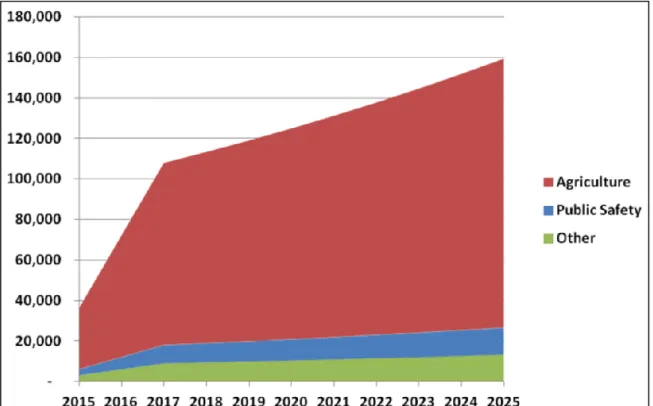
Unmanned aerial vehicle (UAV), which has been historically used in military sector such as the famous “Global hawk” shown in Figure 1 and changing its name to either remotely piloted aircraft system (RPAS) or unmanned aircraft systems (UAS) in the civil sector, is anticipated to be one of the most growing sectors in the civil aerospace industry. Association for Unmanned Vehicle Systems International (AUVSI) estimates that integration of civil unmanned aircraft systems into national airspace will create more than 100,000 jobs and make an economic impact of approximately 82 billion dollars in the US in the next decade. (AUVSI 2013) Figure 2 provides the annual sales forecast for each field. (AUVSI 2013)
Figure 1 Global hawk (adapted from “Northrop Grumman” website (Northrop
14
Figure 2 Annual UAS market size in each sector estimated by AUVSI (adapted
from “The Economic Impact of Unmanned Aircraft Systems integration in the United States” (AUVSI 2013) )
However, as AUVSI points out, one of the bottlenecks of the growth of civil UAS is the lack of regulatory structure (AUVSI 2013). Since we have not yet established the regulatory framework of integrating UAS into the national airspace, the current operation of UAS is limited in terms of its usage and its size. In order to rectify inexistence of the regulatory structure, the congress has passed the FAA Modernization and Reform Act in 2012 in the US. This act encouraged FAA to accelerate the integration of UAS into the national airspace (NAS) (Mica 2012). Mandatory for FAA includes:
15
Establishment of safety requirements for operation and certification by 2015
Establishment of six test sites for UAS
In addition, in the International Civil Aviation Organization (ICAO), Remotely Piloted Aircraft Systems Panel (RPASP) has been formed in 2014 to develop global standards to operate remotely piloted aircraft. (ICAO 2013)
Contrary to the effort of the US congress and the regulatory agencies, the progress of the integration has been limited. It is likely that there is a lack of understanding of what is required to safely operate civil UAS in the national airspace. For example, one of the most challenging parts is how to sense and avoid objects. In the manned aircraft, the pilot in the cockpit could see and avoid objects. In UAS, because the pilots are on the ground, UAS needs to somehow sense and avoid objects in other ways, but there is no established procedure, yet. Moreover, even if a procedure had been established, we are not sure of how this new procedure will induce other hazardous situations.
Traditional hazard analysis techniques such as fault tree analysis (FTA), hazard and operability study (HAZOP), event tree analysis (ETA), and failure mode and effect analysis (FMEA) are not capable of analyzing safety of UAS in this stage. This is because the definition of how the entire system works and the definition of each component involved in the system is required before analyzing the system. Since UAS that is integrated in the NAS is still a concept, these hazard analysis techniques cannot be applied to analyze safety.
16
1.2 Introduction of STECA
Systems-Theoretic Early Concept Analysis (STECA) is a new technique developed by Professor Leveson and Dr. Fleming that is capable of analyzing future concepts (Fleming 2015). The goal of STECA is to derive safety constraints by identifying potential hazardous scenarios and undocumented assumptions. (Fleming 2015) This technique is capable of dealing with the complexity of the entire system while the system is not fully matured because this technique is a top-down approach, while traditional methodology is often applicable only after system development. STECA has potential to generate more safety requirements that have not been considered otherwise in the early stage of development and this allows the producer to redesign the entire system with potentially less cost.
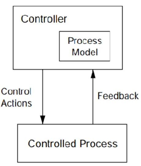
STECA is based on Systems-Theoretic Accident Model and Process (STAMP) model of accident causation, which was also developed by Professor Leveson (Leveson 2012). In STAMP, “systems are viewed as interrelated components kept in a state of dynamic equilibrium by feedback controls” and safety is assured only when appropriate constraints are enforced on the controlled processes (Leveson 2012). In this system, any controller, which includes both human and automation, contains a model of the process being controlled as shown in Figure 3 in a hierarchical control structure within the system (Leveson 2012).
17
Figure 3 Controller containing a model of the process that is being controlled
(adapted from “Engineering a Safer World” (Leveson 2012))
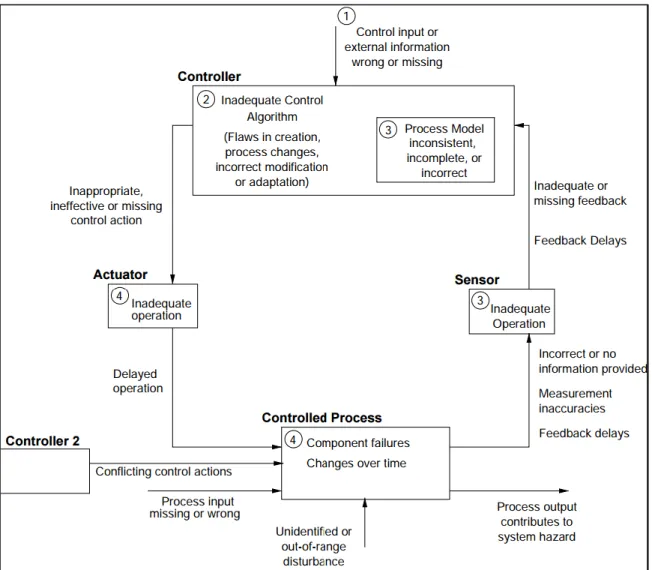
Then, safety is treated as a dynamic control problem rather than a simple component failure in a linear system. By treating safety in this manner, a top-down approach is available because analysis of how the safety constraints are enforced needs only the functionality of the system and not the detailed description of the components. Moreover, by thinking of the reasons why the safety constraints were not enforced, STAMP is capable of identifying potential systemic factors that would otherwise not have been considered. By identifying these systemic factors, new safety constraints that need to be enforced by the system are identified. Figure 4 provides the general classification of systemic factors that can be identified using STAMP (Leveson 2012).
18
Figure 4 the general classification of systemic factors that can be identified using
STAMP (adapted from “Engineering a Safer World” (Leveson 2012))
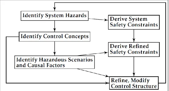
The process of STECA is shown in Figure 5. STECA uses the fundamental concepts of STAMP i.e. safety constraints, a hierarchical control structure, and process models. From the description of the concept of operations (ConOps), STECA identifies how the safety constraints must be enforced by each controller. Then STECA identifies how this control may cause hazardous scenarios by examining each controller. Process models are used heavily when analyzing each
19
control. Systemic factors that may contribute to the hazardous scenarios are identified and used to refine safety constraints.
Figure 5 Process of STECA (adapted from “Safety-Driven Early Concept Analysis
20
1.3 Research objectives and thesis overview
The research objective of this thesis is to contribute to both technology development and to the establishment of a regulatory scheme by generating sophisticated safety requirements from the ConOps of UAS. Since the traditional hazard analysis technique cannot be applied during the concept phase of the system, STECA is applied to the ConOps of UAS. The major part of this thesis will demonstrate how STECA is applied to ConOps as a case study in chapter 3. Finally, Chapter 4 discusses implications of the analysis and shows how the safety constraints should be integrated in system development.
21
Chapter 2
Literature Review
2.1 System safety of UAS
Much of the research on UAS focuses on how to assess risk of collision and how to establish requirements for UAS sense and avoid capability. For example, Melnyk assessed risk of collision by using an event tree model taking into account the probabilities of each event, such as probability of encounter (Melnyk et al. 2014). For another example, Wiebel assessed the risk of ground impact using the event tree model as well (Weibel 2004) This research made progress on quantifying risks and helping to determine the target level of safety. However, this type of research heavily relies on statistical assumptions, which does not take into account the additional complexity typical for UAS. Moreover, quantifying the risk itself does not fix how the entire system works.
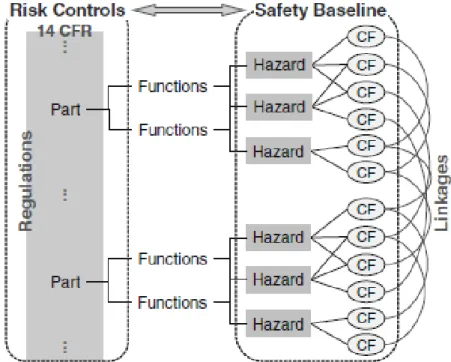
Another approach to analyze system safety of UAS has been proposed by the FAA. The FAA developed a framework called “Regulatory-based Causal Factor Framework (RCFF),” which is a qualitative analysis methodology that identifies hazards and associated causal factors on the basis of established regulation, as shown in Figure 6. (Oztekin, Flass, and Lee 2011)
22
Figure 6 Basic concept of RCFF (adapted from “Development of a Framework to
Determine a Mandatory Safety Baseline for Unmanned Aircraft Systems” (Oztekin, Flass, and Lee 2011))
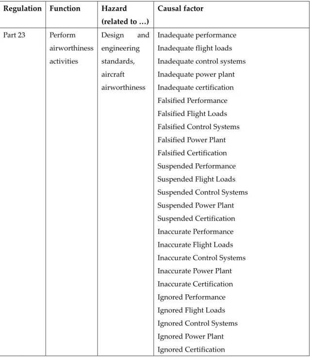
For instance, the authors provides an example of causal factors generated from regulations as shown in Table 1.
23
Regulation Function Hazard (related to …) Causal factor Part 23 Perform airworthiness activities Design and engineering standards, aircraft airworthiness Inadequate performance Inadequate flight loads Inadequate control systems Inadequate power plant Inadequate certification Falsified Performance Falsified Flight Loads Falsified Control Systems Falsified Power Plant Falsified Certification Suspended Performance Suspended Flight Loads Suspended Control Systems Suspended Power Plant Suspended Certification Inaccurate Performance Inaccurate Flight Loads Inaccurate Control Systems Inaccurate Power Plant Inaccurate Certification Ignored Performance Ignored Flight Loads Ignored Control Systems Ignored Power Plant Ignored Certification
Table 1 An example of causal factors generated from regulation in RCFF approach
(adapted from “Development of a Framework to Determine a Mandatory Safety Baseline for Unmanned Aircraft Systems” (Oztekin, Flass, and Lee 2011))
24
RCFF approach assumes current regulation provides minimum mandatory requirements for safety operation in NAS and utilizes generated causal factors to “determine a minimum mandatory safety baseline” for operation in NAS. (Oztekin, Flass, and Lee 2011) However, as the authors point out, RCFF approach does not achieve sufficient level of safety because UAS specific concern is not treated.
Compared to these research, STECA has advantage in that (1) STECA is based on systems theory, which is capable of dealing with “organized complexity” that is too organized for statistics and (2) STECA derives UAS specific safety constraints. Systems theorists classify systems into three systems as shown in Figure 7. According to Weinberg, “organized systems” are those that are too organized for statistics and too complex for analytic reduction (M. Weinberg 1975). Thus, STECA has the potential to derive insights that cannot be derived from statistics. Moreover, since STECA directly analyzes the ConOps itself, rather than comparing with existing regulations, STECA is able to deal with UAS specific safety considerations.
25
Figure 7 Types of system (adapted from “An Introduction to General Systems
26
2.2 Systems engineering and concept of operation
Systems engineering is “an interdisciplinary approach and means to enable the realization of successful systems” (International Council on Systems Engineering 2015). According to “NASA Systems Engineering Handbook,” there are often multiple conflicting interests and expectations on the systems, and thus, systems engineering serves the role of balancing the needs and ensuring an operable system (NASA 2007). Figure 8 shows the typical systems engineering process known as “V” model (US Department of Transportation 2007).
Figure 8 “V” model (adapted from “Systems Engineering for Intelligent
27
In systems engineering, ConOps play an extremely large role, especially for introduction of a new system or technology. ConOps describes the way the system works from the operator’s perspective (International Council on Systems Engineering 2011). By illustrating the ConOps, stakeholders can check whether the needs are met. Moreover, from the safety perspective, ConOps helps the analyst to derive implicit safety requirements (MITRE 2016a).
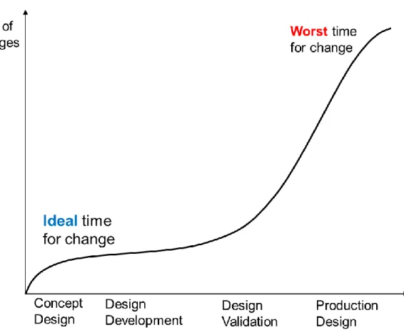
The cost of taking safety measurement is a large consideration as well. MITRE argues that “[a]lthough it is common practice to optimize the system after its built, the cost associated with implementing changes to accommodate poor performance increases with each phase of the system's life cycle” is shown in Figure 9. (MITRE 2016b) If the necessary change is found in the later stages of development, the whole project may collapse due to its large cost to rectify and/or designers have incentive to find reasons to ignore safety requirements. This is why STECA tries to derive safety constraints in the early stage.
28
Figure 9 Cost of change in each phase of system development (adapted from
29
2.3 Other hazard analysis technique
As mentioned earlier, hazard analysis techniques such as FTA, HAZOP, ETA, and FMEA are not capable of analyzing safety of UAS in this stage. This is because definition of how the entire system works and definition of each component involved in the system is required to understand how a component failure may affect the entire system. For risk assessment, probabilities are required but cannot be known for a future system for the same reason.
Functional hazard analysis (FHA) is a hazard analysis technique that can be applied in the early stage. As Wilkinson and Kelly states, “FHA is a predictive technique that attempts to explore the effects of functional failures of parts of a system. The primary aim of conducting a FHA is to identify hazardous function failure conditions.” (Wilkinson and Kelly 1998) Then the failure mode are classified by its severity and likelihood.
However, because FHA starts from a component failure, FHA does not identify hazards that do not involve a component failure. Dr. Fleming argues current methodologies provide “little to no guidance for how to identify hazardous interactions amongst components; incorrectly specified software requirements; or human operator errors due to poor design of procedures, computer interfaces, and underlying logic of automation and decision support tools.” (Fleming 2015) Moreover, identification of likelihood can be challenging, especially for a new system that does not currently exist.
31
Chapter 3
Application of STECA
3.1 Scope and Approach
In this thesis, STECA is applied to the ConOps developed by FAA called “Integration of Unmanned Aircraft Systems into the National Airspace System Concept of Operations (FAA 2012)” (hereinafter referred to as “FAA ConOps”). FAA ConOps has been developed to show how the integration of UAS into NAS will affect other stakeholders. FAA says that this ConOps can be used among the stakeholders to develop system-level requirements (FAA 2012).
Scenarios of “Surface Operations,” and “Oceanic Point-to-Point” in FAA ConOps chapter 5 are used as a case study for the analysis (FAA 2012). These scenarios include the phase from taxiing on the ground to the actual operation over the ocean. The unmanned aircraft used in these scenarios are the Boeing 747 as shown in Figure 10. This thesis will demonstrate how STECA would be applied to these scenarios as a case study.
32
Figure 10 Boeing 747 ( Ethan Wolff-Mann 2015)
It should be noted that the analysis conducted in this research is incomplete mainly due to lack of resources and information. This analysis should be refined by experts in each field. However, the author believes that this analysis still demonstrates the usefulness of STECA.
33
3.2 Assumptions in FAA ConOps
3.2.1 General assumptions
According to FAA ConOps, the following are the general assumptions identified in the document:
“1. UAS operators comply with existing, adapted, and/or new operating rules or procedures as a prerequisite for NAS integration.
2. Civil UAS operating in the NAS obtain an appropriate airworthiness certificate while public users retain their responsibility to determine airworthiness.
3. All UAS must file and fly an IFR flight plan.
4. All UAS are equipped with ADS-B (Out) and transponder with altitude-encoding capability. This requirement is independent of the FAA’s rulemaking for ADS-B (Out).
5. UAS meet performance and equipage requirements for the environment in which they are operating and adhere to the relevant procedures. 6. Each UAS has a flight crew appropriate to fulfill the operators’ responsibilities, and includes a PIC [(Pilot in command)]. Each PIC controls only one UA.
7. Autonomous operations are not permitted. The PIC has full control, or override authority to assume control at all times during normal UAS operations.
8. Communications spectrum is available to support UAS operations. 9. No new classes or types of airspace are designated or created specifically for UAS operations.
34
10. FAA policy, guidelines, and automation support air traffic decision-makers on assigning priority for individual flights (or flight segments) and providing equitable access to airspace and air traffic services.
11. Air traffic separation minima in controlled airspace apply to UA. 12. ATC is responsible for separation services as required by class of airspace and type of flight plan for both manned and unmanned aircraft. 13. The UAS PIC complies with all ATC instructions and uses standard phraseology per FAA Order (JO) 7110.65 and the Aeronautical Information Manual (AIM).
14. ATC has no direct link to the UA for flight control purposes.” (FAA 2012)
35
3.2.2 Operational assumptions
3.2.2.1 Separation assurance
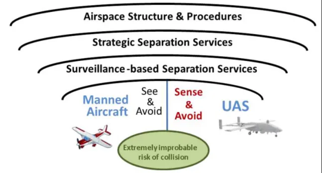
In FAA ConOps, “layers of separation assurance” has been identified as shown in Figure 11. (FAA 2012)
Figure 11 Layers of separation assurance in FAA ConOps (adapted from FAA
ConOps (FAA 2012))
In particular, FAA ConOps includes the “Strategic Separation Services,” which is one of a basic concept of Next Generation Air Transportation System (NextGen). This is a concept that ATC personnel use flight plan data to modify trajectories in advance.
In addition, because UAS do not have an onboard cockpit and humans cannot see and avoid like manned aircraft, UAS is required to have its unique sense and avoid capabilities. These capabilities “incorporate data from airborne sensors,
36
ADS-B (Out) messages, ground-based radar or other inputs.” (FAA 2012) Detailed requirements for the sense and avoid capabilities have not been identified yet, but they are required to have performance-based requirements.
Moreover, allocation of responsibilities for separation assurance have been identified depending on each class of airspace:
(1) In class A airspace, “ATC is responsible for providing separation between all aircraft. ADS-B (Out) is mandatory for all aircraft in Class A airspace. With the majority of aircraft capable of RNAV, both manned and unmanned aircraft benefit from greater flexibility available through both published routes and non-restrictive routing options. Many UA operations in Class A airspace are point-to-point flights, with aircraft whose performance characteristics and PBN flight management capabilities are similar to manned aircraft. Since all aircraft in this airspace are on IFR flight plans and are receiving ATC separation services, the UAS PIC should not have to perform a self-separation maneuver (analogous to remaining well clear). However, the PIC may request such maneuvers in response to the Sense and Avoid capability recommendations, which may be approved or modified by ATC. The UAS has an active collision avoidance capability.” (FAA 2012)
(2) In class B airspace, “ADS-B (Out) is required for all aircraft in Class B airspace. ATC is responsible for providing separation to all aircraft in Class B airspace. Separation minima between IFR aircraft, whether in IMC or VMC, are generally 3 miles laterally or 1,000 feet vertically, although situations may arise in VMC in which different minima may be applied. The separation minima generally used for IFR-to-VFR and
37
VFR-to-VFR is 1.5 miles laterally or 500 feet vertically. The UA Sense and Avoid capability may not be able to determine whether another aircraft is operating IFR or VFR. The PIC considers these multiple separation criteria in selecting appropriate Sense and Avoid parameters to support maneuvering in response to system recommendations.
Since all aircraft in this airspace are receiving ATC separation services, the UAS PIC should not have to perform a self-separation maneuver (analogous to remain well clear). However, the PIC may request such maneuvers in response to the Sense and Avoid capability recommendations, which may be approved or modified by ATC. The UAS has an active collision avoidance capability.” (FAA 2012)
(3) “In Class C airspace, ATC is responsible for separating IFR traffic, including all UA, from all other traffic. ATC is not responsible for separating VFR from VFR. All aircraft maintain two-way communication with ATC and are equipped with ADS-B (Out).” (FAA 2012)
(4) “In Class D airspace, ATC is responsible for separating IFR traffic only from other IFR. The UAS flight crew uses its Sense and Avoid capability to provide safe separation from VFR aircraft within these classes of airspace in accordance with an approved airborne separation standard, but requires ATC approval if deviating from an ATC clearance. The UAS has an active collision avoidance capability.” (FAA 2012)
(5) In class E airspace, “ATC provides separation services for IFR traffic, including all UA. The UAS flight crew uses the Sense and Avoid
38
capability to provide self-separation from VFR aircraft (analogous to remaining well clear) in accordance with an approved airborne separation standard, but requires ATC approval if deviating from an ATC clearance. The UAS has an active collision avoidance capability.” (FAA 2012)
Figure 12 shows the types of controlled airspace in the US.
Figure 12 Types of controlled airspace in the US ((adapted from FAA website
(FAA 2016))
3.2.2.2 Flight planning and traffic flow management
The basic concept of the NextGen’s traffic flow management (TFM) is that flight planners file flight plans to the air navigation service provider (ANSP) and the trajectory is defined on a case-by-case negotiation basis. An automated system will assess the safety of the new entrants in the NAS based on the demand of the traffic, weather, and so on.
39
3.2.2.3 Contingency operations
(1) Loss of control link
When the control link has been lost, FAA ConOps assumes the following operation:
“The UAS alerts the PIC when the link used to control the UA has been lost. If the duration of the control link loss exceeds established requirements (e.g., for class of airspace, phase of flight, proximity to other aircraft), the contingency is communicated to ATC, either by the PIC or automatically by the UA, and the flight trajectory reverts to the pre-coordinated contingency trajectory. If appropriate control link connectivity is restored, the PIC requests and receives a revised ATC clearance before the UAS flight trajectory is changed from the contingency trajectory to the desired trajectory.” (FAA 2012)
(2) Loss of communication link
When the communication link has been lost, FAA ConOps assumes the following operation:
“The UAS alerts the PIC when the communications link used to provide two-way communications between the UAS and ATC has been lost. If the duration of the communications loss exceeds requirements for the current class of airspace, the PIC establishes an alternate communications method with ATC.
If the PIC cannot establish alternate communications, the PIC ensures that the UA flies its pre-coordinated contingency trajectory and squawks the appropriate transponder code. If the PIC establishes satisfactory alternate communications, ATC may allow the UA to continue on its original route.
40
If ATC considers the alternate communications method insufficient to continue normal operations, ATC and the PIC coordinate an alternate trajectory, which may either be the precoordinated contingency trajectory, or another trajectory required by ATC due to airspace and workload requirements.” (FAA 2012)
(3) Loss of sense and avoid function
When the sense and avoid function has been lost, FAA ConOps assumes the following operation:
“Sense and Avoid is a safety-critical function with minimum performance requirements for each class of airspace. When either a total loss or loss of required performance occurs, the PIC immediately notifies ATC. A new route may be negotiated between ATC and the PIC that represents minimal risk to other traffic. If a degraded Sense and Avoid function is still available, it continues to augment safety while flying the new route.” (FAA 2012)
41
3.3 Application of STECA to scenarios in FAA ConOps
3.3.1 Identification of system hazards and system safety constraints
As shown in Figure 13, the first step of STECA is to identify high-level system hazards and to derive system safety constraints from the hazards. Hazard is defined as “A system state or set of conditions that, together with a particular set of worst-case environmental conditions, will lead to an accident,” using the definition in “Engineering a Safer World.” (Leveson 2012) This definition is different from the definition used in ICAO Safety Management Manual since it is defined as follows: “[a] hazard is generically defined by safety practitioners as a condition or an object with the potential to cause death, injuries to personnel, damage to equipment or structures, loss of material, or reduction of the ability to perform a prescribed function.” (ICAO 2013) The former definition intends to limit the hazard to the state that the system should never be in so that the designer of the system can take flexible action to avoid the hazard. Using the latter definition will generate too many hazards that may potentially lead to certain losses and make it difficult to analyze the system or the state of the system may not be fixed. In this thesis, the former definition of hazard is used from now on.
42
Identification of potential accidents caused by the system is required to identify high-level hazards. For example, large UAS may cause midair collision, cause injury to people on ground, or cause damage to ground equipment. From these accidents, high-level hazards in the system are identified as follows:
[H-1] Aircraft violate minimum separation with other aircraft [H-2] Aircraft loses control or loses airframe integrity
[H-3] Aircraft performs controlled maneuver into ground or into obstacles on ground
[H-4] Aircraft on the ground comes too close to other objects or leaves the paved area
[H-5] Aircraft enters a runway with no clearance
From these hazards, system safety constraints are derived as follows.
Figure 13 Process of STECA (adapted from “Safety-Driven Early Concept Analysis
43
[SC-1] Aircraft must maintain separation with other aircraft
[SC-2] Aircraft must maintain its control and maintain airframe integrity [SC-3] Aircraft must maintain separation with ground or obstacles on ground [SC-4] Aircraft on ground must maintain separation with other objects and must
not leave the paved area
[SC-5] Aircraft must not enter a runway without clearance
3.3.2 Identification of control concepts
The next step of STECA is to identify control concepts. In order to derive the control concept, STECA recommends decomposing the role of each component and making explicit how the process is being controlled. As Dr. Fleming suggests, identifying the role in the control structure and labeling them using the entities in Figure 14 such as “1. Controller” enables the analyst to decompose the description in the ConOps. This process allows the analyst to deal with complexity of the system and to analyze the system as completely as possible to check whether the safety constraints are enforced properly.
44
Figure 14 Generic role in the control loop (adapted from “Safety-Driven Early Concept
45
Table 2 provides descriptions of each entity in Figure 14. Dr. Fleming recommends using this tabular version of the control model as well as the visualized version.
Entity Description
1. Controller Controller of the process. Generates control actions based on control algorithm or model of the process. 2. Actuator Translates control action into other control action to
convey the intended control action to the process by the controller.
3. Controlled Process Controlled process by the controller. This process may have input or other control action from other controller.
4. Sensor Interprets the state of the process and transmits its data to the controller.
5. Process Model The model of the process contained in the controller. 6. Control Algorithm Algorithm of how the process is being controlled by
the controller.
7. Control Action The action intended to change the state of the system. 8. Feedback to higher
level controller
The information feedback to higher level controller. 9. Control input or
other command
The control input or other command from higher level controller.
10. Controller output The information flow to other controller or process. 11. External input The information input to the controller.
12. Alternate control action
The control action from other controller to the process.
13. External process input
The information input to the process from other controller or other process.
14. Process disturbance Environmental factors that affect the process.
15. Process output The information flow from the process to other controller or process.
46
In this chapter, these tools are applied to each scenario in the FAA ConOps as follows.
(1) Control concepts of “Surface Operation” scenario
This scenario describes the surface operation in a towered airport from taxiing to takeoff and from landing to taxiing again. FAA ConOps illustrates initiating taxi as follows:
“To initiate taxi, the PIC contacts ATC ground to request taxi to the active runway via two-way communications. ATC ground identifies the aircraft standing-by on the non-movement area, visually inspects the desired taxi route for any potential conflicts, and approves the UAS to taxi to the active runway as filed.” (FAA 2012)
Using the tabular version of the control model, this could be written as shown in Table 3.
47 1. Controller ATC ground
2. Actuator Instrument for two-way communications 3. Controlled Process PIC initiating taxi
4. Sensor Instrument for two-way communications, visual inspection
5. Process Model Information from visual inspection or two-way communication
6. Control Algorithm If there is no potential conflicts, ATC issues clearance for UAS to taxi to the active runway.
7. Control Action Issues clearance 8. Feedback to higher
level controller 9. Control input or
other command 10. Controller output
11. External input Visual inspection of the taxi routes 12. Alternate control action 13. External process input 14. Process disturbance 15. Process output
Table 3 Control model of initiating taxi
Next, FAA ConOps illustrates conflict management during taxi as follows: “The PIC initiates the taxi following his pre-planned route and monitors the progress of the aircraft using airport-specific surface data. During taxi, the PIC detects a manned Cessna that is a potential conflict and notifies ATC ground. ATC instructs the Cessna to stop, but the Cessna is unresponsive. The Cessna turns onto the same taxiway as the UAS, so ATC
48
ground instructs the UAS to stop. The UAS comes to an immediate stop on the taxiway. ATC instructs the PIC to turn left onto an adjacent taxiway to avoid the approaching Cessna. The PIC acknowledges the ATC instruction and commands the UA to make a left turn.
ATC ground control clears the PIC to continue taxiing to the active runway via a new taxi route, and instructs the PIC to hold short of the active runway. The PIC confirms the new taxi route, updates the route within the flight management system, and ensures the route is clear of conflicts using a moving map display with traffic information. The PIC continues to monitor the progress of his aircraft, monitors all ground traffic, and complies with airport markings and signage consistent with all local policies and procedures.” (FAA 2012)
Using the tabular version of the control model, this could be written as shown in Table 4 and Table 5.
49 1. Controller ATC ground
2. Actuator Instrument for two-way communications 3. Controlled Process Avoiding ground collision
4. Sensor Instrument for two-way communications 5. Process Model Report from PIC
6. Control Algorithm If there is a potential conflict between aircraft, ATC instructs to either PIC of the aircraft
7. Control Action Instruction to PIC of UAS or other aircraft, issue clearance 8. Feedback to higher level controller 9. Control input or other command 10. Controller output 11. External input 12. Alternate control action 13. External process input 14. Process disturbance 15. Process output
Table 4 Control model of conflict management during taxi (Controller: ATC
50 1. Controller PIC
2. Actuator flight management system (FMS) 3. Controlled Process Avoiding ground collision
4. Sensor Sense and avoid capability of UAS (capable of detecting manned Cessna), moving map display with traffic information
5. Process Model ATC instruction
6. Control Algorithm PIC commands based on ATC instruction 7. Control Action Enter new taxi route to FMS
8. Feedback to higher level controller
PIC notifies potential conflict to ATC ground 9. Control input or other command ATC instruction 10. Controller output 11. External input 12. Alternate control action 13. External process input 14. Process disturbance 15. Process output
Table 5 Control model of conflict management during taxi (Controller: PIC)
In addition, FAA ConOps illustrates takeoff procedure as follows:
“Upon completing the pre-takeoff checklist, the PIC taxis the aircraft up to the hold short line. The PIC monitors the final approach airspace to the active runway, and calls ATC local to request takeoff. ATC local observes an arriving aircraft exit the runway, and clears the UAS for takeoff. The PIC acknowledges the clearance, checks the runway with an on-board runway incursion alerting capability to ensure it is clear of obstructions and other
51
aircraft, aligns the UA with the runway centerline, and commences the takeoff roll.” (FAA 2012)
Using the tabular version of the control model, this could be written as shown in Table 6 and Table 7.
1. Controller ATC local
2. Actuator Instrument for two-way communications 3. Controlled Process Takeoff
4. Sensor Instrument for two-way communications
5. Process Model Request from PIC of UAS, information from visual inspection
6. Control Algorithm If there is no potential runway collision, ATC issues clearance to PIC
7. Control Action Issues clearance for takeoff 8. Feedback to higher
level controller 9. Control input or
other command 10. Controller output
11. External input Visual inspection of the runway 12. Alternate control action 13. External process input 14. Process disturbance 15. Process output
52 1. Controller PIC
2. Actuator FMS
3. Controlled Process Takeoff
4. Sensor on-board runway incursion alerting capability 5. Process Model Alert from runway incursion alerting capability
6. Control Algorithm After the clearance from ATC, if there is no alert from the system, PIC initiates takeoff.
7. Control Action Maneuver UAS 8. Feedback to higher
level controller
Call ATC to request takeoff 9. Control input or
other command
Clearance for takeoff 10. Controller output 11. External input 12. Alternate control action 13. External process input 14. Process disturbance 15. Process output
Table 7 Control model of takeoff procedure (Controller: PIC)
Moreover, FAA ConOps illustrates landing procedure as follows:
“After completing the flight the UAS returns to the airport and the PIC contacts ATC local with a request to land. ATC local clears the UAS to land. The PIC conducts the landing and exits the active runway. ATC local instructs the PIC to change to ATC ground frequency. ” (FAA 2012)
Using the tabular version of the control model, this could be written as shown in Table 8 and Table 9.
53 1. Controller ATC local
2. Actuator Instrument for two-way communications 3. Controlled Process Landing
4. Sensor Instrument for two-way communications
5. Process Model Visual inspection of the runway, Instrument for two-way communications
6. Control Algorithm If there is no potential runway collision, ATC issues clearance to PIC
7. Control Action Issues clearance for UAS to land 8. Feedback to higher level controller 9. Control input or other command 10. Controller output 11. External input 12. Alternate control action 13. External process input 14. Process disturbance 15. Process output
54 1. Controller PIC
2. Actuator FMS
3. Controlled Process Landing
4. Sensor Instrument for two-way communications 5. Process Model Clearance from ATC
6. Control Algorithm After the clearance from ATC, PIC initiates landing 7. Control Action Input to FMS
8. Feedback to higher level controller
Contacts ATC local to request landing 9. Control input or
other command
Clearance from ATC local 10. Controller output 11. External input 12. Alternate control action 13. External process input 14. Process disturbance 15. Process output
55
In sum, the basic control concept of surface operation is shown in Figure 15.
56
(2) Control concepts of “Oceanic Point-to-Point” scenario
This scenario describes the oceanic international flight from the US class B airspace to foreign class B airspace. The overall basic concept is illustrated in the FAA ConOps as shown in Figure 16. (FAA 2012)
57
FAA ConOps illustrates the basic assumption of this scenario as follows: “Prior to flight, the flight planner files an ICAO flight plan with each FIR along the route. The fields in the ICAO flight plan include the CNS capabilities available on the UA, indicating that this flight will be able to take advantage of the advanced operational improvements in ATM developed and implemented under the NextGen/SESAR harmonized framework. These CNS capabilities include services available as part of the Future Air Navigation Systems (FANS) avionics package, such as Controller-Pilot Data Link Communications (CPDLC), Automatic Dependent Surveillance – Contract mode (ADS-C), and Required Navigational Performance qualifications for precise navigation in oceanic airspace (RNP-4). Additionally, the aircraft has ADS-B (In and Out) enabled.” (FAA 2012)
In addition, basic information flow is illustrated in FAA ConOps as follows:
“On-line data interchange enables different ANSPs involved in the flight planning process to negotiate the optimum trajectory for this flight, including scheduling for access to the oceanic tracks and Required Time of Arrival (RTA) planning at selected waypoints along the trajectory. The UAS departs an international airport and flies toward the oceanic track entry point. About 45 minutes before entering oceanic airspace, the PIC establishes a data communication link with the oceanic ANSP. Until this point in the flight, VHF communications and ATC radar surveillance have been used for separation services. The ANSP establishes a “contract” with the UA avionics for ADS-C position reports. ATC thus specifies a time
58
interval for automatic periodic position reports and a set of events such as crossing a waypoint that will trigger additional automatic position reports. Without further pilot action, the UAS sends position data as specified in the agreement.
Once the aircraft departs and estimated times are updated, that information is passed to the FAA/ATC. During the oceanic transit, all PIC and ground control station changes are determined by operator procedures and are seamless and transparent to ATC.” (FAA 2012)
Using the tabular version of the control model, this could be written as shown in Table 10 and Table 11.
59 1. Controller ANSP
2. Actuator VHF communication, data communication link 3. Controlled Process Trajectory of UAS, maintain minimum separation 4. Sensor VHF communication, radar, data communication link 5. Process Model Oceanic tracks, RTA, all PIC and ground control station
changes, Radar information 6. Control Algorithm
7. Control Action Differ trajectory, instruction to PIC, Establishes “contract” with UA (specifies time interval for automatic periodic position reports and a set of events that will trigger additional automatic position reports) 8. Feedback to higher
level controller 9. Control input or
other command 10. Controller output
11. External input On-line data interchange, UAS position data 12. Alternate control action 13. External process input 14. Process disturbance 15. Process output
60 1. Controller PIC
2. Actuator
3. Controlled Process Input into FMS 4. Sensor 5. Process Model 6. Control Algorithm 7. Control Action 8. Feedback to higher level controller
Request for establishing a data communication link with ANSP 9. Control input or other command 10. Controller output 11. External input 12. Alternate control action 13. External process input 14. Process disturbance 15. Process output
61
In addition, FAA ConOps illustrates change in altitude as follows:
“While operating in routine cruise on the Oceanic track, ATC informs the PIC that his trajectory will overtake another aircraft on the same track at the same altitude, and suggests a new altitude. The UA PIC obtains the flight identification, altitude, position, and ground speed transmitted by the leading aircraft on its ADS-B (Out). After conferring with the FOC, the PIC makes an In-Trail Procedure (ITP) altitude change request to ATC to climb from FL390 to FL410 to pass the slower aircraft ahead. ATC clears the PIC for an ITP climb to FL410. The UA crewmember responsible for monitoring the Sense and Avoid capability enters the flight information and ITP interval constraint into the system (initiated no closer than 15 nautical mile (NM) and no more than 20 knots of closure).
As the UA begins its climb, the slower traffic is detected by the Sense and Avoid capability, but the system offers no maneuver recommendation because the other aircraft is still sufficiently far ahead of the parameter that is set for the required oceanic separation (the 15 mile minimum required by ATC for this operation).
As the UA passes through FL400, the crewmember monitoring the Sense and Avoid system reports to the PIC that the traffic has been detected just over 30 miles ahead. To make certain that they do not violate the 15-mile in-trail requirement, the PIC increases his rate of climb, and the UA reaches its cleared altitude of FL410 20 miles in trail of the slower aircraft.” (FAA 2012)
Using the tabular version of the control model, this could be written as shown in Table 12, Table 13, Table 14, and Table 15.
62 1. Controller ATC
2. Actuator VHF communication, data communication link 3. Controlled Process ITP altitude change
4. Sensor Radar, data communication link 5. Process Model Trajectory
6. Control Algorithm If there is a danger of collision, ATC will instruct a pilot or pilots to change trajectory.
If there is a request from PIC to change trajectory, ATC will clear the change unless there is a danger of collision.
7. Control Action Instruct new altitude to PIC, Issue clearance for ITP altitude change request
8. Feedback to higher level controller 9. Control input or other command 10. Controller output 11. External input 12. Alternate control action 13. External process input 14. Process disturbance 15. Process output
63 1. Controller PIC
2. Actuator Input to FMS 3. Controlled Process ITP altitude change 4. Sensor Information from ADS-B
5. Process Model Flight identification, altitude, position, and ground speed transmitted by the leading aircraft
6. Control Algorithm Based on information from UA crew, PIC requests ATC to change trajectory. If change is approved, PIC will make an input to FMS.
7. Control Action ITP altitude change input to FMS 8. Feedback to higher
level controller
ITP altitude change request, confer with FOC about the new trajectory
9. Control input or other command 10. Controller output
11. External input Information form UA crew 12. Alternate control action 13. External process input 14. Process disturbance 15. Process output
64 1. Controller FOC
2. Actuator
3. Controlled Process ITP altitude change
4. Sensor New trajectory information from PIC 5. Process Model 6. Control Algorithm 7. Control Action 8. Feedback to higher level controller 9. Control input or other command 10. Controller output 11. External input 12. Alternate control action 13. External process input 14. Process disturbance 15. Process output
65 1. Controller UA crewmember 2. Actuator Input to FMS 3. Controlled Process ITP altitude change
4. Sensor Visual or audial information
5. Process Model Alert from the system based on sense and avoid capability
6. Control Algorithm If there is an alert from the system, UA crew notifies it to PIC.
Enters the flight information and ITP interval constraint into the system.
7. Control Action Enters the flight information and ITP interval constraint into the system
8. Feedback to higher level controller 9. Control input or
other command
10. Controller output Notify PIC the sensed information 11. External input 12. Alternate control action 13. External process input 14. Process disturbance 15. Process output
66
Moreover, FAA ConOps illustrates procedure crossing certain airspace as follows:
“Once across the oceanic FIR boundary, FAA/ATC assumes control of the flight and updates the traffic flow plan for the destination airport. As the UA approaches domestic airspace, ATC instructs the PIC to change frequencies. When the UA reaches the domestic en route airspace boundary, ATC establishes radar contact with the UA and begins to provide radar separation.” (FAA 2012)
Using the tabular version of the control model, this could be written as shown in Table 16.
67 1. Controller ATC
2. Actuator
3. Controlled Process 4. Sensor
5. Process Model Position of UA
6. Control Algorithm If UA crossed the oceanic FIR boundary, ATC updates the traffic flow plan for the destination airport.
As the UA approaches certain airspace necessary to change frequency, ATC instructs the PIC to change frequency.
If the UA reaches certain airspace where ATC is responsible for separation,
7. Control Action Instruct the PIC to change frequency, establish radar contract, provide radar separation
8. Feedback to higher level controller 9. Control input or
other command
10. Controller output Update the traffic flow plan for destination 11. External input 12. Alternate control action 13. External process input 14. Process disturbance 15. Process output
68
Furthermore, FAA ConOps illustrates landing procedure as follows: “As with a manned aircraft on a similar trajectory, the UAS and the ATM system negotiate the Top-of-Descent (TOD) and RTA at that waypoint, and ATC issues a clearance for a Continuous Descent Approach (CDA) to the destination airport. As the UA passes its TOD waypoint and begins descent, TFM advises ATC that a 12-mile interval between that aircraft and a previous arrival already on descent is needed. ATC issues traffic identity information to the PIC, and using ADS-B (In), the UAS crewmember responsible for monitoring the Sense and Avoid capability detects the traffic on the system display.
The PIC relays that information to ATC who instructs the PIC to maintain 12 miles in trail of that traffic until further advised. The flight management system of the UA adjusts airspeed to take station 12 miles in trail.
After the UA passes the initial approach fix, ATC instructs the PIC to contact TRACON. The UAS changes frequency and the PIC checks in with the TRACON. ATM automation calculates how to merge the UA with other arrivals to the airport and ATC provides route and delay clearances to meet time-based flow management restrictions.
ATC clears the UAS for an RNAV arrival to runway 1R. The PIC acknowledges the clearance and intercepts the final approach course. Prior to the final approach fix, ATC instructs the PIC to contact tower.
The tower clears the UAS to side-step to the left and land on runway 1L. The PIC acknowledges the change to runway 1L, and modifies the UA flight profile using a lateral offset to align with the assigned runway. The UA continues the modified approach until touching down on runway 1L.” (FAA 2012)
69
Using the tabular version of the control model, this could be written as shown in Table 17, Table 18, and Table 19.
1. Controller ATC 2. Actuator
3. Controlled Process Landing procedure 4. Sensor
5. Process Model TOD, RTA, time-based flow management restriction 6. Control Algorithm
7. Control Action Issue traffic identity information to PIC, instruct PIC to contact TRACON or tower, provide route and delay clearance
8. Feedback to higher level controller 9. Control input or
other command
Advise of landing interval from TFM, Information of how to merge UA with other arrivals from ATM automation 10. Controller output 11. External input 12. Alternate control action 13. External process input 14. Process disturbance 15. Process output
70 1. Controller PIC
2. Actuator
3. Controlled Process Landing procedure 4. Sensor
5. Process Model Feedback from FMS 6. Control Algorithm
7. Control Action Change frequency, modify flight profile 8. Feedback to higher
level controller
TOD, RTA, sense and avoid information 9. Control input or
other command
Sense and avoid information from UA crewmember 10. Controller output 11. External input 12. Alternate control action 13. External process input 14. Process disturbance 15. Process output
71 1. Controller Tower 2. Actuator 3. Controlled Process 4. Sensor 5. Process Model 6. Control Algorithm
7. Control Action Issue clearance to change landing runway 8. Feedback to higher level controller 9. Control input or other command 1. Controller output 2. External input 3. Alternate control action 4. External process input 5. Process disturbance 6. Process output
Table 19 Control model of landing procedure (controller: Tower)
In sum, the basic control concept of “Oceanic Point-to-Point” scenario is shown in Figure 17.
72
73
3.3.3 Identification of hazardous scenarios and refinement of the
system
3.3.3.1 Overview
Next step of STECA is to identify hazardous scenarios and causal factors as shown in Figure 18.
Figure 18 Process of STECA (adapted from “Safety-Driven Early Concept
Analysis and Development” (Fleming 2015))
STECA has provided the framework to derive hazardous scenarios and causal factors. STECA classifies the hazardous scenarios into three groups: (1) scenarios due to incomplete control loop, (2) scenarios due to gaps or conflict in safety-related responsibilities, and (3) scenarios due to lack to coordination or consistency among multiple controllers. (Fleming 2015) In order to analyze these scenarios, STECA has provided the following questions to analyze the system:
74
“1. Are the control loops complete? That is, does each control loop satisfy a Goal Condition, Action Condition, Model Condition, and Observability Condition?
(a) Goal Condition – what are the goal conditions? How can the goals violate safety constraints and safety responsibilities?
(b) Action Condition – how does the controller affect the state of the system? Are the actuators adequate or appropriate given the process dynamics?
(c) Model Condition – what states of the process must the controller ascertain? How are those states related or coupled dynamically? How does the process evolve?
(d) Observability Condition – how does the controller ascertain the state of the system? Are the sensors adequate or appropriate given the process dynamics?
2. Are the system-level safety responsibilities accounted for?
3. Do control agent responsibilities conflict with safety responsibilities? 4. Do multiple control agents have the same safety responsibility(ies)? 5. Do multiple control agents have or require process model(s) of the same process(es)?
6. Is a control agent responsible for multiple processes? If so, how are the process dynamics (de)coupled?” (Fleming 2015)
Using the questions above, hazardous scenarios can be derived by taking into account the entire control structure of the system. These hazardous scenarios should consider the causal factors given in Figure 19 as well.
75
Figure 19 the general classification of systemic factors that can be identified using
STAMP (adapted from “Engineering a Safer World” (Leveson 2012).
Identification of concrete causal factors help the analyst to derive refined safety constraints. Recall that the high-level safety constraints have been identified as follows in the previous section.
[SC-1] Aircraft must maintain separation with other aircraft
76
[SC-3] Aircraft must maintain separation with ground or obstacles on ground [SC-4] Aircraft on ground must maintain separation with other objects and must
not leave the paved area
[SC-5] Aircraft must not enter a runway without clearance
These safety constraints should be elaborated from the identified hazardous scenarios and causal scenarios by thinking of (1) how to prevent those scenarios and/or (2) how to mitigate those scenarios.
3.3.3.2 Hazardous scenarios and refined safety constraint
Utilizing the framework given in STECA and the control structure created in the previous section, hazardous scenarios are identified for each scenario in FAA ConOps. Refined safety constraints are also derived from these hazardous scenarios and causal factors.
Because this is a top-down analysis, it is important to note that each hazardous scenario is linked to the high level hazard identified in the previous section. The relevant hazards are shown as “[H-1]” corresponding to the high-level hazards, which are shown as follows.
[H-1] Aircraft violate minimum separation with other aircraft [H-2] Aircraft loses its control or loses airframe integrity
[H-3] Aircraft performs controlled maneuver into ground or into obstacles on ground
[H-4] Aircraft on the ground comes too close to other objects or leaves the paved area
77
(1) Analysis of “Surface Operation” scenario
a. Scenario regarding ATC ground control action
Scenarios regarding ATC ground control action are analyzed using the control structure shown in Figure 20.