Design and Testing of a Cost and
Low-Maintenance Drip Irrigation Filtration System
for Micro-Irrigation in Developing Countries
The MIT Faculty has made this article openly available.
Please share
how this access benefits you. Your story matters.
Citation
Greenlee, Alison, Timothy Murray, Victor Lesniewski, Mark
Jeunnette, and Amos G. Winter. “Design and Testing of a
Low-Cost and Low-Maintenance Drip Irrigation Filtration System for
Micro-Irrigation in Developing Countries.” Volume 4: 19th Design
for Manufacturing and the Life Cycle Conference; 8th International
Conference on Micro- and Nanosystems (August 17, 2014). © 2014
ASME
As Published
http://dx.doi.org/10.1115/DETC2014-35351
Version
Final published version
Citable link
http://hdl.handle.net/1721.1/107899
Terms of Use
Article is made available in accordance with the publisher's
policy and may be subject to US copyright law. Please refer to the
publisher's site for terms of use.
Proceedings of the ASME 2014 International Design Engineering Technical Conferences & Computers and Information in Engineering Conference IDETC/CIE 2014 August 17-20, 2014, Buffalo, New York, USA
DETC2014-35351
DESIGN AND TESTING OF A LOW-COST
AND LOW-MAINTENANCE DRIP IRRIGATION
FILTRATION SYSTEM FOR MICRO-IRRIGATION IN DEVELOPING COUNTRIES
Alison Greenlee
Photovoltaic Manufacturing Laboratory Department of Material Science and Engineering
Massachusetts Institute of Technology Cambridge, Massachusetts
Email: [email protected]
Timothy Murray
Sloan Automotive Lab
Department of Mechanical Engineering Massachusetts Institute of Technology
Cambridge, Massachusetts Email: [email protected]
Victor Lesniewski
Comprehensive Initiative for Technology Evaluation
Department of Mechanical Engineering Massachusetts Institute of Technology
Cambridge, Massachusetts Email: [email protected]
Mark Jeunnette
Hatsopoulos Microfuilidics Laboratory Department of Mechanical Engineering
Massachusetts Institute of Technology Cambridge, Massachusetts
Email: [email protected]
Amos G. Winter, V
Global Engineering and Research Laboratory
Department of Mechanical Engineering Massachusetts Institute of Technology
Cambridge, Massachusetts Email: [email protected]
ABSTRACT
The cylindrical filters presently used in <1000 m2 drip irrigation systems are frequently clogged, increasing pressure loss and lowering the flow rate through the filters. This work investigates the mechanisms for this clogging and proposes an alternative filtration design that would enable both more reliable and lower maintenance filtering. This proposed system is compatible with existing drip irrigation systems and could be made inexpensively with plastic bottle manufacturing equipment. To compare the proposed design to off-the-shelf options, a drip irrigation test setup was built to measure the pressure loss across different filters as particles accumulated. These experiments confirmed that pleated cartridge filters, with high effective surface area, incurred lower pressure losses than cylindrical filters. These tests revealed that the greatest reason for clogged performance was that filtered particles (not the cartridge filter itself) eventually restricted the flow of water through the system. This inspired the redesign of the filter housing such that the housing extended far below the filter, providing a catch basin away from the filter for the particles to settle. Fixing the filter independently of the bottom casing significantly improved the overall performance of the filtration system, reduced the maintenance requirement necessary from the user, and would enable inexpensive manufacturing via blow molding. This paper experimentally demonstrates that the
cartridge filter inside the redesigned housing can filter out over 2 kg of sand while maintaining less than a .03 bar pressure drop across the filter at a flow rate of 25 l/s.
INTRODUCTION
Drip irrigation is an efficient way for subsistence farmers in developing countries to increase their crop yields. Drip irrigation systems inexpensively deliver water to the roots of plants via a series of plastic tubes (drip lines) with incrementally spaced holes or emitters, as shown in Figure 1. While drip irrigation delivers water to crops with efficiencies of up to 90% [1], surface irrigation, which has a much lower efficiency of 40-50%, is used in over 80% of the world’s irrigated land [2]. Due to its low water consumption, drip irrigation may enable agriculture in dry areas and increase annual crop yields on existing farmland [3]. Despite its advantages, drip irrigation has not yet reached mainstream acceptance.
The use of drip irrigation could greatly benefit the agriculture in water deficit areas, particularly in countries like Zambia [4]. Zambia, for instance, has only reached 30% of its economic irrigation potential, and irrigation practices within the country have been shown to increase yields by two to four times that of rainfed agriculture [5]. Despite the need for efficient irrigation systems, only 10% of irrigated land in Zambia is drip
irrigated [5]. Rainfed agriculture is unreliable, and droughts lead to food insecurity which threaten 80% of the population [5]. As farming accounts for 20% of Zambia’s gross domestic product [6] and most of the country’s bottom-of-the-pyramid citizens are farmers [7], agriculture continues to be the leading sector affecting food security, economic growth, and poverty reduction [8].
Historically, the high capital cost of drip irrigation systems has prevented wide-spread adoption, especially for small farmers in developing countries [9]. When compared to the simple labor costs of surface irrigation, the network of drip lines, thousands of emitters, and a pressure source (either a plastic tank for gravity-fed systems or an externally powered pump) necessary for drip irrigation can be prohibitively expensive. Organizations such as iDE have developed low-cost drip irrigation systems targeted for small-plot subsistence farmers; however, sustaining adoption of low-cost drip irrigation kits in areas like Zambia continues to be challenging as some evaluations have shown that the majority of farmers abandoned the use of their drip kits [10].
FIGURE 1: A DRIP IRRIGATION KIT IN USE IN ZAMBIA. THE ELEVATED TANK PROVIDES THE PRESSURE FOR WATER TO FLOW THROUGH THE MAIN LINE TO THE DRIP
LINES, SHOWN HERE HORIZONTALLY. PHOTO FROM TUABU, 2012 [10].
The primary cause of abandoned drip irrigation systems is unreliability and laborious maintenance that stem from frequent clogging of the irrigation lines due to particles in the source water. Although an inline mesh filter is typically installed between the water reservoir and the drip lines to prevent particles from reaching the drip lines and emitters, the filter clogs over time and requires cleaning and maintenance. In many cases, farmers remove the filter from the drip irrigation system altogether to eliminate the pressure loss created by a clogged filter [11]. This inevitably leads to emitters clogging downstream.
The clogging of drip irrigation systems was heavily investigated in the 1970s. These efforts were focused on (1) improving emitter design and (2) understanding the mechanisms of clogging [12]. Although emitter design has since advanced considerably, they can still be clogged by suspended particles in the source water especially when organic matter is present in the drip lines. [12] More recent studies have focused on preventing emitter clogging when using lower grade source water (wastewater) for drip irrigation [13, 14]; however, the recommended chemical treatment and higher-quality filter types in these studies are for larger-scale commercial operations that benefit from economies of scale [11]. Although a variety of filters are already available, they do not provide the low-power, low-cost, and low-maintenance requirements needed to serve the subsistence farmer.
A reliable low-maintenance, low-cost filter for drip irrigation that maintains a low head loss as it fills with separated particles could have resounding impact in subsistence farming. To prevent system abandonment, our collaborators in the field have stressed the importance of and prioritized the need for both a simple and easy-to-clean system. A proposed filter must be compatible with the low-cost drip irrigation systems that deliver 6200 liters of water over the course of a day for a 1000 m2 farm. A filter system must cost less than 30 US dollars and have a 5-year product lifespan given the variability in equipment supply. In order to ensure proper function, the head loss across the filter must be maintained below 0.1 bar during the entire operation between each maintenance interval. Given the typical soil profiles found in Zambia, the filtered particles will range in size from “very fine” sand (50 µm) to “medium’ sand (250 µm), which is representative of Zambian soil profiles that clog the emitters. Finally, it is important that the user be able to easily clean the filter easily (less than a minute) without significant handling of the filter components.
This work investigates the maintenance and cost drivers of the off-the-shelf filtration systems available in today’s market. It is found that although a cartridge filtration system yields a low head loss for a given flow rate, cleaning the filter is time-intensive and the system is cost-prohibitive for the developing world. This study describes an alternative cartridge filter system housing that both enables easier cleaning and significantly less maintenance. This proposed design is significantly cheaper to manufacture than off-the-shelf cartridge filter housings to deliver functionality and reliability at a fraction of the price. By providing a low-cost path to ensure the reliability of drip irrigation systems, this work hopes to increase the adoption of sustainable irrigation practices.
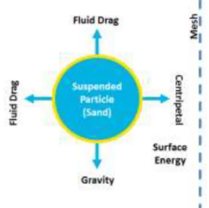
FILTRATION THEORY
To design a reliable, low-cost, low-power filter, different filtration systems were investigated. Techniques for filtering inorganic particles from water differentiate based on the particle size and the scale of operations. In the case of drip irrigation systems, cost and power constraints prevent complex designs or the use of chemical additives like surfactants. The feasibility of
three methods was considered: (1) separation via centrifugal action, (2) settling due to gravitational forces, and (3) physical separation using a screen or porous media. The physics that govern these options are illustrated in Figure 2.
FIGURE 2: BODY FORCES AND MECHANICAL BARRIERS USED TO SEPARATE SUSPENDED PARTICLES FROM
WATER.
Centrifugal filtration operates by flowing unfiltered water around a central axis during which centripetal forces move dense particles outward to the edges of the container. These particles can be collected in a sand trap and removed from the water body. Although well-established, this method generally requires input work and is very sensitive to flow rates and geometries. Creating a drip irrigation adaptation of this filtration strategy was therefore not pursued.
Settling tanks allow dense particles to gravitationally settle in a stagnate tank. The particles are then collected in a catch basin and the flow is sourced from the top of the tank. To be effective, this technique requires stagnant or very slow moving laminar fluid which is well-suited for large scale operations. Unfortunately, large settling tanks for drip irrigation can cost over 1000 USD and are therefore prohibitively expensive.
Filtration through a porous media or mesh screen geometrically separates particles from the flowing fluid in a drip irrigation system. As the flow passes through the screen, all particles above a critical size are physically blocked by the screen and removed from the flow.
Pressure drop across a porous media is governed by Darcy’s Law in which the change in pressure ΔP (Pa) across the porous media can be expressed as
(1) where is the volumetric flow rate (m3/s), A is effective cross-sectional area (m2) of the porous media, µ is the viscosity (Pa·s) of the fluid through the medium, L is the thickness (m) of the medium, and k is the permeability (m2) of the porous medium. Hydraulic resistance across a mesh filter increases via two mechanisms.
First, accumulated particles on the filter surface create additional barriers through which the fluid flows and therefore reduce the effective permeability of the surface (k/L). Assuming the accumulated particles coat the filter evenly, the effective permeability of a cylindrical filtration system can be found by:
(2)
where ko is the original permeability of the filter paper, Lo is the
thickness of the filter paper, kacc is the permeability of the
filtered media, Lacc is the thickness of the accumulated layer,
and Vacc is the volume of accumulated filtered media.
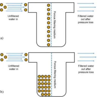
The second mechanism for reducing the flow across a mesh filter occurs when the filtered particles that fall away from the filter surface volumetrically fill the space between the filter and its housing. This accumulated material is significantly less permeable and therefore reduces the effective available surface area of the filter (A). This mechanism asymptotically decreases flow as particulate matter accumulates until the filter is volumetrically filled and thus clogged. The reduction of effective cross-sectional area in a typical cylindrical mesh filter is simply found by
(3) where Ao is the original effective cross-sectional area of the
filter, Vfilter is the available capacity or volume between the
housing and the filter to contain filtered particles, w is the length of the filter/housing, Dhousing is the diameter of the
housing, and Dfilter is the effective diameter of the filter. These
two mechanisms for increasing the hydraulic resistance of the filter are found in Figure 3.
DRIP FILTER DESIGN STRATEGY
Simple cylindrical mesh filters are presently used in drip irrigation systems, as shown in Figure 4. For the high levels of particulate matter in Zambian surface water, the filter’s housing quickly fills with particles and thus clogs. This requires unrealistically high level of maintenance and handling the filter many times which is cumbersome for the user and often leads to the abandonment of the system.
To overcome the maintenance challenges of the existing cylindrical filter system, the following three design changes were investigated. First, high volume pleated cartridge filters were investigated as a replacement to the straight-walled cylindrical filters. Second, the housing was redesigned such that the filter did not have to be removed with every cleaning, thus easing the operation. Third, the filter housing volume was increased to allow for higher volumes of accumulated particles. These three design changes simplified the filter housing design which could be manufactured via inexpensive blow-molding.
a)
b)
FIGURE 3: THE TWO MECHANISMS THAT CAN CREATE HYDRAULIC RESISTANCE. A) IN MECHANISM 1, PARTICLES EVENLY COAT THE FILTER SURFACE, CREATING A THICKER, LESS PERMEABLE MEDIUM. B) IN
MECHANISM 2, PARTICLES SETTLE IN THE FILTER HOUSING, REDUCING THE EFFECTIVE FILTER AREA THAT
IS EXPOSED TO FLOW.
FIGURE 4: A TYPICAL MESH FILTER CURRENTLY USED IN DRIP IRRIGATION SYSTEMS.
Cartridge Filter
Compared to a cylindrical filter, a pleated cartridge filter has reduced hydraulic losses for two reasons. First, the increased surface area of the folded pleats reduces the pressure drop across the filter as governed by equation 1. Secondly the additional available volume within the pleats enables more particulates to deposit away from the walls of the filter, as shown in Figure 5b.
FIGURE 5: EXAMPLE OF PLEATED CARTRIDGE FILTERS. A) A TYPICAL CARTRIDGE FILTER USED FOR HIGH VOLUME FLOWS. B) THE FOLDED PLEATS CREATE ADDITIONAL SPACE IN WHICH PARTICULATES CAN
SETTLE.
For these benefits, pleated cartridge filters are already used in industrial water treatment and in both residential and commercial swimming pools. With advertised lifetimes of 2-8 years [15], cartridge filters are already available for the desired flow rates for a 1000 m2 drip irrigation system (≈ 25 L/min) with an acceptable pressure loss (<0.05 bar). This work will characterize the advantage of a pleated cartridge filter over the conventional cylindrical mesh filter and improve upon the clogging mechanisms inherent to both systems.
Internally Supported Filter
A new housing that supports and seals the filter from the top housing was designed. As shown in Figure 6, this concept supported and sealed the cartridge filter with a central rod and rubber plug suspended from the top housing. This plug could be tightened against the filter with a wing nut. This simple mechanism allowed the bottom casing to be extended below the base of the filter as shown in the following section. Supporting the cartridge filter from the center allows for easy cleaning because only the bottom housing needs to be removed when the filter is washed. Since the filter remains attached to the top of the housing its seals are not released, reducing the risk of faulty installation during regular maintenance.
Extended Housing
A pleated cartridge filter system could avoid the asymptotic pressure rise described by equation 3 if the filtered particles could settle away from the filter when the flow ceased. A simple way to do this would be to extend the housing below the filter. Unfortunately, this is not possible with off-the-shelf filter housing because the filter’s bottom o-ring is designed to seal to the bottom housing. However, with an internally supported filter, extending the housing is possible. As shown in Figure 8, the bottom housing was extended to provide more room for filtered particles.
FIGURE 6: A) INTERNAL THREADED ROD AND PLUG ASSEMBLY FOR SUPPORTING THE CARTRIDGE FILTER B) NEWLY SUPPORTED CARTRIDGE FILTER WITH EXTENDED
HOUSING.
EXPERIMENTAL SETUP
To measure how these design elements affect filter performance in the context of a drip irrigation system, a scale test setup was constructed as shown in Figure 7a. The apparatus consisted of a 15 gallon tank that was elevated to 2 m and connected to a 1” flexible hose serving as the main line. The main line was connected to the inlet side of the filter housing and the outlet of the housing connected to a reservoir tank containing a sump-pump which sent water through the pump line back to the elevated tank. An off-the-shelf 50 µm, high-capacity polyester cartridge filter with a height of 10” was used (McMaster-Carr product #6657T25).
As shown in Figure 7b, the pressure drop across the filter was measured using two Omega PX309-015G5V transducers which have a range of 0-15 psi and an accuracy of 0.25% [16]. The data was recorded using a Measurement Computing USB-201 DAQ at a sampling rate of 5 Hz. Flow rate was measured by timing how long it takes for 12L of water to flow out of the system.
TEST PROCEDURE
To simulate the filter’s performance with Zambian source water, fine sand (50-250 µm) consistent with Zambian soil was added incrementally into the test setup’s source water. This media was added while maintaining the flow across the filter. The pressure drop across the filter and system flow rate was then measured under two different conditions. The first measurement was taken while the flow was maintained across the filter after the particulates were added to the source water. The second measurement was taken after the flow has been stopped for several minutes and then restarted. This is representative of Zambian subsistence farmers finishing their daily watering process and stopping the flow at the end of each day, and then activating the systems again the following day. In each case, the pressure drop measurement was averaged over a
1 minute period. The increments of sand were added until the pressure drop exceeded an acceptable level (0.9-1.0 bar).
The flow rate through the system was initially 24-25 L/min which is consistent with the required flow rate for a 1000 m2 field requiring 6200 L per day operating for 4 hours a day. As the pressure drop across filter increased, the flow rate decreased.
a)
b)
FIGURE 7: A) EXPERIMENTAL DRIP IRRIGATION SETUP. B) EXPERIMENTAL FILTER ASSEMBLY WITH DUAL
PRESSURE TRANSDUCERS. UNFILTERED WATER FLOWED FROM THE LEFT, AND THE PRESSURE TRANSDUCERS MEASURE PRESSURE BEFORE AND
The procedure was run for three filter configurations: (1) the cartridge filter was used in the conventional configuration (Figure 8a), (2) the cartridge filter was wrapped with a 50 µm polyester filter paper sheet such that the filter became a pure cylinder similar to the current filter technology (Figure 8b), and (3) the cartridge filter was placed into an oversized housing such that the lower half of the housing was empty (Figure 8c).
FIGURE 8: A) CONVENTIONAL PLEATED FILTER CONFIGURATION. B) CYLINDRICAL, NON-PLEATED
CONFIGURATION INSIDE HOUSING.
C) CONVENTIONAL PLEATED CONFIGURATION IN AN EXTENDED HOUSING.
PRESSURE LOSS BEHAVIORS
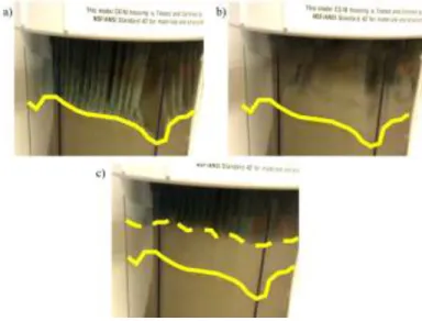
For each of the first two filter configurations (Figures 8a and 8b), the head loss across the filter increased by the mechanisms described in equations 2 and 3 after each increment of sand was added. As shown in the time elapsed images in Figure 9, sand particles pressed on to the surface of the filter while there was still flow through the filter. As a result, the effective permeability of the filter surface decreased as described by equation 2. When the flow was ceased, the force holding the particles to the surface abated and the filtered particles settled to the bottom of the housing due to gravity. When the flow was restarted, the system exhibited a post-settling behavior in which the pressure loss across the filter was reduced as compared to the prior continuous operation, as described by equation 3.
The tendency of filtered particles to coat the filter and then settle to the bottom of the housing resulted in the zigzag pressure data of Figure 10. In this data, the peaks of each filter curve correspond to measurements taken after the particles were introduced into the filter but before the flow had not stopped. The drops, or troughs, in the data correspond to measurements taken after the flow had ceased, the particles had settled to the bottom of the housing, and the flow was recommenced.
FIGURE 9: TIME LAPSE OF SETTLING BEHAVIOR WITHIN FILTER HOUSING. A) AS WATER FLOWS THROUGH THE FILTER, PARTICULATES COAT THE AVAILABLE SURFACE
AREA ON THE PLEATS. SOLID LINE OUTLINES INITIAL LEVEL OF PARTICULATE SETTLING. B) REPRESENTATIVE
OF FARMERS TURNING OFF THEIR DRIP IRRIGATION SYSTEM FOR THE DAY, THE FLOW IS SOPPED AND THE PARTICLES RELEASE FROM THE PLEATS AND BEGIN TO
SETTLE. C) DOTTED LINE INDICATES NEW LEVEL OF SETTLED PARTICULATES.
FIGURE 10: PRESSURE DATA VISUALIZATION OF PRESSURE LOSS BEHAVIOR DURING CONTINUOUS FLOW
AND DISCONTINUED FLOW.
EXPERIMENTAL RESULTS
The results in Figure 11 confirm three important concepts. First, the pressure drop across the pleated cartridge filter resulting from the effective permeability of the coated particles (mechanism 1) was lower than that of the cylindrical wrap filter for a given amount of accumulated particles. The pressure loss of the pleated filter only began to approach that of the cylindrical wrap filter after over 1500 grams of sand was loaded.
Second, the increase in pressure drop exhibited by the cylindrical wrap filter occurred much faster relative to the amount of particles that had been added to the filter (mechanism 2). This was the result of the available volume within the housing in which the sand could settle. With 500 grams of particles loaded around the cylindrical wrap filter, the sand level nearly reached the top of the housing, effectively blocking the usable filter area. In the case of the cartridge filter, the sand was able to accumulate within the pleats of the filter enabling much more sand to build up in the housing without covering the entire filter surface. 2500 g of filtered particles were needed to fill the housing
Third, the extended housing configuration described in Figure 8c allowed filtered particles to settle below the filter and therefore not cover the filter. Without sand accumulating around the filter, the comparatively low pressure loss across the filter in the extended housing was maintained at its initial level throughout successive sand loading (Figure 11).
FIGURE 11: MEASURED PRESSURE DROP ACROSS THE FILTERS AS SAND WAS ACCUMULATED AS MEASURED BY
THE DUAL PRESSURE TRANSDUCERS.
BLOW-MOLD HOUSING DESIGN
Decoupling the support and sealing of the cartridge filter from the external housing not only displayed the performance required of a low-pressure filter but also provided an additional opportunity to reduce the cost of the filter for rural drip irrigation systems. The off-the-shelf cartridge filter housing is a quarter inch thick, complex, plastic injection molded piece seals to the top housing via large structural threads and an O-ring.
Because the bottom housing no longer has to serve as a structural element when the filter is supported by a central rod, the bottom housing thickness can be reduced that of a typical coke bottle. This results in less plastic needed (only $0.10 raw material needed), and, more importantly, this design can be manufactured via blow-molding. Blow molding equipment is typically used to make plastic bottles and is more readily available in developing world economies than plastic injection machines. Furthermore, blow molding is both less expensive and capital intensive. As shown in Figure 12a, the external
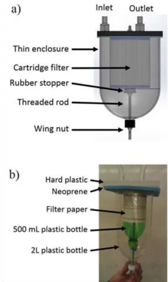
housing can simply be a thin blow-molded container that is comparable to a plastic bottle. This container can be supported by the already existing threaded rod that now supports the cartridge filter (Figure 10b). As shown in the CAD model (Figure 12a), the tensioned threaded rod can compress the external housing against the top structure and gasket and can therefore eliminate the need for the complex threaded injected molding piece. There are other mechanisms for forming this top seal, and the authors recommend further investigation is needed to identify the optimal sealing strategy.
FIGURE 12: A) THE CAD AND B) CONCEPT PROTOTYPE FOR AN ALTERNATIVE HOUSING GEOMETRY THAT FIXTURES AND SEALS BOTH THE FILTER AND EXTERNAL
HOUSING VIA A CENTER MOUNTED THREADED ROD.
Another design feature of this low-cost prototype was the introduction of a plug in the bottom housing. This plug can simply be removed to allow for regular draining of filter media without removing the bottom housing. This will further reduce the number of parts that have to be handled for regular cleaning.
It is recommended that further work is done to optimize this plug design.
To test the proposed design, a low-cost prototype was constructed using a 2 L plastic bottle instead of the standard enclosure and a perforated 500 mL plastic bottle wrapped in filter paper to represent the cartridge filter (Figure 12b). When the low-cost plastic bottle prototype was loaded with sand, particle behavior during continuous operation and settling were qualitatively similar to those observed in the off-the-shelf filter. This study is not advocating for repurposing plastic bottles for filters. Rather, the goal is to demonstrate that inexpensive materials and manufacturing methods could be employed to deliver the same performance of an off-the-shelf expensive housing system. This study hopes that this simple design can be used to manufacture reliable, easily cleaned cartridge filter systems for less than $1.
CONCLUSION
To increase the reliability and usability of a drip irrigation system, clogging was investigated and an alternative low-cost, robust alternative filtration system was proposed. To reduce the pressure drop across the filter, the typical cylinder filter was abandoned for a pleated cartridge filter which exhibits more effective surface area and more volume for filtered particles to settle. The experimental setup showed that the pleated cartridge filter both had a lower starting resistance to flow and could hold more sand before clogging.
An alternative filter housing design was proposed that allowed for the settling sand to reside away from the cartridge filter so as to prevent clogging. This design sealed and supported the cartridge filter via a threaded rod and rubber plug supported from the top housing. With this simple apparatus, the housing could be extended beyond the base of the cartridge filter to extend the maintenance life of the system.
The rod supported cartridge filter design further enabled a lower cost filtration system. The present off-the-shelf external housing is a large structural piece that becomes irrelevant given the support of the rod/plug assembly. Ergo, a low-cost alternative housing that is made via blow molding was designed in CAD, and a first prototype was made from 2 liter plastic bottles. This concept prototype demonstrated that an inexpensive housing along with a cartridge filter could yield a low-cost and reliable drip irrigation filtration system.
Further work is needed to implement the discussed work in the field. First, this paper recommends that the CAD design be further developed with input from iDE and other organizations in the space. Second, it is necessary to find appropriate gasket material that can endure the 5-10 years of system life. Third, the lifespan of off-the-shelf cartridge filters should be tested with site-specific water sources to ensure their performance is consistent with lab performance.
ACKNOWLEDGMENTS
This work was sponsored by MIT Tata Center for Technology and Design and the MIT Department of Mechanical
Engineering. This work was part of Professor Amos Winter’s Global Engineering Course in the fall semester of 2013. The authors would like to especially thank iDE (International Development Enterprises) as the partner for the project.
REFERENCES
[1] Postel, S., 2000, “Redisigning Irrigated Agriculture,” State of the World 2000, L. Starke eds. W.W. Norton & Company, New York, NY, pp. 39–58.
[2] Maisiri, N., Senzanje, A., Rockstrom, J., and Twomlow, S.J., 2005, “On Farm Evaluation of the Effect of Low Cost Drip Irrigation on Water and Crop Productivity Compared to Conventional Surface Irrigation System,” Physics and Chemistry of the Earth, 30, pp. 783-791.
[3] von Westarp, S., Chieng, S., and Schreier, H., 2003, “A Comparison Between Low-Cost Drip Irrigation, Conventional Drip Irrigation, and Hand Watering in Nepal,” Agricultural Water Management, 64, pp. 143-160. [4] Sijali, I.V., 2001, “Drip Irrigation: Options for Smallholder
Farmers in Eastern and Southern Africa,” Technical handbook no. 24, Sida Regional Land Management Unit, Nairobi, Kenya.
[5] Frenken, K., 2005, “Country Profile: Zambia,” Irrigation in Africa in Figures: AQUASTAT Survey - 2005, FAO Water Report no. 29, Food and Agriculture Organization of the United Nations, Rome, Italy.
[6] Stoddard, E. and Mfula, C., 2013, “Drought Threatens Small-Scale Zambian Maize Farmers,” Reuters, from
http://www.reuters.com/article/2013/11/19/us-zambia-drought-idUSBRE9AI0ET20131119 (accessed December
3, 2013).
[7] Zambia, Republic of, 2007, “Fifth National Development Plan,” Poverty Reduction Strategy Papers, IMF Country Report no. 07/276, International Monetary Fund, Washington, D.C.
[8] Frenken, K., 2013, “Zambia: UN-Water Country Brief,” Food and Agriculture Organization of the United Nations. [9] Polak, P., Nanes, B., and Adhikari, D., 1997, “A Low Cost
Drip Irrigation System for Small Farmers in Developing Countries,” Journal of the American Water Resources Association, 33(1), pp. 119-124.
[10] Tuabu, O.K., 2012, “The Innovation of Low-Cost Drip Irrigation Technology in Zambia: A Study of the Development of Drip By International Development Enterprises and Smallholder Farmers,” MSc. Thesis, Wageningen University, Wageningen, Netherlands.
[11] Nanes, B.., 2013, International Development Enterprises, private communication.
[12] Nakayama, F.S., and Bucks D.A., 1991, “Water Quality in Drip/Trickle Irrigation: A Review,” Irrigation Science, 12, pp. 187-192.
[13] Ravina, I., Paz, E., Sofer, Z., Marcu, A., Shisha, A., and Sagi G., 1992, “Control of Emitter Clogging in Drip Irrigation With Reclaimed Wastewater,” Irrigation Science,
[14] Capra, A., and Scicolone B., 2004, “Emitter and Filter Tests for Wastewater Reuse By Drip Irrigation,” 2004, Agricultural and Water Management, 68, 135-149.
[15] National Pool Design FAQs. National Pool Design from
http://www.nationalpooldesign.com/faqs.html (accessed
November 21, 2013).
[16] PX309/PX319/PX329/PX359 Series Pressure Transducer General Information Page. Omega Engineering Inc. from
http://www.omega.com/pptst/PX309.html (accessed