HAL Id: hal-02416292
https://hal.archives-ouvertes.fr/hal-02416292
Submitted on 17 Dec 2019
HAL is a multi-disciplinary open access
archive for the deposit and dissemination of
sci-entific research documents, whether they are
pub-lished or not. The documents may come from
teaching and research institutions in France or
abroad, or from public or private research centers.
L’archive ouverte pluridisciplinaire HAL, est
destinée au dépôt et à la diffusion de documents
scientifiques de niveau recherche, publiés ou non,
émanant des établissements d’enseignement et de
recherche français ou étrangers, des laboratoires
publics ou privés.
ASTRID an innovative control rod system to manage
reactivity
B. Fontaine, P. Sciora, M. Vanier, C. Venard
To cite this version:
B. Fontaine, P. Sciora, M. Vanier, C. Venard. ASTRID an innovative control rod system to manage
reactivity. International Congress on Advances in Nuclear Power Plants (ICAPP - 2016), Apr 2016,
San Francisco, United States. �hal-02416292�
ASTRID : an innovative control rod system to manage reactivity
B. FONTAINE, P. SCIORA, M. VANIER, C. VENARD
CEA, DEN
DER/SPRC, Cadarache, F-13108 Cedex Saint-Paul-lez-Durance, France Tel:+33642254829, Email:[email protected]
An innovative control rod system which may be applied to the French project ASTRID is presented. All the rods participate to power management and safety shut-down. Comparatively to traditional systems, the gains of this architecture in terms of safety margins (after shutdown, in case of incident during refueling operation and consequences of control rod withdrawal) are noticeable and allows reducing the overall number of control rods.
A possible way of implementing control rods for automatic power regulation with a constant efficiency during cycle is also described.
I.INTRODUCTION
Contrarily to the pressurized water reactors which have two independent systems to control the reactivity of the core (control rods and soluble boron), the fast sodium-cooled reactors can only count on control rods. Consequently, control rods have to fulfill a wide range of functions in reactivity management, such as reactor power rise from criticality to nominal power, burn-up compensation, fine piloting of power map, efficient shutdown capacity and guaranty of subcriticality during fuel handling periods.
To do so, a complete architecture taking into account including absorbing devices, motion systems, control and instrumentation has to be developed. This architecture should be designed with a defense-in-depth approach based on redundancy, diversity and independence in order to minimize both failure frequencies and consequences. Moreover the design should limit the complexity of the system with the aim of minimizing the impact on the reactor cost.
This paper presents the control system studied for ASTRID reactor at the end of conceptual design phase and shows what are the expected gains in terms of performances comparatively to past projects.
II.REACTIVITY MANAGEMENT NEEDS
The control rod system (CRS) of ASTRID has to ensure the following functions:
-allowing to reach criticality and power rise up to nominal power (1600 pcm1),
-compensating reactivity swing due to fuel burn-up during one cycle (1600 pcm),
-adjusting power level to electrical grid demand (120 pcm),
-fine piloting of core power map and hot spots (200 pcm) ,
-ensuring reactor shutdown in normal and incidental situations,
-maintaining reactor subcritical during refueling and maintenance periods.
Another important need required for ASTRID core design is to insert enough negative reactivity in case of cooling accident to avoid sodium boiling [Ref. 1]. As the core design chosen for the basic design phase is based on CFV concept [Ref. 2], the core can provide a large part of these needs thanks to its favorable natural behavior (neutron feedback). However, the integration of overall uncertainties showed that the margin is insufficient face to a robust demonstration. To ensure larger margins, the natural behavior of the core has to be completed by complementary safety devices able to insert -400 pcm in case of ULOF and ULOSSP.
As we will see in the next chapter, the worth of CRS is mainly constrained by the needs of subcriticality during refueling periods and those required for reactor shutdown. CRS has to provide a sufficient antireactivity to ensure a subcritical state of the core, in spite of anomalies, incidents and errors which may occur in phase of fuel handling for example. The reactor is then in a standard cold isothermal state (named CIS, typically 180°C) .
Concerning shutdown needs, CRS has to guaranty core subcriticality for a temperature state acceptable with the behaviour of the structures and allowing reactor operations to reach a long time safe state. In that case, two shutdown states are considered: CIS previously defined and neutron smothering state (NSS) corresponding to an isothermal temperature for which the core is maintained subcritical thanks to the thermal negative feedbacks (typically 450°C).
Another point to consider is the kinetics of power decrease after a SCRAM which has to be fast enough. A
sensitive study shows that under -7 $ of antireactivity insertion the gains on power decrease are limited (see Fig. 1).
Fig. 1. kinetics of reactivity insertion during SCRAM To fully evaluate the needs in antireactivity insertion, all the situations requiring the intervention of the CRS have to be listed. Those which are not covered have to be practically eliminated by core or rector design.
For ASTRID, the main accidents of reactivity considered during shutdown state are partial draining of the primary sodium and radial core compaction possibly worsened by local draining in core regions with positive sodium worth.
Fuel handling errors are considered too. The first one is fresh fuel element loading instead of control rod. The second one is unloading of two control rods.
Then, in a defense-in-depth approach, for each scenario where the totality or only a part of the CRS is involved, the single failure criterion is applied, considering conservatively that the failed device or system is the one with the higher worth. Moreover, the function has to be assessed taking into account uncertainties which come from:
-core reactivity estimation,
-control rod worth, including 10B consumption (Ref. 3 ,4),
-reactivity swing due to burn-up, including neptunium effect
-neutron feedback effects -delayed neutron fraction…
III.ADDITIONAL CONSTRAINTS
Additionally to the reactivity needs, the CRS design should meet constraints coming from safety consideration and cost savings. Among them we can quote:
-lessons learned from previous fast-reactors operations,
-minimizing of absorber subassembly length, -extension of residence time,
-reduction of the total number of absorbing subassemblies,
-keeping the enriched absorber material requirement as low as possible.
Regarding safety aspects, one important point is to prevent consequences of an inadvertent control rod withdrawal (ICRW). Even if active or passive systems can be implemented to reduce such event probability and limit consequences, a CRS which helps to eliminate risk of fuel melting in case of ICRW is highly preferable.
IV.CONTROL ROD ARCHITECTURE IV.A. Past projects architecture
In the previous French SFR projects developed in 80’s and 90’s, the control rod architecture was based on two different kinds of absorbing elements.
The first one was dedicated to reactor operating (power management, burnup compensation …) but also participates for shutdown needs. The absorbing elements were named respectively SCP and CSD in SUPERPHENIX and EFR projects.
Complementary to the first type, a second kind of less numerous elements was used only for SCRAM and shutdown states. As they were not used for power management, they were completely withdrawn during operation. The elements were named SAC and DSD in SUPERPHENIX and EFR projects.
In the EFR project, all the DSD and CSD elements were gathered in two redundant shutdown groups (RG1 and RG2) as presented in Fig 2.
Three independent systems existed to perform the shutdown function: SD1 and SD2 (i.e. shutdown #1 et #2) with gravity fall and PPS (i.e. plant protection system) with motorized insertion of control rods. SD1 and SD2 were linked by optical device allowing the shutdown of
the second system when the first one was actuated. Fig. 2. EFR shutdown system
IV.B. Proposition of an innovative architecture
The first motivation for a new CRS is to limit consequences of an ICRW accident. As the reactivity swing due to burnup is compensated by progressive control rod withdrawal, the more the inserted control rods are, more serious are the consequences of one ICRW accident. Thus, for a fixed total number of control rods, it is preferable to share reactivity needs on the highest number of control rods.
The other motivation is to have a better sharing out between rods which participate to operation and to shutdown needs, in order to gain margin for safety criteria and improve the map power management.
An innovative CRS architecture was studied for ASTRID project. It is named RID architecture and mainly relies on absorbing elements named RBC and RBD (Ref. 5).
RBC is a control element dedicated to reactor operation and shutdown. In case of gravity chute, the absorbing rods fall with its driving line after decoupling the electromagnet located in gas, above the sodium level.
RBD is a diversified control element used for reactor operation and shutdown too, contrarily to DSD only dedicated to safety function. As a major chosen design option, disconnection in case of scram between the RBD rod and its drive mechanism would occur via an in-sodium electromagnet that does not extend beyond the absorber subassembly lifting head. This constitutes a diversification against common mode failure of insertion of RBC rods into the subassemblies that makes it possible to guarantee safe core shutdown in case of significant deformation of the reactor block that would be likely to block the RBC mobile rods in their wrappers.
During normal operation, both RBC and RBD are partially withdrawn and used in a same way to manage power level, compensate burnup reactivity swing and adjust power map.
As for EFR project, RBC and RBD are gathered in two independent groups (GD1 and GD2) connected to independent shutdown systems.
The complementary reactivity needs required for core cooling accident are covered by additional elements. One of the most promising options is hydraulic actuated system, named RBH (Ref. 6, 7). As RBC and RBD, this concept consists of a mobile absorber rod in a stationary hexagonal wrapper tube identical to the one of fuel subassemblies. At the normal operation condition, the absorber rod is hydraulically suspended above the core by the upward flow of the sodium coolant. Should a LOF event and the associated drop in flow rate occur, this upward force could become insufficient, making the rod drop hydraulically actuated and allowing the absorber material to insert by gravity into the active core region.
Because of its efficiency and its large feedback in past reactors, boron carbide is the favored absorber
material for control rods in fast reactors. Considering the significant experience accumulated during Phénix irradiations, the choice for the absorber element of all kind of control assemblies (RBC, RBD and RBH) is a classical pin design vented by porous plugs, with a high-density boron carbide pellet. A large pellet clad gap accommodates the irradiation-induced swelling and the deformation in order to delay as much as possible pellet clad mechanical interaction (PCMI). The absorber pellet is bound with a sodium layer to improve the initial gap conductance. The target lifetime for control rods is the same residence time as the fuel element, that is to say, 1440 EFPD. In order to reach such a residence time, the absorber pellet stack is enclosed in a shroud to prevent fragment relocation at an early stage of the irradiation that would be followed by a premature PCMI. Moreover, the capture rates at the follower-absorber interface are minimized by adjusting two axial enrichment zones in RBC and RBD absorber system. As these element are partially inserted in core during operation, the lower part having the highest neutron exposure is made of natural boron carbide (45 cm) while the upper part (40 cm) can afford the utilization of enriched B4C (48% 10B). As the
RBH are kept withdrawn above the fissile zone during reactor operation, they are less exposed to the neutron flux, and the RBH absorber consists of a single axial zone of enriched B4C (48%
10
B).
IV.C. Comparison of EFR and RID architectures
To analyze the benefits of a RID architecture, a comparison of RID and EFR features is performed on a ASTRID-like core (see Fig. 3). In such a core, 21 positions are dedicated to control rod elements. Among them 3 are reserved for RBH.
In the RID option, RBC and RBD are both used for power management and shutdown needs. The share among the 18 positions left is 9 RBC and 9 RBD. The shutdown groups GD1 and GD2 are respectively constituted of 5 RBC + 4 RBD and 4 RBC + 5 RBD. The total worth of RBC+RBD is 6057 pcm.
For the EFR option, the share between control rods are 12 RBC which participate to power management and shutdown needs (same role than CSD in EFR project), and 6 RBS which are normally completely withdrawn and only used for shutdowns (as DSD in EFR project). In that case GD1 and GD2 are both constituted of 6 RBC + 3 RBS. As RBS are withdrawn at nominal power, they are less exposed than RBD to neutron flux and allow to use only enriched B4C (48% 10B). The total worth of
Fig. 3. Positions of RBC, RBD and RBS in RID and EFR architecture
IV.C.1. Subcriticality reserve
In table I are compared the reactivity margins for EFR and RID architecture for subcriticality needs during shutdown states. For sodium draining and core compaction accident during refueling where all control rod groups (GD1 and GD2) are normally inserted, the analysis takes into account the fact that one control rod may be unloaded from the core. In that case RID and EFR architecture provide respectively 1117 pcm and 1309 pcm against the potential reactivity insertion, which are both very large values. For the large earthquake scenario during refueling the analysis considers core compaction worsened with local sodium draining due to numerous pin failures. In that case both RID and EFR architectures provide large values of antireactivity (resp. 1484 and 1676 pcm) to avoid prompt criticality.
In the same way, fuel handling errors are covered with large margins with both RID and EFR options. Taking into account that RBH are inserted during refueling, the replacement of one control rod by one fresh fuel makes the core subcritical respectively less than -518 and -584 pcm. The unloading of two control rods is covered with margin larger than 940 pcm.
We can see that both EFR and RID options offer large margins in subcriticality for postulated accidents or errors during refueling with a small advantage for EFR option due to better worth of RBS than RBD.
Another criterion to consider is the subcriticality reserve needed to perform a criticality approach for startup operation. This procedure consists in a progressive extraction of control rods to start the nuclear reaction from a subcritical state (typically -800 pcm) up to criticality. For the EFR option, this approach is done only with RBC and should be performed after the total withdrawal of all the RBS. In that case, as we can see in table I the subcriticality only brought by RBC is not enough to meet the criterion (549 pcm are missing). With RID option, as the approach is done by extracting
simultaneously RBC and RBD until criticality, the criterion can be reached with a large margin (1120 pcm).
TABLE I. Subcriticality reserve margins
Subcriticality reserve Margins (pcm) RID EFR Sodium draining (NaD)
during fuel handling
GD1+GD2-1CR + NaD CIS 1117-NaD 1309-NaD Core compaction (CoC)
during fuel handling
GD1+GD2-1CR + CoC CIS 1117-CoC 1309-CoC Large Earthquake (LaE)
during fuel handling
GD1+GD2-1CR + LaE-1$ CIS 1484-LaE 1676-LaE Fuel handling error :
Fuel instead of CR
GD1+GD2+RBH -1CR+1FuelCIS
518 584 Fuel handling error :
2 CR extracted GD1+GD2+RBH -2CRCIS 940 1134 Criticality approach with RBS withdrawn RBC+RBD+800pcm CIS RBC+800 pcm CIS 1120 -549
IV.C.2. Shutdown needs
The table II presents margins relative to shutdown criteria, considering partial failure of CRS. The failure of one control rod chute allows to reach cold state (CIS) with large magins with both options (>1100 pcm). The failure of one group GD1/GD2 (worsened by the failure of one control rod in the remaining group) is acceptable with margins ranging between 123 and 224 pcm, with an advantage to EFR option.
The failure of one type (RBC/RBD or RBC/RBS), worsened by the failure of one control rod in the remaining type, is the case where the margins are the smaller. Whereas with EFR option the margins are very small (77 pcm), some additional margins can be found with RID option (125 pcm).
Regarding SCRAM kinetics the RID and EFR options allow to bring more than 7 $, with margins of 2.2 $ and 3.1$ respectively.
TABLE II. Shutdown margins
Shutdown criteria Margins (pcm) RID EFR Failure of one CR GD1+GD2-1CR CIS 1117 1309 Failure of one group
and one CR in the other group
GD1-1CRNSS 170 224 GD2-1CRNSS 123 212 Failure of CR type
and one CR in the other type RBC-1CRNSS 336 596 RBD-1CRNSS RBS-1CRNSS 165 77 SCRAM kinetics RBC+RBD > 7 $ RBC+RBS > 7 $ 2.2 $ 3.1 $
IV.C.3. Inadvertent control rod withdrawal
To prevent severe accident, no fuel melting is aimed in the case of total withdrawal of the most penalizing control rod. For any fuel assembly at ith position in the
core, the final linear power PLINCRW reached after an
unprotected control rod withdrawal can be expressed as : PLINCRW = PLIN0.(1+ki.).(1+b0.)
where PLIN0, ki, and b0 represent respectively the initial
linear power, the normalized power map deviation at ith position and the power raise due to unit reactivity insertion, and the reactivity insertion generated by the control rod withdrawal.
As PLINCRW has to be lower than linear power
leading to fuel melting PLINmelt, taking into account
uncertainties, we can determine the maximal admissible linear power PLIN0
max at nominal power : ) 1 )( 1 ( 0 max 0 b k PLIN PLIN i melt
In table III are presented the values obtained for RID and EFR options. As all the 18 control rods participate to power operation in RID option, the reactivity raised by a CRW is much smaller than in the EFR option where only 12 RBC are involved (98 pcm vs 141 pcm). Moreover, as the repartition of control rods is tighter, the power deviation caused by CRW in the RID option is less penalizing than in the EFR (0.139 vs 0.181 %/pcm). Finally whereas RID option offers positive margin on linear power (+4%), the EFR option does not allow to meet fuel melting criterion.
TABLE III. CRW consequences RID EFR
(pcm) 98 141 ki (%/pcm) 0.139 0.181
Margin on PLIN0 +4% -8%
Fuel melting no yes
IV.C.4. Conclusion
With a larger number of control rod involved in reactor operation and not only dedicated to shutdown needs, the RID option offers larger margins than EFR option on the most penalizing criteria such as failure of one CR type, antireactivity reserve for subcritical approach and prevention of control rod withdrawal consequences. Thus the ASTRID project decided to choose RID architecture as reference for the core basic design.
The figure 4 presents the position of fuel assemblies and control rods in ASTRID core, at the end of the conceptual design phase. Yellow and red hexagons represent respectively internal and external core fuel assemblies. White ones are diluent assemblies. Nine RBC and nine RBD are regularly distributed in the internal core. Three RBH are positioned at mid-diameter of the internal core, with a 120° symmetry.
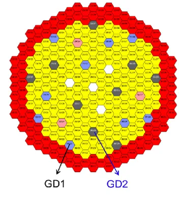
The figure 5 shows the equitable repartition of RBC and RBD in groups GD1 and GD2. As RBH do not participate to normal shutdown system, they are not included in these groups.
Fig. 4. Positions of RBC, RBD and RBH in ASTRID core
Fig. 5. Attributions of RBC and RBD in shutdowns groups GD1 and GD2
V.POWER REGULATION V.A. Needs and design criteria
One of the missions of nuclear power plants in France is to participate to the grid stability by regulating electrical production consistently to the demand. As ASTRID has to be representative of the future GEN-IV nuclear power plants that will be connected to the grid, a demonstration of power regulation is planned to be performed.
At the conceptual design phase of ASTRID project, the needs for power adjustment range are estimated close to ±7%. For the feasibility studies, the needs are voluntarily extended up to ±10%, i.e the reactor should adjust its thermal power in the range 80% to 100% of nominal power (1500 MWth).
To do so, the control rod architecture should integrate absorbing elements able to adjust automatically the nuclear power. As the total number of control rod is limited, some RBC have to play the role of regulating rods. Adjusting power from 80% to 100% requires reactivity needs of 120 pcm which can be split using 3 dedicated RBC in order to minimize power map deformation.
Two main issues have to be considered regarding regulating RBC. The first one concerns safety and the risk of total withdrawal of the 3 regulating RBC in case of regulation failure. The system has to be designed in order to eliminate fuel melting in such an event. The second point concerns the wish of implementing the simplest regulation system, which efficiency is constant during irradiation cycle. As RBC are progressively withdrawn
during cycle to compensate burn-up reactivity loss, the differential worth of one RBC ranges from 0.42 pcm/mm to 0.07 pcm/mm between beginning and end of cycle. To compensate this variation with time, the system may adjust the displacement of regulating rod in order to get the needed reactivity insertion, but as rod speed is constant, it may affect the response time of regulation.
V.B. Application for ASTRID
To implement a power regulating system matching with the needs and criteria above mentioned, an innovative system has been designed. It consists of 3 dedicated RBC which are almost totally withdrawn at 80% nominal power, with a limited course in the upward direction corresponding to 35 pcm for each rod. During cycle, these three rods do not participate to burn-up compensation contrarily to the other RBC and the RBD. The first advantage of this system is a constant efficiency of regulating rods as their axial positions do not move during cycle. The differential worth at 80% nominal power only ranges from 0.72 to 0.8 pcm/mm between beginning and end of cycle;
The second advantage is a limitation of consequences of an accidental regulating rod withdrawal. As the potential reactivity insertion is 110 pcm, the risk of fuel melting can be eliminated.
However, the specific use of 3 RBC for power regulation with high position implies to insert deeper in the core the other RBC and RBD to adjust reactivity. In case of inadvertent control rod withdrawal the potential reactivity insertion increases from 98 pcm to 117 pcm but fuel melting is avoided.
The implementation of regulating rods modifies margins on CRS regarding shutdown criteria. The table IV presents the smallest ones which concern partial failure of CRS shutdown. In the case of one CR type failure, the margin is reduced by 112 pcm but remains positive.
TABLE IV. Impact of regulation
Shutdown criteria
Margins (pcm) With no
regulation With regulation Failure of one group and one
CR in the other group 123 152 Failure of one CR type and
one CR in the other type 165 53
VI.CONCLUSIONS
An innovative control rod system has been defined for ASTRID. In this architecture, all the rods participate at the same time to power management and safety shut-down. Comparatively to traditional systems such as EFR architecture, the gains in terms safety margin (after shut
down or in case of incident during refueling operation) and consequences of control rod withdrawal are noticeable and allows reducing the overall number of control rods.
This architecture is compatible with implementing control rods for automatic power regulation having a constant efficiency during cycle.
REFERENCES
1. C. VENARD et al., “The ASTRID core at the midterm of the conceptual design phase (AVP2)”,
Proc. of ICAPP 2015, paper 11527, Nice, France
(2015)
2. P. SCIORA, et al., “Low void effect core design applied on 2400 MWth SFR reactor” – Proceedings of ICAPP 2011, Nice, France, May 2-5, 2011. 3. D. BLANCHET et al., “Impact of the control rod
consumption on the reactivity control of a SFR break-even core”, Proc. of ICAPP 2012, Chicago, USA (2012)
4. D. BLANCHET et al., “Control Rod Depletion in Sodium-Cooled Fast Reactor: Models and Impact on Reactivity Control”, Nuclear Science and Engineering, 177, 260–274 (2014)
5. I. GUENOT-DELAHAIE et al., “State of the art of the conceptual designs for ASTRID control and shutdown rods”, Proc. FR’13 Conference, Paris, France, , Paper IAEA-CN-199 (2013)
6. I. GUENOT-DELAHAIE et al., “Conceptual design of complementary safety devices for ASTRID”,
Proc. ICAPP 2014, Charlotte, USA, April 6-9 2014,
Paper 14093 (2014)
7. GUÉNOT-DELAHAIE et al., “The innovative RBH complementary safety device for ASTRID to address unprotected loss of flow transients: from design to qualification”, Proc. of ICAPP 2016, paper 16116, San Francisco, USA (2016)