HAL Id: hal-01875403
https://hal.archives-ouvertes.fr/hal-01875403
Submitted on 17 Sep 2018
HAL is a multi-disciplinary open access
archive for the deposit and dissemination of
sci-entific research documents, whether they are
pub-lished or not. The documents may come from
teaching and research institutions in France or
abroad, or from public or private research centers.
L’archive ouverte pluridisciplinaire HAL, est
destinée au dépôt et à la diffusion de documents
scientifiques de niveau recherche, publiés ou non,
émanant des établissements d’enseignement et de
recherche français ou étrangers, des laboratoires
publics ou privés.
Acoustic isolation of disc shape modes using periodic
corrugated plate based phononic crystal
M. Moutaouekkil, A. Talbi, E.H. El Boudouti, Omar Elmazria, B.
Djafari-Rouhani, P. Pernod, O. Bou Matar
To cite this version:
M. Moutaouekkil, A. Talbi, E.H. El Boudouti, Omar Elmazria, B. Djafari-Rouhani, et al.. Acoustic
isolation of disc shape modes using periodic corrugated plate based phononic crystal. Electronics
Letters, IET, 2018, 54 (5), pp.301 - 303. �10.1049/el.2017.4029�. �hal-01875403�
1
Acoustic isolation of disc shape modes
using periodic corrugated plate based
phononic crystal
M. Moutaouekkil1,2, A. Talbi1, E.H. El Boudouti2, O. Elmazria3, B.
Djafari-Rouhani1, P. Pernod1, and O. Bou Matar1
1)Univ. Lille, Centrale Lille, UVHC, ISEN, LIA LICS/LEMAC - IEMN UMR
CNRS 8520, F-59000 Lille, France. E-mail: abdelkrim.talbi@centralelille.fr
2)LPMR, Faculté des Sciences, Université Mohammed I, Oujda, Morocco. 3)Institut Jean Lamour, UMR 7198, Université de Lorraine - CNRS,
Vandoeuvre-les-Nancy, France.
We investigate the properties of highly confined and isolated surface modes in a phononic crystal based on a stripped membrane combined with disc shape thin films deposited on the micro-strip surface. The structure is made of an Aluminum Nitride (AlN) thin film membrane and Gold (Au) for the disc shape thin film. These materials are chosen owing to the strong contrast in their elastic and density properties and to their compatibility with electroacoustic devices technology. An optimal choice of the geometrical parameters of the membrane and the grooves enables us to obtain wide stop-bands frequency. The introduction of disc shape thin films on the grooved surface enables us to introduce nearly flat modes within the band-gap and consequently paves the way to implement advanced design of electroacoustic filters and high performance cavity resonators.
Introduction: The Phononic crystals are created by periodic arrays of
elastic structures displaying a strong contrast in their elastic properties and density. These materials can be arranged into one-dimensional (1D), 2D and 3D structures. The ability to control the propagation of elastic waves with such composite materials has attracted a considerable attention during the last two decades from science and technology points of view [1]. Similarly to photonic crystals, the interest in phononic crystals has been generated by their unique properties such as the formation of band-gaps, near zero group velocity, and anomalous dispersion (negative refraction). These properties make phononic crystals a viable choice for use in vibration and noise reduction applications [2,3] as well as in the design and implementation of components for Radio Frequency Micro-Electro- Mechanical Systems (RF MEMS) including filters, resonators, and advanced signal processing functions [4-12]. The existence of band-gaps in electroacoustic devices combined with phononic structures has been demonstrated both theoretically and experimentally [4-6,9-12]. The control of propagating waves can be achieved by modifying portions of the phononic structure to induce a line or point defect state. The acoustic energy with frequencies in the band gaps may be localized in the defect and therefore the propagation can be engineered. In the case of locally resonant structural unit cells, the phononic crystals can exhibit band-gaps with a lattice constant smaller than the relevant wavelength [8-11,13-16]. The eigen-frequencies of the localized modes generally depend on the precise geometrical properties (such as size or shape) and the composition of the supporting structure. Many authors have studied the defect states in such phononic crystals and demonstrated their usefulness as waveguides, filters, and cavity modes [14–16].
In this study, we introduce a new design of cavity resonator design based on 1D phononic crystal structure. The structure is made of a corrugated AlN thin membrane; the central micro-strip line supports periodic gold disc shaped thin layer (Fig. 3). The structure is completely different to cavity designs presented in most previous works where the cavity is obtained by removing a portion of the crystal or by changing the geometric parameters of the unit cell. In our case, the phononic crystal design remains unchanged and a disc shaped resonator was introduced as a defect. The design combines the advantages of: i) micro-machined electroacoustic devices based on the S0 Lamb wave mode. ii) 1D phononic crystal that provides the suppression of mechanical energy leakage from the disc resonator to the supporting structure. iii) disc shape resonator structure that supports radial contour modes like whispering gallery and breathing modes characterized by their high Q factor owing to their in-plane modal vibration. The proposed design is based on materials of practical interest in electroacoustic devices technology. The membrane is made of AlN thin films that has been considered in recent years as a viable technology for the fabrication of radio frequency passive components for use in telecommunication applications. The choice of the
S0 Lamb wave mode to transduce the mechanical resonance of the disc shape resonator is motivated by its excellent characteristics in the case of AlN materials including smooth dispersion curves, high acoustic wave
velocity up to 10 000 m/s and relatively high electro-mechanical coupling coefficient up to 3.5% [17-18].
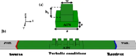
Figure 1(a) shows a schematic design of a phononic structure unit cell that contains a micro-strip deposited on a piezoelectric membrane. The geometrical design parameters are defined as follows: a is the lattice constant, e is the thickness of the AlN membrane, and (h1, w) are respectively the (height, width) of AlN.
Fig. 1 (a) Schematic representation of the unit cell. (b) Schematic setting used
for the computation of the transmission through a phononic crystal containing five unit cells.
The numerical results including dispersion and transmission curves are calculated by the finite element method (FEM) using Comsol Multiphysics software. For the dispersion curves, the Bloch periodic boundary conditions were applied to the unit cell shown in Fig. 1(a). The dispersion curves will be presented in terms of the reduced frequency (f.a) versus the Bloch wave-vector inside the first Brillouin zone along X direction (Fig. 2(a)), where f and a represent the frequency and lattice constant respectively. For the transmission spectra, a finite system along the x direction containing five unit cells and infinite along the y-direction is considered (Fig. 1(b)). Perfectly Matched Layers (PMLs), which can absorb waves and avoid reflection, are applied on each side of the structure along the finite-length direction. The incident wave is a S0 Lamb wave of the plate launched by applying a prescribed harmonic acceleration ax in the (y,z) plane at the left side of the crystal and
propagating along the x axis. The transmitted acceleration value is detected and recorded in the far field on the right side of the crystal. The transmission coefficient is normalized to the acceleration field propagating in the homogeneous plate.
We first calculate the band structure of a phononic crystal composed of AlN membrane and only micro-strips. Figure 2(a) shows the calculated band structure along the X direction. The geometrical parameters are chosen in order to obtain wide band-gaps (i.e., e/a = 0.22, h1/a = 0.32, w/a = 0.68) and to be compatible with standard micromachining process for operation frequency in the GHz range. Figure 2(b) shows the corresponding normalized transmission spectrum along the X direction.
Fig. 2 (a) Band structure of a phononic crystal composed of corrugated AlN
membrane. (b) Transmission spectrum for the S0 mode through a phononic
crystal containing five unit cells.
Figure 2(a) shows two band gaps: an upper band-gap (the widest) located in the frequency range 3500 m/s < f a < 5100 m/s where the dispersion curves fold back at the limit of the Brillouin zone (Bragg condition). The lower band-gap appears in the frequency range 1500 m/s < f a < 2300 m/s (Fig. 2(a)). The opening of this gap results from the crossing of two Lamb mode dispersion curves, namely the first crossing between A0 and S0 modes. As indicated in Fig. 2(b) strong dips are observed in the transmission spectrum and correspond very well to the stop band frequencies shown in Fig. 2(a).
We propose now to use the property cited above for the design of a new kind of resonator cavity structure. The cavity design is shown in Fig. 3(a). The super cell is composed of a periodic structure that contains one line of AlN micro-strip with a disc shape layer surrounded from each side by two lines of AlN micro-strip without disc. In this section, we will keep fixed the membrane and AlN micro-strip thicknesses (e/a = 0.22, h1/a =
2 0.32 and width w/a = 0.68) and we will add a periodic disc cap layer made of gold on the top of the central micro-strip. The cap layer is characterized by its height h2 = 0.07a and radius r1
=
0.16a. Our goal consists in considering the effect of a thin layer presenting a strong contrast in elastic and density properties on the evolution of band-diagrams and transmission spectra.Fig. 3 (a) Schematic representation of a supercell. (b) Schematic setting used
for the computation of the transmission through a phononic crystal containing five unit cells.
Figure 4(a) shows the band structure of the phononic crystal computed using the super-cell model. First, we can notice that the two band-gaps observed for the case h2 = 0 (Fig. 2(a)) still exist with approximately the same width. Secondly, Fig. 4(a) shows the existence of some nearly flat branches (labeled 1, 2 and 3) inside the upper band gap. The mode labeled 1 corresponds to the bending mode as shown by the total displacement field distribution (Fig. 4(c)). The behavior of the displacement field distribution for the modes labeled 2 and 3 is similar to the whispering gallery modes (WGMs) with quadrupolar shape (Fig. 4(c)). Figure 4(a) clearly shows that the three modes are mainly confined in the disc shaped layer enabling the possibility to engineer the properties of these kind of modes by tuning the geometrical parameters of the latter including thickness, radius, and shape. Fig. 4(b) shows the transmission coefficient as a function of the reduced frequency for a phononic crystal strip composed of five unit cells (Fig. 3(b)). This figure clearly shows two transmission dips in the frequency domains [1560-2200 m/s], and [3500-5120 m/s] which are consistent with the band-gaps calculated from the band structure (Fig. 4(a)). We can also notice the existence of two peaks located at 3418 m/s and 4391 m/s respectively. The frequencies of these peaks are in accordance with the flat modes labeled 1, 2 in Fig. 4(b). However, due to its symmetry, the flat mode labeled 3 vibrating along the [110] direction (Fig. 4(c)) does not present any coupling with the S0 mode launched in the x direction, which explains its absence in the transmission spectrum (Fig. 4(b)).
Fig. 4 (a) Band structure of a phononic crystal constituted of a periodic
repetition of a super cell (b) Transmission spectrum for the S0 mode through
a phononic crystal containing five unit cells. (c)Total displacement field distribution for flat modes labeled 1, 2 and 3 in (a).
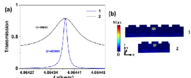
Also, we studied the quality factor of the mode labeled 2, in the cavity design, as a function of the phononic crystal size. The size is defined as the number of disc-free lines surrounding the central micro-strip with Au disc shaped layer. As we know, the actual Q factor is based on several energy loss mechanisms, such as thermo-elastic damping, surface loss, and anchor loss. In this study, we consider only the Q factor related to mechanical energy leakage (support loss) from the disc resonator to the supporting structure that serves for us as a reference for the design of the confined radial contour modes. The Q factor is calculated using the ratio between the central frequency and the full width at half maximum of the transmission peaks. Figure 5 shows the results for one and two micro-strips surrounding the cavity layer. First, we can notice that as the number of phononic crystal layers increases, the location of the resonant frequency peak remains unchanged. Secondly, we can notice that the quality factor drastically increases by increasing the phononic crystal size
giving rise to an efficient acoustic isolation as it is described in the displacement field displayed in Fig. 5(b). In comparison to previous cavity designs reported in the literature and using similar calculation method [5, 14, 16], the proposed structure enables to achieve the much higher Q factor with minimal phononic crystal size.
Fig. 5 (a) Evolution of the quality factor as a function of the size of the
structure (b) Total displacement field distribution for the flat modes labeled 2 at point in Fig4(a).
Conclusion: We have proposed an alternative and useful platform to
obtain highly confined disc shape radial contour modes, characterized by their high Q factor and surface mode nature. The structure is composed of a corrugated piezoelectric membrane and disc shape thin films deposited on the micro-strip surface. This work can be useful for designing advanced electroacoustic waves devices exhibiting performances that may surpass their conventional micro/nano electromechanical systems for sensing applications.
Acknowledgments: We acknowledge support from the French "Agence
Nationale de la Recherche" through the project grant N ° ANR-12-BS09-0015-01.
References
1. P. Deymier, Acoustic Metamaterials and Phononic Crystals (Springer, Berlin) (2013).
2. A.M. Kosevich, JETP Lett. 74, 559 (2001).
3. T.-T. Wu, L.-C. Wu, Z.-G. Huang, J. Appl. Phys. 97, 094916 (2005). 4. S. Mohammadi, A. A. Eftekhar, W. D. Hunt, and A. Adibi, Appl. Phys. Lett. 94, 051906 (2009).
5. D. Goettler, M. Su, Z. Leseman, Y. Soliman, R. Olsson, and I. El-Kady, J. Appl. Phys. 108, 084505 (2010).
6. S. Mohammadi, A. Adibi, J. Microelectromech. Syst. 21, 379 (2012). 7. S. Villa, R. Toress, R. Lucklum, Electronics Letters, Vol. 51, 545, (2015).
8. R. Pourabolghasem, A. Khelif, A. Eftekhar, S. Mohammadi, and A. Adibi, Electronics Letters, Vol. 48, 1147, (2012).
9. Y. Achaoui, A. Khelif, S. Benchabane, L. Robert, V. Laude, Phys. Rev. B. 83, 104201 (2011).
10. S.Yankin, A.Talbi, Y.Du, J.C.Gerbedoen, V.Preobrazhensky, P. Pernod, O.Bou Matar, J. Appl. Phys. 115, 244508 (2014).
11. R. Pourabolghasem, S. Mohammadi, A. Eftekhar, A. Khelif, A. Adibi, Appl. Phys. Lett. 105, 231908 (2014).
12. S. Hemon, A. Akjouj, A. Soltani, Y. Pennec, Y. El Hassouani, A. Talbi, V. Mortet and B. Djafari-Rouhani, Appl. Phys. Lett. 104, 063101 (2014).
13. J. Ma, Z. Hou, M.B. Assouar, J. Appl. Phys. 115, 093508 (2014). 14. P. Jiang, X. Wang, T. Chen, and J. Zhu, J. Appl. Phys. 117, 154301 (2015).
15. C.-Y. Sun, J.-C. Hsu, and T.-T. Wu, Appl. Phys. Lett. 97, 031902 (2010).
16. Y. Jin, N. Fernez, Y. Pennec, B. Bonello, R. P. Moiseyenko, S. Hemon, Y. Pan, B. Djafari-Rouhani, Phys. Rev. B. 93, 054109 (2016). 17. A. Talbi, A. Soltani, V. Mortet, J.-C. Gerbedoen, J.C. De jaeger, P. Pernod, Diam. Relat. Mater. 22, 66 (2012).
18. A. Soltani, A. Talbi, J.-C. Gerbedoen, J.C. De jaeger, P. Pernod, V. Mortet, A. Bassam, 2014 IEEE International Ultrasonics Symposium, Chicago, IL, pp. 2047-2050 (2014).