HAL Id: hal-01151014
https://hal.archives-ouvertes.fr/hal-01151014
Submitted on 12 May 2015
HAL is a multi-disciplinary open access
archive for the deposit and dissemination of
sci-entific research documents, whether they are
pub-lished or not. The documents may come from
teaching and research institutions in France or
abroad, or from public or private research centers.
L’archive ouverte pluridisciplinaire HAL, est
destinée au dépôt et à la diffusion de documents
scientifiques de niveau recherche, publiés ou non,
émanant des établissements d’enseignement et de
recherche français ou étrangers, des laboratoires
publics ou privés.
Preserving the Global Consistency of Dynamic
Reconfiguration
Mohammad Charaf Eddin, Zoubir Mammeri
To cite this version:
Mohammad Charaf Eddin, Zoubir Mammeri. Preserving the Global Consistency of Dynamic
Re-configuration. IEEE/ACIS International Conference on Software Engineering, Artificial Intelligence,
Networking and Parallel/Distributed Computing - SNPD 2013, Jul 2013, Honolulu, United States.
pp. 71-76. �hal-01151014�
O
pen
A
rchive
T
OULOUSE
A
rchive
O
uverte (
OATAO
)
OATAO is an open access repository that collects the work of Toulouse researchers and
makes it freely available over the web where possible.
This is an author-deposited version published in :
http://oatao.univ-toulouse.fr/
Eprints ID : 12442
To link to this article : DOI :10.1109/SNPD.2013.82
URL :
http://dx.doi.org/10.1109/SNPD.2013.82
To cite this version : Charaf Eddin, Mohammad and Mammeri, Zoubir
Preserving the Global Consistency of Dynamic Reconfiguration
.
(2013) In: IEEE/ACIS International Conference on Software
Engineering, Artificial Intelligence, Networking and
Parallel/Distributed Computing - SNPD 2013, 1 July 2013 - 3 July
2013 (Honolulu, United States).
Any correspondance concerning this service should be sent to the repository
administrator:
[email protected]
Preserving The Global Consistency of Dynamic
Reconfiguration
Mohammad Charaf Eddin IRIT – Paul Sabatier University
Toulouse, France [email protected]
Zoubir Mammeri IRIT – Paul Sabatier University
Toulouse, France [email protected]
Abstract—Many component-based systems need to modify their behavior or structure at run time in order to adapt the continuous change of user requirements or working environ-ments. Change management is an essential part of reconfigurable systems. Dynamic reconfiguration helps these systems to evolve incrementally for one configuration to another at execution time. Many approaches have been proposed to support dynamic reconfiguration in various kinds of systems.
This paper introduces a new approach for preserving the global consistency of dynamic reconfiguration using Alloy spec-ification language. Alloy is a powerful language for modeling and describing the structure and the behavior of a system by expressing its constraints. The approach starts by modeling the structure of a reconfigurable system, and then a set of predicates are proposed to describe the dynamic behavior of a reconfigurable system. Finally, an analysis is done to analyze the previous specifications using Alloy Analyzer.
Keywords—component-based systems, dynamic reconfiguration, software evolution.
I. INTRODUCTION
Many contemporary systems aim to change their con-figuration at execution time without stopping or restarting them. Dynamic reconfiguration[7], [1], [2] is a mechanism that allows a system to evolve incrementally from one configuration to another at execution time. Dynamic reconfiguration can help the system to improve the adaptability, the availability, maintainability, and the performance.
Usually, dynamic reconfiguration changes the system at runtime by performing structural modifications like adding new components to the system, removing old components, binding or unbinding the components. The reconfiguration primitives should be done in safe way which ensures the correctness, integrity and the consistency of the new modified system. Many operating systems and middlewares provide some facilities for loading and unloading the components (e.g., dynamic link libraries in UNIX) at run time without taking into consideration the consistency preservation problem. Therefore, preserving the consistency is the most important axis, which distinguishes the dynamic reconfiguration from these runtime facilities.
The consistency can be divided into two categories: The global consistency and the local consistency. Global consis-tency means to satisfy the system invariants. This is done by preventing the reconfiguration operations from violating the system invariants. Local consistency means to prevent the
information loss. Preserving the consistency in reconfigurable systems, during and after the reconfiguration process, is a tedious task[7], [2]. Several works have been done in the litera-ture to preserve the local consistency. One of the most popular works is done by Kramer and Magee[7]. They proved that the quiescence criterion or the safe state criterion was sufficient to ensure the local consistency during the reconfiguration of a distributed system.
Different approaches[13], [6] have been proposed to pre-serve the global consistency. The common thing between these approaches is to model, specify, and constrain the dynami-cally reconfigurable systems. In this paper, our approach for preserving the global consistency has three steps: Firstly, we propose a general model to specify the system structure using a formal specification language and then proposing a set of constraints to represent the system invariants. Respecting the satisfaction of the set of constraints is very important to ensure the consistency during and after the reconfiguration process. Finally, we use an analyzer in order to analyze the proposed model.
Reconfigurable systems should be modular. Usually, A portion of the modular system is suspended during the re-configuration operation while the rest parts are still active. Therefore, in this paper we focus on the big picture by looking at the system as a set of components rather than diving to the statements and variables depths. Component-Based Software Engineering (CBSE)[11], [4] is a powerful technology to create complex systems because it provides strong features like assembling the building blocks (components) to build complex modular system, software reuse, and complex management. Therefore, we will investigate the consistency preservation problem in the component based systems domain.
Our approach of specifying the reconfigurable component-based systems starts by showing how to specify the structure of the configuration of a system. Then we show how to model the dynamic reconfiguration operations with the constraints, how to preserve the global consistency, and how to check whether a reconfiguration change is consistent or not.
The rest of this paper is structured as follows. First, section 2 proposes a structural model of reconfigurable component-based systems. Section 3 presents the global consistency and shows how to preserve it. Section 4 shows how to reconfigure a running system and how to analyze the proposed model using Alloy analyzer. Finally, we discuss the related work in section 5, and section 6 is the concluding section that summarizes the
paper and presents the future work.
II. A STRUCTURALMODEL FORRECONFIGURABLE
SYSTEMS
A component based system can be described as a set of components connected to each other using interfaces. Each component has a set of provided interfaces, and a set of required interfaces. For example, a component C has a set of provided interfaces we denoted by provide(C) and a set of required interfaces required(C).
A reconfigurable component based system (RS) has the ability to change its structure and behavior during the execu-tion time. Usually, the change is done by making structural modifications. After the reconfiguration operations (Ropt) are completed a new conf iguration of the system is born. There-fore, reconfigurable system model should support the dynamic aspects of such systems. We can describe the dynamicity of a system as a transition from one configuration to another. So, the reconfiguration operations like add, remove, replace etc. can be seen as transition operations which move the system from configuration to another . For example, figure 1 shows a simple component based system which evolves during the execution time from the old configuration (a) to new the configuration (b). we can notice that many structural modi-fications have been made during the reconfiguration process. For instance, the component C5 was added and linked to C2 while the binding between C3 and C2 was removed.
Fig. 1. Evolution of a system at runtime
To this end, we can look at a dynamically reconfigurable system during its life as a sequence of configurations. Each configuration is defined by a set of connected components. Each component provides a set of interfaces and requires a set of interfaces. The transition from one configuration to another configuration is normally can be done by the reconfiguration operations (Ropt). Therefore a system evolution is the process of transition from an old configuration to a new one. The following equation shows multiple configurations of a recon-figurable system RS during its life.
RS = Conf0 −−−→Ropt Conf1 −−−→Ropt ... (1)
A. Modeling The Structure of a Configuration
A configuration is defined as a set of components which are connected to each other by interfaces. To specify our model by a formal modeling language we use Alloy[5] specification language. There are many motivations behind choosing Alloy language. Alloy is a lightweight, scalable, high performance language. Alloy also is based on formal specification and is amenable to a fully automated analysis.
In Alloy, the structures are modeled using atoms and relations. Atoms are the primitive entities which have the following properties: indivisible, uninterpreted and immutable. A relation is a set of tuples that relates the atoms. For example, configurations, components and interfaces are atoms. To say that configurations can contain components and components can contain interfaces. We can define a set of relations that associates configurations, components and interfaces.
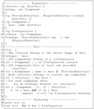
1−−−−−−−−−−−−−−− S i g n a t u r e s −−−−−−−−−−−−−−−− 2 a b s t r a c t s i g I n t e r f a c e { 3 b e l o n g : one Component 4 } 5 s i g P r o v i d e d I n t e r f a c e , R e q u i r e d I n t e r f a c e e x t e n d s I n t e r f a c e {} 6 s i g Component { 7 h a v e : some I n t e r f a c e 8 } 9 s i g C o n f i g u r a t i o n { 10 c o n t a i n : s e t Component , 11 b i n d i n g s : P r o v i d e d I n t e r f a c e one −> one R e q u i r e d I n t e r f a c e 12 } 13−−−−−−−−−−−−−−−− F a c t −−−−−−−−−−−−−−−−−−− 14 f a c t { 15−−The r e l a t i o n b e l o n g i s t h e m i r r o r image o f h a v e 16 b e l o n g = ˜ h a v e 17−−A l l c o m p o n e n t s b e l o n g t o a c o n f i g u r a t i o n 18 a l l c : Component | c i n C o n f i g u r a t i o n . c o n t a i n 19−−A l l c o m p o n e n t s h a v e a t l e a s t one p r o v i d e d i n t e r f a c e
20 a l l c : Component | some ( c . h a v e & P r o v i d e d I n t e r f a c e ) 21−−Each i n t e r f a c e b e l o n g s t o e x a c t l y one component 22 a l l i : I n t e r f a c e | one h a v e . i 23−−F o r e a c h component t h e r e 24−− a r e no b i n d i n g s b e t w e e n i t s i n t e r f a c e s 25 a l l c : Component , i 1 , i 2 : I n t e r f a c e | 26 i 1 i n c . h a v e and i 2 i n c . h a v e 27 i m p l i e s i 1−>i 2 ! i n C o n f i g u r a t i o n . b i n d i n g s 28 } 29−−−−−−−−−−−−−−−− A n a l y z i n g −−−−−−−−−−−−−−−− 30 p r e d t e s t {} 31 r u n t e s t f o r 4 b u t 1 C o n f i g u r a t i o n
Fig. 2. A structural model for a configuration
Figure 2 proposes a structural model of a reconfigurable component based system. The model introduces three sig-natures: Interface, Component, Configuration. Each of them represents a set of objects.The Interf ace signa-ture represents a set of interfaces. The keyword abstract in the declaration means that this signature has no elements except those belonging to its extensions. The Interf ace defines the binary relation belong which relates each interface with its components. P rovidedInterf ace and RequiredInterf ace are disjoint extensions of Interf ace. So, each interface should be either a provided interface or a required one. The signature Component represents a set of components and defines the binary relation have which relates each component with its interfaces. At line 16, we have added a fact which states that the relation belong is the transpose of the relation have. The keyword some indicates the multiplicity and says that each component has at least one interface. The final signature is Conf iguration. It represents a set of interconnected compo-nents. The relation contain relates each configuration with a set of components. The ternary relation bindings contains the existing connections in the configuration.
Declaring a model without constraining it may produce some anomalies or unwanted cases. For example, we may have an independent component which does not belong to any configuration. To prevent such anomalies we add a set of facts in order to constrain the model. The first fact, at line 18 in figure 2, states that there is no independent components i.e. each component belongs to a configuration. The second fact says that each component should have at least one provided interface. The third fact says that each interface belong to one component i.e. there isn’t any component shares the same interface with another component. Finally, the fourth fact at line 25 prevents the bindings between the interfaces that belong to the same component.
To analyze the previous model by using Alloy analyzer, we add an empty predicate test and then we run it. The command run specifies a scope for each signature. Usually, scopes are used only for analysis purposes and limiting them does not mean to limit the whole model. In our example we limit the scope to at most four objects in each signature, except for the configuration signature which is limited to one configuration because we don’t yet add the dynamic reconfiguration operations to the model. Executing the run commands produce a set of instances of this model.
B. Modeling Dynamic Reconfiguration Operations
Dynamic reconfiguration modifies the component based system at runtime by making structural modifications. In this paper, we will take into consideration five kinds of dynamic reconfiguration primitives. the following list shows the five operations:
- Add aims to add a new component C to the current reconfiguration Conf . So the new configuration state will be Conf′.contain= Conf.contain + C
- Remove aims to remove an old component C to the current reconfiguration Conf . So the new configuration state will be Conf′.contain= Conf.contain − C
- Replace aims to replace an old component C by a new component C′. So the new configuration state will be
Conf′.contain= Conf.contain − C + C′
- Link aims to create a new link between a provided interface and a required interface in the current con-figuration. The state of the new configuration will be Conf′.bindings = Conf.bindings + proInter− >
reqInter
- Unlink aims to remove an existing link between a pro-vided interface and a required interface in the current configuration. The state of the new configuration will be Conf′.bindings= Conf.bindings − proInter− >
reqInter
As we notice, in modeling we focus on the state of the system before and after dynamic reconfiguration modification. we don’t search how to do the modifications like imperative pro-gramming. By comparing the prestate and the poststate of the system we can determine whether a dynamic reconfiguration operation is valid or not.
To represent the dynamic reconfiguration operations in Alloy, we can add a set of predicates in order to describe the dynamic behavior of a system. The predicate in Alloy
defines a reusable constrain. The general form of a dynamic reconfiguration operation will be as the following:
1 p r e d r e c o n f i g u r a t i o n O p e r a t i o n ( c o n f , c o n f ’ : C o n f i g u r a t i o n , . . . ) 2 { 3−−P r e c o n d i t i o n s 4−−Dynamic r e c o n f i g u r a t i o n o p e r a t i o n 5−−P o s t c o n d i t i o n s 6 }
The reconf igurationOperation predicate has a list of argu-ments. The arguments always contain the state of the config-uration before and after the reconfigconfig-uration operation conf , conf′. The other arguments can vary according to the kind of
the the reconfiguration operation.
The goal of preconditions and postconditions is to ensure that the global consistency of the system is always preserved. This is done by checking whether a reconfiguration change is valid or not. A valid reconfiguration change should not violate the system invariants. For example, suppose that our system has a binary tree structure. We want to add a new child C′ to
a specific node N . The preconditions should assert that N has at most one child. The postconditions should assert that the whole structure of the system remains a binary tree structure after the addition operation.
The preconditions and the postconditions usually take the form of assertions. These assertions are used to ensure whether a reconfiguration change satisfies the system invariants or not. The invariants are almost related to the structure of the component-based system. Each structure has a specific set of invariants. For example, the set of invariants for a file system are different from those used in a secure email system.
Nevertheless, we can find some common invariants for all kinds of component-based systems. For example, each required interface in the new configuration should be connected to a provided interface after the termination of the reconfiguration. So, we can add a postcondition to the model to assert whether all required interfaces are connected or not.
1 p r e d l i n k ( c o n f , c o n f ’ : C o n f i g u r a t i o n , i 1 : P r o v i d e d I n t e r f a c e , i 2 : R e q u i r e d I n t e r f a c e ) 2 { 3−−some p r e c o n d i t i o n s 4 i 1 . b e l o n g ! = i 2 . b e l o n g 5 i 1−>i 2 n o t i n c o n f . b i n d i n g s 6−−o p e r a t i o n 7 c o n f ’ . b i n d i n g s = c o n f . b i n d i n g s + i 1−>i 2 8−−some P o s t c o n d i t i o n s 9 one c o n f ’ . b i n d i n g s . i 2 10 }
Fig. 3. The predicate of the link primitive
In figure 3 we give an example to show how we can specify a dynamic operation like link using the Alloy predicates. The link predicate has four arguments. The prestate and the post-state of the configuration, a provided interface and a required interface. Some preconditions are checked before changing the state of the conf iguration. The first precondition is to ensure that the two interfaces do not belong to the same component. This precondition aims to check the satisfaction of the fourth invariant in figure 2 at line 25. The second precondition ensures
that there is no link between the two interfaces. Then at line 6, the state of the conf iguration is changed by adding new binding to the set of bindings which contains all the existing links. Finally, a postcondition is used ensure that there is only one link between the target interfaces.
III. PRESERVING THEGLOBALCONSISTENCY OF
RECONFIGURABLESYSTEMS
A reconfigurable system has global consistency if and only if its invariants are always preserved during the running time. Reconfiguration operations should not violate the system in-variants. Therefore, in order to maintain the global consistency for a system, any reconfiguration operation violates the system invariants will be rejected.
The structure of a reconfigurable system can be modeled in Alloy by using the signatures. Each signature has a set of objects. Alloy relations specify the way of interaction between these objects. For each signature, We can distinguish between three categories of invariants.The following list shows these categories:
- Universal invariants All objects belong to the signature should preserve their universal set of invariants. For instance, let us consider the Component signature from our model. A universal invariant related to this signature is: Each component in the Component signature should has at least one provided interface.
- Group invariants This set of invariants are concerned with a subset of the signature objects. In Alloy, we can declare a subset using the keyword in. For example, we can declare a subset which represent the file system com-ponents as the following:sig FileSystem in Component. The F ilesystem subset will have additional group of invariants which should specify the prohibited behaviors for this subset.
- Local invariants This set of constrains should be pre-served only by a specific object from the signature. For example, each file system has a specific object which is the root directory. A typical constrain which is related only to this object is: The root has no parent. As a result, the root object should satisfy the universal invariants, the group invariants and its local invariants.
Usually, The system invariants are related to its structure and its behavior. Each system has its own set of invariants. Invariants preserve the system consistency by constraining the system and by preventing the unwanted behaviors. In Alloy, we use the facts to declare the system invariants. The facts may be universal which should be true for all objects in the signature. In figure 2, we have declare four universal facts which use the universal quantifier all. Some facts may be partial which should be true for all objects in a specific group or for one specific object.
Typically, Alloy facts are used to express the invariants and to force them to be true in the model. Alloy always remove any solution which violate any fact in the model. But, we still need a mechanism to check whether some claims conform our model or not. In Alloy, we can express these claims by using assertions and then we can ask the analyzer to check whether the assertion follows from the facts or not. Checking invalid assertion will produce a counterexample. For example, in
our model of a reconfigurable component-base systems if the analyzer generates counter examples. This means that either there are some flaws in the model design or the provided reconfiguration commands are invalid.
Assertions can express the different properties of the re-configurable system. They can help to detect the unseen flaws in the model or in the reconfiguration commands. Therefore, Alloy assertions can be used to check whether a reconfigu-ration change (commands) can produce a valid configureconfigu-ration or not. That’s to say, Alloy analyzer will check if the new configuration conf′ conforms the system model invariants
or not. For example, In our reconfigurable component-based model. In order to produce a new consistent configuration, it is very important to ensure that all required interfaces in the configuration are connected. That’s to say, after the reconfiguration is done there is no component still need some services to work. 1 2 a s s e r t N o F r e e R e q I n t{ 3 a l l i : R e q u i r e d I n t e r f a c e , c o n f : C o n f i g u r a t i o n | some c o n f . b i n d i n g s . i 4 } 5 6 c h e c k N o F r e e R e q I n t
Fig. 4. An assertion to check whether all required interfaces are connected or not
Figure 4 shows an Alloy assertion N oF reeReqInt. The goal of this assertion is to verify that there is no unconnected required interface in the current configuration. This assertion can be used after the reconfiguration predicates to test the satisfactions of all required interfaces. If there are at least one free required interfaces then the reconfiguration commands are invalid and they will an inconsistent system. Therefore, invalid reconfiguration commands will be rejected.
In Alloy, we declare an assertion by using the keyword assert. Then we can check the assertion by using the com-mand check. The check comcom-mand instructs the Alloy analyzer to search for a counter example of an assertion. Alloy permits us to specify the scope in the check command. The analyzer will use the scope to determine the size of objects (instances) of each top-level signature. In figure 4 at line 6 we do not specify the scope, so the default scope will be 3 for top-level signature.
By running the command check in figure 4, if the analyzer tell us that there are no counter examples then the assertion is valid in the proposed scope. we can extend the scope more to increase the research field and to see the new feedback. The analyzer may produce some counter examples. Counter examples has two indications. First, they show that the reconfiguration commands are not valid and may generate inconsistent system. Therefore, the reconfiguration commands should be rejected. Second, They show that there are some hidden flaws in the model design. So, the model need some more modifications.
To this end, we have used Alloy signatures and relations to model a component-based reconfigurable system. Alloy pred-icates have been used to specify the dynamic reconfiguration primitives. Then, The Alloy facts have been used to represent
the system invariants. Alloy assertions have been used to verify if the reconfiguration commands are valid or not.
IV. RECONFIGURING ANDANALYZING ARUNNING
SYSTEM
In previous sections, we have been proposed a general dynamic model for reconfigurable component-based systems. In this section firstly, we explain how to reconfigure a system at runtime. Then, we focus on showing how Alloy analyzer can test whether the new configuration is compliant with the proposed model or not.
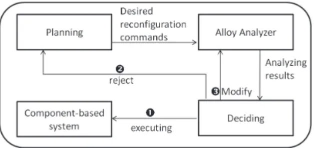
Fig. 5. shows the different stages of reconfiguring a running system
From our perspective, the standard approach for modifying a running system has four stages. The first stage is planning, planning focus on searching for the new structural modifica-tions in order to satisfy user requirements and to adapt the working environment. Planning stage specify what are the desired reconfiguration commands as we see in figure 5. The second stage is analyzing, in this stage Alloy analyzer is used to check whether the reconfiguration commands can produce a new consistent configuration or not. A consistent configuration is compliant with the system model. Depending on the results of analyzing, the deciding stage makes the suitable decision. The deciding stage has tree kinds of decisions. The first decision is to accept to execute the desired reconfigurations on the concrete system if the desired reconfigurations are valid and they can produce a consistent configuration of the system. The second decision is to refuse the suggested reconfiguration because they violate the system consistency. We go back to the planning stage if the desired reconfigurations are rejected. The final decision of the deciding stage is to modify the model itself. In some cases we can discover that there is a need to modify the model design or the system invariants in order to accommodate the new requirements or to repair the hidden flaws. For example, suppose that there is an invariant says that ”the total number of components should not exceed ten components”. Then, any reconfiguration commands to add more than ten components will be rejected. So, a decision may be taken to modify the system model.
Now, let us focus on the analyzing stage by showing how can the Alloy Analyzer check the consistency of a reconfiguration change. Suppose that we want to reconfigure the system shown in figure 1 at running time. let us suppose that the current configuration of the system is(a). In order to satisfy the new requirements of the users or the working envi-ronment, some structural modifications have been proposed. These modifications will change the system state and will generate the new configuration (b). Now let us analyze these
changes to know whether the reconfiguration preserves the global consistency or not. According to the proposed model in figure 2, there are five signatures. Each signature in the prestate(a) contains a set of objects as following:
Interf ace= {i1, i2, i3, i4, i6, i5, i7, i8} P rovidedInterf ace= {i2, i3, i7, i8} RequiredInterf ace= {i1, i4, i5, i6} Component= {c1, c2, c3, c4} Conf iguration= {a}
In the prestate a the model relations contain the following tuples:
belong= {(i1, c1), (i2, c1), (i3, c2), (i4, c2), (i5, c2), (i6, c3) ,(i7, c3), (i8, c4)}
have= {(c1, i1), (c1, i2), (c2, i3), (c2, i4), (c2, i5), (c3, i6) ,(c3, i7), (c4, i8)}
contain= {(a, c1), (a, c2), (a, c3), (a, c4)}
bindings= {(a, i2, i6), (a, i3, i1), (a, i7, i4), (a, i8, i5)} To make the desired structural modifications in order to gener-ate the new configuration(b), we need to add the component c5 which has the provided interface i9. Therefore, the set of reconfiguration commands are:
add c5, unlink (i7, i4), link (i9, i4).
The previous reconfiguration commands will generate a new configuration(b). by modifying the system signatures and relations. The model signatures and relations in the new state b will be modified as the following:
Interf ace′= Interf ace + i9
P rovidedInterf ace′= P rovidedInterf ace + i9
RequiredInterf ace′= RequiredInterf ace
Component′= Component + c5
Conf iguration′= Conf iguration + b
Interf ace′.belong= Interf ace.belong + (i9, c5)
Component′.have= Component.have + (c5, i9)
b.contain= a.contain + c5
b.bindings= a.bindings − (i7, i4) + (i9, i4)
In order to check the conformance of the new configuration (b) with the proposed model. Then, we should feed the Alloy analyzer with the old configuration(a) and the reconfiguration commands. There are various ways to feed them. The way that we have chosen is defining a singleton signatures which represent all the existing objects of the configuration (a). Then we have defined a predicate which contains all the reconfiguration commands predicates. Then we have used the run to check whether the configuration(b) is compliant with the model or not.
After the run command has been executed. Alloy analyzer showed that the configuration b is consistent and there is no violation reported. All the model facts (invariants) were satisfied. After that we have run the assertion N oF reeReqInt shown in figure 4 to check whether all required interfaces are linked. The tool has showed that there is no free required interface. These analyses indicate that the transition from the configuration a to the configuration b is safe and the global consistency is preserved.
After we have verified that the reconfiguration commands are safe and they can produce a consistent configuration. The suitable decision of the deciding stage (cf. figure 5) is the first one. The first decision says that the reconfiguration commands are safe and they can be executed on the concrete component-based system.
V. RELATEDWORK
Several work have been carried out in order to specify and to preserve the global consistency of the reconfigurable systems using different approaches.
The authors of [13] proposed two methods to preserve the global consistency of reconfigurable systems. The first one is for specifying the programmed change where the changes are identified and declared at the design time. The second one is for constraining the unpredictable change where changes are specified at the running time. In order to preserve the global consistency, the system has a set of invariants and the reconfiguration operations must not violates these invariants.
The authors of [9] proposed a transactional approach to ensure the preservation of the system consistency. They have provided a model of configurations and reconfiguration. In order to maintaun the consistency, they have used the invariants and the pre/post conditions. Alloy language have been used in order to specify the system invariants and conditions. They also used Alloy to check consistency. However, Their work focused only on modeling and specifying Fractal[3] component model. While, the approach that we have proposed in this paper is general and not related to a specific component model.
Some approaches have been used the UML modeling language. UML is the de facto standard for software modeling, from both the industrial and academic perspective. However, UML is poor in specifying the reconfigurable systems. There-fore, many profiles have been proposed to bridge this gap by extending UML language. For example, The authors of [6] Pro-posed an approach to specify the static and the dynamic aspect of software architecture by using graph rewriting rules. The approach also integrates the UML2.0[10] and the OCL[12], [8] languages in order to describe the behavior and the relations between the configuration actions.
VI. CONCLUSION
In this paper, we propose an approach to preserve the global consistency of a reconfigurable component-based sys-tem. The approach starts by specifying a general model using a declarative formal language (Alloy). We have shown that the system structure can be modeled by using Alloy signatures and relations. Additional relations and facts can be added to this model to represent any structure. To model the reconfigurabil-ity, we have used Alloy predicates. Each predicate represents a reconfiguration operation. Multiple predicates can be gathered in another predicate to represent the desired reconfiguration commands. Preserving the global consistency means to respect the system invariants. In Alloy, system invariants can be modeled by using facts. Finally, we have showed the benefit of using automated formal language by running many tests to check the safety of the reconfiguration commands. We can decide by using Alloy analyzer whether the reconfiguration operations preserve the global consistency or not.
REFERENCES
[1] Thais Batista, Ackbar Joolia, and Geoff Coulson. Managing dynamic reconfiguration in component-based systems. In EWSA 2005 2 nd
European Workshop on Software Architectures, pages 1–17. Springer, 2005.
[2] Christophe Bidan, Val´erie Issarny, Titos Saridakis, and Apostolos Zarras. A dynamic reconfiguration service for corba. In In 4th Intl.
Conf. on Configurable Dist. Systems, pages 35–42. IEEE Computer Society Press, 1998.
[3] Eric Bruneton, Thierry Coupaye, Matthieu Leclercq, Vivien Qu´ema, and Jean-Bernard Stefani. The fractal component model and its support in java. Software: Practice and Experience, 36(11-12):1257–1284, 2006. [4] G.T. Heineman and W.T. Councill. Component-based software
engi-neering: putting the pieces together, volume 17. Addison-Wesley USA, 2001.
[5] D. Jackson. Software Abstractions: logic, language, and analysis. MIT press, 2006.
[6] M.H. Kacem, M.N. Miladi, M. Jmaiel, A.H. Kacem, and K. Drira. Towards a uml profile for the description of dynamic software archi-tectures. COEA 2005, pages 25–39, 2005.
[7] Jeff Kramer and Jeff Magee. The evolving philosophers problem: Dynamic change management. IEEE Transactions on software
engi-neering, 16:1293–1306, 1990.
[8] Object Constraint Language. Version 2.3.1 document
formal/2012-01-01, 2.3.1 edition, 2012.
[9] Marc L´eger, Thomas Ledoux, and Thierry Coupaye. Reliable dynamic reconfigurations in a reflective component model. Component-Based
Software Engineering, pages 74–92, 2010.
[10] U.M.L.S. Specification. v2. 0 document 05-07-04. Object Management
Group, pages 20–04, 2004.
[11] C. Szyperski, D. Gruntz, and S. Murer. Component software: beyond
object-oriented programming. Addison-Wesley, 2002.
[12] J.B. Warmer and A.G. Kleppe. The object constraint language: getting
your models ready for MDA. Addison-Wesley Professional, 2003. [13] A.J. Young and JN Magee. A flexible approach to evolution of
reconfigurable systems. In Configurable Distributed Systems, 1992.,