HAL Id: hal-02749411
https://hal-enac.archives-ouvertes.fr/hal-02749411
Submitted on 9 Dec 2020
HAL is a multi-disciplinary open access
archive for the deposit and dissemination of sci-entific research documents, whether they are pub-lished or not. The documents may come from teaching and research institutions in France or abroad, or from public or private research centers.
L’archive ouverte pluridisciplinaire HAL, est destinée au dépôt et à la diffusion de documents scientifiques de niveau recherche, publiés ou non, émanant des établissements d’enseignement et de recherche français ou étrangers, des laboratoires publics ou privés.
Lucille Kuhler, Nathalie Raveu, Gwenn Le Fur, Luc Duchesne
To cite this version:
Lucille Kuhler, Nathalie Raveu, Gwenn Le Fur, Luc Duchesne. The Modal Expansion Theory Applied to 3-D Metamaterial Waveguides Characterization. Progress In Electromagnetics Research M, EMW Publishing, 2020, 92, pp.31-41. �10.2528/PIERM20010804�. �hal-02749411�
Abstract — In this article, the Modal Expansion Theory (MET) is applied to 3-D metamaterial
waveguides. The equivalent surface impedances of the metamaterial are computed thanks to an open software: GetDP, based on a 3-D Finite-Element-Method (FEM). This program is called during the MET algorithm, which allows considering the frequency and incidence angle dependency of the surface impedances of the metamaterial to compute the dispersion diagrams and the field cartography. To validate the dispersion diagrams obtained with this technique, another FEM commercial software (HFSS) is used as a reference.
1. INTRODUCTION
The advantages of using metamaterials in industry are well known [1]–[4] : controlling the field distribution [3], [5]–[7], reducing the size of the devices [8]–[11], controlling the polarization [12]–[14] and maybe in the next years for cloaking [15] or reducing the antennas radar cross-section [16]–[23]. With their structuration, they constitute new artificial material with electromagnetic properties that are not available in nature [24], [25]. In [25]–[27], a relative permittivity and/or a permeability lower than 1 or less than 0 have been achieved. Different methods allow the characterization of metamaterials: by approximation of their equivalent relative permittivity and permeability, or with their surface impedances at any given height [28]– [34]. In the space industry, the main advantage of using metamaterials lies in the reduction of the size and the weight of horn antennas and waveguides [3], [5], [6], [8]–[11]. In [35], the rectangular waveguide cross section has been reduced using a new method: the Modal Expansion Theory (MET).
This method has been developed over the past few years, [30]–[33], [36], [37]. With the MET, the propagation characteristics of cylindrical and rectangular waveguides with anisotropic walls are quickly obtained. Moreover, with a combination of the MET code and a 2-D Finite-Element-Method (FEM) code, it is now possible to deal with waveguides with 2-D metamaterial walls, [29]–[33]. The 2-D FEM code computes the equivalent surface impedances of the metamaterial. These impedances are dependent on the frequency, incidence angle and propagation mode. In these articles [29]–[33], the MET accuracy and the time efficiency have been well demonstrated,
Submitted 8 January 2020
* Corresponding author: Lucille Kuhler ([email protected])
1 Ecole Nationale de l’Aviation Civile, TELECOM-EMA, 31055 Toulouse, France. 2 University of Toulouse,
INPT, UPS, LAPLACE, ENSEEIHT, Toulouse 31071, France (e-mail: [email protected]). 3 Centre
National d’Etudes Spatiales (CNES), Toulouse 31400, France (e-mail: [email protected]). 4 MVG Industries,
Villejust 91140, France (e-mail: [email protected]).
Lucille Kuhler1,*, Nathalie Raveu2, Gwenn Le Fur3, and Luc Duchesne4
The Modal Expansion Theory Applied to 3-D
Metamaterial Waveguides Characterization
up to 360 time faster than the commercial software HFSS. However, with this 2-D FEM code, only 𝑚 = 0 order modes can be determined. Even if such modes are sometimes used in the space industry – for example, the TM01 mode with a circular symmetric pattern that is used in signals
detection [38], or in communications and satellites positioning [39], [40] – the fundamental mode is often the TE11 and no hybrid mode can be addressed. Hybrid modes are often wanted as
fundamental mode. As a matter of fact, their radiation pattern is axially symmetric with zero cross-polarization response and may be shaped for high efficiency [6]. Horn antennas may support such modes [41]–[44]. In [34], the authors propose a 2-D FEM code returning the whole dispersion diagram of cylindrical waveguides with 2-D metamaterials compared to [31]–[33]. However, this code [34] and the 2-D MET [31]–[33] are not adequate to characterize all metamaterials. For this reason and to take all order modes into account the MET has been hybridized with a 3-D FEM code. Thus, waveguides with all metamaterials (with or without 𝜃-invariance) could be characterized through the MET.
In this paper, a new 3-D hybrid numerical technique is proposed to achieve these goals for cylindrical waveguides. The MET is used to obtain the propagation characteristics of metamaterial waveguides with a new 3-D FEM solution proposed to compute the surface impedances. This technique is carefully explained in Section II. In the final section, the validation of this method is presented. The comparison point is performed with the FEM commercial software HFSS. Three different cylindrical waveguides are tested: a transversal corrugated waveguide studied in [31], [36], a longitudinal corrugated waveguide and the finally a peak-structure metamaterial waveguide.
2. HYBRID NUMERICAL TECHNIQUE FOR 3D-METAMATERIAL
WAVEGUIDES CHARACTERIZATION
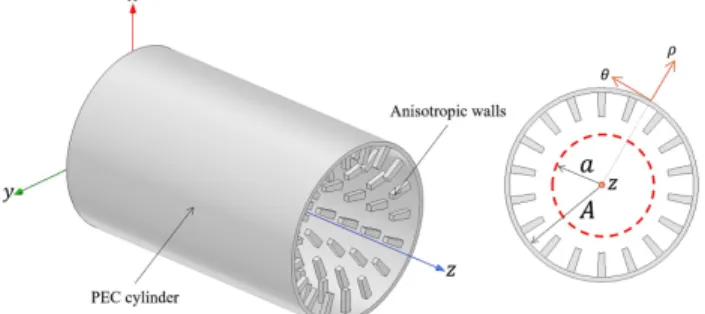
In this article, the studied waveguides are cylindrical waveguides with metamaterial walls and an invariance along the 𝑧-axis, see Fig. 1. Consequently, the electromagnetic field has an 𝑒!!!!
dependence, where 𝛾! is the propagation constant along the 𝑧-axis.
To characterize this kind of waveguides the MET is used [29]–[33]. Indeed, the metamaterial structuration – whose period is supposed small compared to the wavelength [25] – enables their study by computing equivalent anisotropic surface impedances. Therefore, the hybrid technique proposed, in this paper, is composed of the MET main program that solves the dispersion equation and a program in the open-source software GetDP [45] that computes the surface impedances.
2.1. The Modal Expansion Theory
In the cylindrical coordinate system, the 𝑍!! and 𝑍
!! surface impedances are defined by (1).
𝑍!! = −!!
!! !!!, 𝑍!
! = !!
!! !!!. (1)
These impedances are then injected in the dispersion equation (2) determined in [37] and [46] from Helmholtz’s equation and the anisotropic conditions.
𝑍! 𝑍! 𝐽!! 𝑢! ! −𝑍! 𝑍! 𝑘!𝐽! 𝑢! 𝑘! ! + 𝑍!𝑍! 𝑍!! + 1 𝑘!𝐽! 𝑢! 𝐽!! 𝑢! 𝑗𝑘! +𝑍! 𝑍! 𝑘! 𝑘! ! − 1 𝑚𝐽! 𝑢! 𝑢! ! = 0, (2)
where 𝑎 is the waveguide internal radius, 𝑢! = 𝑘!𝑎, 𝑍! the free space characteristic impedance, 𝐽! the Bessel function of order 𝑚, and 𝐽!! the derivative of the Bessel function 𝐽
!.
In [30]–[33], [37], it was pointed out that the 𝑍!! and 𝑍
!! surface impedances were dependent
on the 𝜑 incidence angle, defined with the relation (3). 𝜑 = arcsin 𝛽
𝑘! , (3)
where 𝛽 = −𝑗𝛾!, since only propagating modes were taken into account. In [33], the MET with
the 2-D FEM code has been extended to identify evanescent modes. Further research will be lead to characterize these modes with the 3-D FEM hybridized MET.
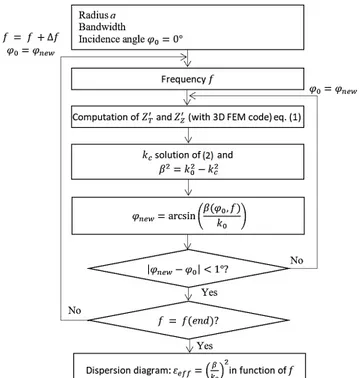
Consequently, the MET algorithm has to solve the dispersion equation with the recursive solution proposed in the Fig. 2. In the algorithm third step and for each 𝜑! computed angle, the 𝑍!! and 𝑍
Figure 2. Schematic algorithm to correct the 𝜑 incidence angle.
2.2. The 3D-Conformal Metamaterial Modelling
The analyzed unit cell is simplified in GetDP compared to HFSS solution since it allows non parallel periodic walls definition. This new 3-D unit cell is introduced in the next section. Then the code and its implementation in the MET are explained.
2.2.1. The 3D Unit Cell
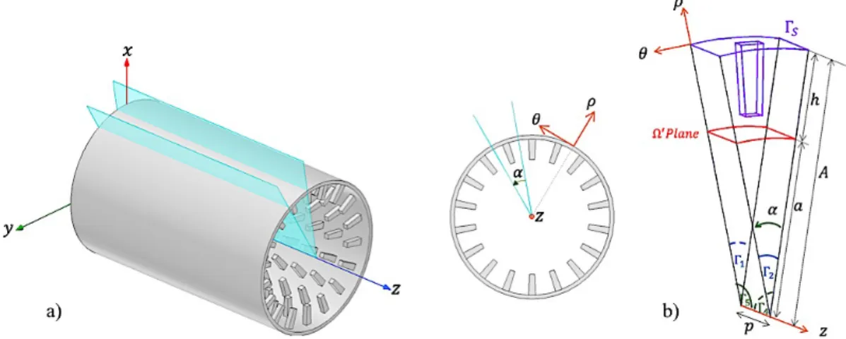
The waveguides under consideration are, obviously, periodical along the 𝑧-axis. In this paper, the metamaterial is not 𝜃-invariant anymore, compared to [31]–[33], but periodically set along this axis. The Fig. 3a) represents a 3-D metamaterial waveguide, with two planes that defines the angular periodicity of the metamaterial. Thus one periodic lattice can be isolated between these planes.
With the Fig. 3a) example, the 3-D metamaterial appears 18 times at a given longitunal position, thus the elementary lattice can be defined with an 𝛼 angle of 20°. The 3-D unit cell is represented on the Fig. 3b).
The lattice is isolated along the 𝑧-axis and 𝜃-axis. A periodical condition (4) is imposed between the Γ! and Γ! walls. A similar condition (5) is introduced between the Γ! and Γ! walls.
𝑈 𝜌, 𝜃, 𝑧 + 𝑝 !
! = 𝑈 𝜌, 𝜃, 𝑧 !!× exp −𝛾!𝑝 , (1)
𝑈 𝜌, 𝜃 + 𝛼, 𝑧 !
! = 𝑈 𝜌, 𝜃, 𝑧 !!× exp −𝑗𝑚𝛼 , (2)
where 𝑈 is a vector which could be the magnetic field 𝐻 or the electric field 𝐸, 𝑝 the distance between Γ! and Γ!, 𝛼 the angle between Γ! and Γ! (as defined on the Fig. 3b), and 𝑚 the mode order. A surface impedance can be defined on Γ!. In our cases, a PEC condition (the surface
impedance is equal to 0) is applied to this boundary. The 𝑍!! and 𝑍
!! (1) surface impedances are
computed on the Ω! plane. ℎ is the height to the Ω! plane (ℎ = 𝐴 − 𝑎).
Figure 3. a) 3-D metamaterial waveguide and b) the 3-D unit cell.
2.2.2. The New 3D-Finite Element Method Code
GetDP [45] means General environment for the treatment of Discrete Problems. This program is used to compute the equivalent surface impedances of the metamaterial. In its main file, the structure definition and the problem equations are specified.
The periodical conditions (4) between Γ! and Γ! and (5) between Γ! and Γ! are set in the code as the PEC condition on Γ!. The problem is solved by using a FEM formulation with edge
elements. The weak formulation (6) used is the following: ∇!𝐸 + 𝑘
!!𝐸 𝑣𝑑𝑉 = 0 !
, (3)
where 𝑣 is the test function, since the Galerkin method is used, and 𝑉 the volume described by the unit cell.
Thanks to a post processing operation, the electric and magnetic fields are returned in the whole structure. Besides a file is created with the values of these fields on the Ω! plane. This file
is used in the MET algorithm to compute the surface impedances.
2.2.3. Implementation of the 3D-Code in the MET
As explained before, the GetDP program is called on the third step in the MET algorithm. Hence, calling it each iteration can be a disadvantage, as it will take a significant computation time. Nevertheless, in the next part, it will be proven that even using this scheduling the time efficiency is better than using a commercial software.
3. RESULTS
To validate this method, this hybrid numerical technique is firstly applied to a waveguide with a 2-D metamaterial. This waveguide has corrugations along the 𝜃-axis [31], [36]. Subsequently, a 3-D metamaterial is studied: corrugation along the 𝑧-axis. Finally, the code is applied to a waveguide with a peak-structure metamaterial. All the dispersion diagrams are compared to those obtained with HFSS. All simulations were made with the same computer [Intel® Core™ i7-7700 CPU @ 3.60 GHz, 16 GB of RAM].
3.1. HFSS validation tool
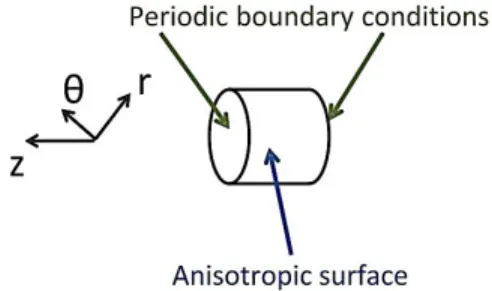
The eigenmode solver is chosen for this problem. A 3-D unit-cell, see Fig. 4, is created and periodic boundary conditions are added. A phase delay is included between these two walls, with a scan from 0° to 180°. This solver returns the resonance frequency of each solution (corresponding to a phase delay) and each mode. Then the propagation constant is computed using the phase delay and the 𝑝 distant between both walls. The analysis setup of the simulations changes with the tested waveguide.
Figure 4. Cylindrical representation of a waveguide with periodic boundary conditions and
anisotropic surface simulated in HFSS.
3.2. Waveguide with corrugations along the 𝜽-axis
The studied waveguide is represented on the Fig. 5a). The Figure 5b) shows the corrugation dimensions and the mesh obtained with GMSH-GetDP [45], [47].
Figure 5. a) Corrugated waveguide. The 3-D blue dashed section is used in HFSS, and the 3-D
red part is used in the MET b) represented with the mesh. The dimensions are 𝐴 = 100 mm, 𝑎 = 80 mm, ℎ = 20 mm, 𝑝 = 26.225 mm, 𝑤 = 20.98 mm, 𝑑 = 18.2 mm and 𝛼 = 20°.
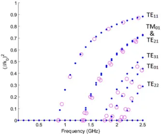
In [31], only 𝑚 = 0 order modes were displayed on the dispersion diagrams, and in [36] all modes were found, however the results between the method proposed and HFSS did not perfectly coincide. The Figure 6 represents the new dispersion diagrams obtained with the MET and the GetDP code (dots).
Both diagrams coincide and all modes are found. Consequently, the MET with the hybrid numerical technique is validated on this example. In HFSS, the adaptive solution for this waveguide is set to a maximum Δ𝑓 of 0.01%. Hence, with HFSS the simulation lasts three days, while with the MET it lasts 4 hours and 30 min. As explained before, the computation time with the MET with GetDP is quite longer than the MET with the 2-D FEM code [31] (10-min computation time), represented with triangles on the Fig. 6, due to the fact the software is called each iteration. Moreover, the frequency step is not the same. Indeed, in the MET the frequency is imposed then the incidence angle is evaluated to give the propagation constant. In HFSS, the incidence angle is imposed and the frequency evaluated.
Figure 6. Dispersion diagrams of the cylindrical waveguide with the corrugation presented in
Fig. 5a) obtained with the MET + 3-D FEM code (dots), the MET + 2-D FEM code [31] (triangles) and HFSS (circles).
3.3. Waveguide with corrugations along the 𝒛-axis
Corrugations along the 𝑧-axis are now inserted in a waveguide, see Fig. 7a).
Figure 7. a) Corrugated waveguide along the 𝑧-axis. The 3-D blue dashed section is used in HFSS, and the 3-D red part is used in the MET b) represented with the mesh. The dimensions are 𝐴 = 100 mm, 𝑎 = 80 mm, ℎ = 20 mm, 𝑝 = 26.225 mm, 𝑑 = 18.2 mm and 𝛼 = 30°.
The 𝛼 angle also conditions the number of metamaterial. In this example, 𝛼 = 30°, thus, there are twelve corrugations (360°/𝛼 = 12). The different dimensions and the mesh of the 3-D unit cell used in the MET are represented on the Fig. 7b).
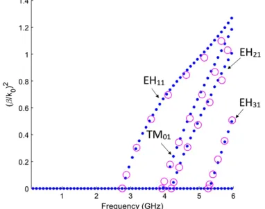
The algorithm is applied to this waveguide, and the dispersion diagrams are compared to HFSS ones on the Fig. 8. It took 40 min to obtain the dispersion diagrams with HFSS while with the MET only required a 21-min computation time. Therefore, the MET is still 2 time faster. It can be noted that the simulation on HFSS is drastically reduced compared to the previous case. As the matter of fact, for this waveguide Δ𝑓!"# = 0.05%, otherwise the simulation crashed due to a lack of memory space. The difference in the dispersion diagrams between both methods is small: the gap between the MET and HFSS increases with the 𝑚 order mode.
Figure 8. Dispersion diagrams of the cylindrical waveguide with the corrugation presented in
3.4. Waveguide with peak-structure metamaterial
Finally, a 3-D peak-structure metamaterial waveguide is tested with this hybrid numerical technique, see Fig. 9a). The Fig. 9b) (i) represents the dimensions and the mesh used in the MET and the Fig. 9b) (ii) displays the PEC part of the unit cell. As 𝛼 = 20°, there are 18 peak-structures in a cross-section.
Figure 9. a) Waveguide with the peak-structure metamaterial. The 3-D blue dashed section is
used in HFSS, and the 3-D red part is used in the MET b) represented with the mesh. The dimensions are (i) 𝐴 = 30 mm, 𝑎 = 15 mm, ℎ = 15 mm, 𝑝 = 10 mm; (ii) for the Γ! part (the PEC boundary) of the 3-D unit cell with 𝑑 = 8 mm, 𝛼 = 20°, and 𝑤 = 8 mm.
The dispersion diagrams of this waveguide are represented on the Fig. 10, the HFSS diagram is still represented with the circles, while the dots are associated with the MET diagram. Using the MET, the dispersion diagram was obtained in 1 hour and 16 min, compared to HFSS, with
Δ𝑓!"# = 0.01%, which lasts around three days. Again both dispersion diagrams coincide.
Figure 10. Dispersion diagrams of the cylindrical waveguide with the corrugation presented in
This new method has allowed plotting the whole dispersion diagrams of all kind of metamaterial waveguides. Moreover, the proposed method is at least twice as fast as the FEM commercial software for 0.05% error criteria on HFSS and 16 times faster for 0.01% error criteria.
CONCLUSION
In this article, the MET has been uploaded with a hybrid numerical technique using an open software: GetDP. The new algorithm has been successfully applied to three different waveguides: one with a 2-D metamaterial (a corrugation along the 𝜃-axis), and two with a 3-D metamaterial. As a consequence, the MET is now completely developed to characterize cylindrical waveguides with various metamaterials. Furthermore, the computation time is significantly reduced compared to commercial software.
The MET is currently used to reduce the cross-section of a cylindrical sensor working at the frequency band 6, 8 GHz. As a matter of fact, the reduction of the cross-section of sensor is mandatory to decrease its impact on the measurement of a testing antenna.
Moreover, the characterization of evanescent modes is also under development. Since, to characterize horn antenna with a mode-matching technique, these modes are also required. With the mode-matching technique, it will also be possible to deal with metamaterials that changes along the 𝑧-axis. Such kind of metamaterial are useful to improve the matching between the feeding access and the waveguide, or to avoid an abrupt termination of a horn antenna or an open-ended waveguide.
ACKNOWLEDGMENT
This work was made in collaboration between the CNES, MVG Industries, and the LAPLACE Laboratory. Moreover, the authors would like to thank Pablo Stuardo and Miguel Rojas Sanchez for their precious help in the development of the GetDP program.
REFERENCES
[1] Qi Wu, C.P. Scarborough, M.D. Gregory, D.H. Werner, R.K. Shaw, E. Lier "Broadband Metamaterial-Enabled Hybrid-Mode Horn Antennas, " in Proc. IEEE Antennas Propag. Soc. Int. Symp., Toronto, ON, Canada, Jul. 2010, pp. 1-4.
[2] C.P. Scarborough, Qi Wu, M.D. Gregory, D.H. Werner, R.K. Shaw, E. Lier, "Broadband Metamaterial Soft-Surface Horn Antennas," in Proc. IEEE Antennas Propag. Soc. Int. Symp., Toronto, ON, Canada, Jul. 2010, pp. 1-4.
[3] R. K. Shaw, E. Lier and C.-C. Hsu., "Profiled Hard Metamaterial Horns for Multibeam Reflectors," in Proc.
IEEE Antennas Propag. Soc. Int. Symp., Toronto, ON, Canada, Jul. 2010, pp. 1-4.
[4] E. Lier, R. K. Shaw, D.H. Werner, Qi Wu, C.P. Scarborough, M.D. Gregory, "Statuts on Meta-Horn Development - Theory and Experiments," in Proc. IEEE Antennas Propag. Soc. Int. Symp., Toronto, ON, Canada, Jul. 2010, pp. 1-4.
[5] P.-S. Kildal and E. Lier, "Hard Horns Improve Cluster Feeds of Satellite Antennas," Electron. Lett., vol. 24, no. 8, pp. 491-492, Apr. 1988.
[6] B. Thomas, "A Method of Synthesizing Radiation Patterns with Axial Symmetry," IEEE Trans. Antennas
Propag., vol. AP-14, no. 5, pp. 654-656, Sep. 1966
[7] E. Lier, "Review of Soft and Hard Horn Antennas, Including Metamaterial-Based Hybrid-Mode Horns,"
IEEE Trans. Antennas Propag. Mag., vol. 52, no. 2, pp. 31-39, Apr. 2010.
[8] J. G. Pollock and A. K. Iyer, "Below-Cutoff Propagation in Metamaterial-Lined Circular Waveguides,"
IEEE Trans. Microw. Theory Techn., vol. 61, no. 9, pp. 3169-3178, Sep. 2013.
[9] J. G. Pollock and A. K. Iyer, "Radiation Characteristics of Miniaturized Metamaterial-Lined Waveguide Probe Antennas," in Proc. 2015 IEEE Int. Symp. on Antennas Propag. USNC/URSI Nat. Radio Sci.
Meeting, Vancouver, BC, Canada, Jul. 2015, pp. 1734-1735.
[10] J. G. Pollock and A. K. Iyer, "Miniaturized Circular-Waveguide Probe Antennas using Metamaterial Liners,"
IEEE Trans. Antennas Propag., vol. 63, no. 1, pp. 428-433, Jan. 2015.
[11] J. G. Pollock and A. K. Iyer, "Experimental Verification of Below-Cutoff Propagation in Miniaturized Circular Waveguides Using Anisotropic ENNZ Metamaterial Liners," IEEE Trans. Microw. Theory Techn., vol. 64, no. 4, pp. 1297-1305, Apr. 2016.
[12] X. Ma, C. Huang, M. Pu, C. Hu, Q. Feng, and X. Luo, "Single-layer circular polarizer using metamaterial and its application in antenna," Microw. Opt. Technol. Lett., vol. 54, no. 7, pp. 1770–1774, 2012.
[13] Y. Huang, L. Yang, J. Li, Y. Wang, and G. Wen, "Polarization conversion of metasurface for the application of wide band low-profile circular polarization slot antenna," Appl. Phys. Lett., vol. 109, no. 5, p. 054101, 2016.
[14] H. L. Zhu, S. W. Cheung, X. H. Liu, and T. I. Yuk, "Design of polarization reconfigurable antenna using métasurfaces," IEEE Trans. Antennas Propag., vol. 62, no. 6, pp. 2891–2898, 2014.
[15] D. Schurig, J. J. Mock, B. J. Justice, S. A. Cummer, J. B. Pendry, A. F. Starr, D. R. Smith, "Metamaterial Electromagnetic Cloak at Microwave Frequencies," Science, vol. 314, no. 5801, pp. 977-980, Nov. 2006. [16] Y. Jia, Y. Liu, Y. J. Guo, K. Li, and S.-X. Gong, "Broadband polarization rotation reflective surfaces and
their applications to RCS reduction," IEEE Trans. Antennas Propag., vol. 64, no. 1, pp. 179–188, 2015. [17] J. J. Yang, Y. Z. Cheng, C. C. Ge, and R. Z. Gong, "Broadband polarization conversion metasurface based
on metal cut-wire structure for radar cross section reduction," Materials, vol. 11, no. 4, p. 626, 2018.
[18] Q. Zheng, C. Guo, H. Li, and J. Ding, "Broadband radar cross-section reduction using polarization conversion métasurfaces," Int. J. Microw. Wirel. Technol., vol. 10, no. 2, pp. 197–206, 2018.
[19] Y. Liu, K. Li, Y. Jia, Y. Hao, S. Gong, and Y. J. Guo, "Wideband RCS reduction of a slot array antenna using polarization conversion métasurfaces," IEEE Trans. Antennas Propag., vol. 64, no. 1, pp. 326–331, 2015.
[20] L. Zhang and T. Dong, "Low RCS and high-gain CP microstrip antenna using SA-MS," Electron. Lett., vol. 53, no. 6, pp. 375–376, 2017.
[21] K. Li, Y. Liu, Y. Jia, and Y. J. Guo, "A circularly polarized high-gain antenna with low RCS over a wideband using chessboard polarization conversion métasurfaces," IEEE Trans. Antennas Propag., vol. 65, no. 8, pp. 4288–4292, 2017.
[22] M. Long, W. Jiang, and S. Gong, "Wideband RCS reduction using polarization conversion metasurface and partially reflecting surface," IEEE Antennas Wirel. Propag. Lett., vol. 16, pp. 2534–2537, 2017.
[23] A. Sharma, D. Gangwar, B. Kumar Kanaujia, S. Dwari, and S. Kumar, "Design of a wideband polarisation conversion metasurface and its application for RCS reduction and gain enhancement of a circularly polarised antenna," IET Microw. Antennas Propag., vol. 13, no. 9, pp. 1427–1437, Jul. 2019, doi: 10.1049/iet-map.2018.6002.
[24] R. A. Shelby, D. R. Smith and S. Schultz, "Experimental Verification of a Negative Index of Refraction,"
Science, vol. 292, no. 5514, pp. 77-79, Apr. 2001.
[25] D. R. Smith, W. J. Padilla, D. C. Vier, S. C. Nemat-Nasser, and S. Schultz, "Composite Medium with Simultaneoustly Negative Permeability and Permittivity," Phys. Rev. Lett., vol. 84, no. 18, pp. 4184-4187, May 2000.
[26] V. G. Veselago, "The Electrodynamics of Substances with Simultaneously Negative Values of ε and µ," Sov.
Phys. Usp., vol. 10, no. 4, pp. 509-514, 1968.
[27] R. W. Ziolkowski and E. Heyman, "Wave Propagation in Media Having Negative Permittivity and Permeability," Phys. Rev. E, Stat. Phys. Plasmas Fluids Relat. Interdiscip. Top., vol. 64, no. 5, Dec. 2001, Art. no. 056625.
[28] Qi Wu, M. D. Gregory, D. H. Werner, P. L. Werner and E. Lier, "Nature-Inspired Design of Soft, Hard and Hybrid Metasurfaces," in Proc. IEEE Antennas Propag. Soc. Int. Symp., Toronto, ON, Canada, Jul. 2010, pp. 1-4.
[29] B. Byrne, N. Raveu, N. Capet, G. Le Fur and L. Duchesne, "Modal analysis of Rectangular Waveguides with 2D Metamaterials," Prog. Electromagn. Res. C, vol. 70, pp. 165-173, 2016, doi: 10.2528/PIERC16092904.
[30] B. Byrne, "Etude et Conception de Guides d'Onde et d'Antennes Cornets à Métamatériaux," Ph.D. dissertation, These de doctorat d'état, Univ. Toulouse, Toulouse, France, 2016.
[31] L. Kuhler, G. Le Fur, L. Duchesne, N. Raveu "The Propagation Characteristics of 2-D Metamaterial Waveguides Using the Modal Expansion Theory, " IEEE Trans. Microw. Theory Techn., vol. 66, no. 10, pp. 4319-4326, Oct. 2018.
[32] L. Kuhler, G. Le Fur, L. Duchesne, N. Raveu, "Modal Analysis of Cylindrical Waveguides with 2-D Metamaterial Wall," in Proc. META 2018 - The 9th Int. Conf.Metamaterials, Photonic Crystals Plasmonics, Marseille, France, 2018.
[33] L. Kuhler, N. Raveu, G. Le Fur, L. Duchesne, "Théorie Modale Élargie Appliquée aux Guides d’Onde Cylindriques à Métamatériaux," in Proc. XXIème Journées Nationales Microondes, Caen, France, 2019. [34] M. Warecka, R. Lech, and P. Kowalczyk, "Efficient Finite Element Analysis of Axially Symmetrical
Waveguides and Waveguide Discontinuities," IEEE Trans. Microw. Theory Tech., vol. 67, no. 11, pp. 4291– 4297, 2019.
[35] B. Byrne, N. Raveu, N. Capet, G. Le Fur and L. Duchesne, "Reduction of Rectangular Waveguide Cross-Section with Metamaterials: A New Approach," in Proc. 9th Int. Congr. Adv. Electromagn. Mater. Microw.
Opt. (METAMATERIALS), Oxford, U.K., Sep. 7-12, 2015, pp. 40-42.
[36] B. Byrne, N. Capet and N. Raveu, "Dispersion Properties of Corrugated Waveguides Based on the Modal Theory," in Proc. 8th Eur. Conf. on Antennas Propag., The Hague, The Netherland, Apr. 6-11, 2014, pp.1-3. [37] N. Raveu, B. Byrne, L. Claudepierre and N. Capet, "Modal Theory for Waveguides with Anisotropic Surface Impedance Boundaries," IEEE Trans. Microw. Theory Techn., vol. 64, no. 4 pp. 1153-1162, Apr. 2016.
[38] P.K. Verma, R. Kumar, M. Singh, "Design of a Shaped Omni Directional Circular Waveguide Antenna," in
Applied Electromagn. Conf. (AEMC), Kolkata, India, Dec. 14-16 2009.
[39] J. Tang, L. Fang, H. Cheng, "A Low Sidelobe and High Gain Omni-Directional COCO Antenna Array," in
Proc. Asia-Pacific Conf. Antennas Propag. (APCAP), Harbin, China, Jul. 26-29 2014.
[40] I. Güngör, A. Ünal, "Design of a Verticaly Polarized Omni-Directional Antenna at Ka-Band," in IEEE Int.
Symp. Antennas Propag. (APSURSI), Fajardo, Puerto Rico, 26 Jun.- 1 Jul. 2016.
[41] G. J. C. Granet, "Design of Corrugated Horns: a Primer," IEEE Trans. Antennas Propag., vol. 47, no. 2, pp. 76-84, Jul. 2005.
[42] P. J. B. Clarricoats, "Analysis of Spherical Hybrid Modes in a Corrugated Conical Horn," Electron. Lett., vol. 5, no. 9, pp. 189-190, May 1969.
[43] E. Lier, "Hybrid-mode horn antenna with design-specific aperture distribution and gain," in Proc. 2015 IEEE
Int. Symp. on Antennas Propag. USNC/URSI Nat. Radio Sci. Meeting, Columbus, OH, USA, Jun. 22-27
2003.
[44] P.J.B. Clarricoats, A. David Olver, "Corrugated Horns for Microwave Antennas," London, U.K., Peregrinus, 1984.
[45] P. Dular, C. Geuzaine, "GetDP Reference Manual: The Documentation for GetDP 3.0 A General Environment for the Treatment of Discrte Problems," Liège, Belgium, 2018.
Walls," Proc. Inst. Electrical Engineers, vol. 125, no. 10, pp. 929-932, Oct. 1978.
[47] C. Geuzaine and J.-F. Remacle, "Gmsh: A three-dimensional finite element mesh generator with built-in pre- and post-processing facilities," Int. J. for Numer. Methods Eng., vol. 79, no. 11, pp. 1309-1331, 2009.