Publisher’s version / Version de l'éditeur: Fire Technology, 14, 1, pp. 28-45, 1978-02
READ THESE TERMS AND CONDITIONS CAREFULLY BEFORE USING THIS WEBSITE. https://nrc-publications.canada.ca/eng/copyright
Vous avez des questions? Nous pouvons vous aider. Pour communiquer directement avec un auteur, consultez la
première page de la revue dans laquelle son article a été publié afin de trouver ses coordonnées. Si vous n’arrivez pas à les repérer, communiquez avec nous à PublicationsArchive-ArchivesPublications@nrc-cnrc.gc.ca.
Questions? Contact the NRC Publications Archive team at
PublicationsArchive-ArchivesPublications@nrc-cnrc.gc.ca. If you wish to email the authors directly, please see the first page of the publication for their contact information.
NRC Publications Archive
Archives des publications du CNRC
This publication could be one of several versions: author’s original, accepted manuscript or the publisher’s version. / La version de cette publication peut être l’une des suivantes : la version prépublication de l’auteur, la version acceptée du manuscrit ou la version de l’éditeur.
Access and use of this website and the material on it are subject to the Terms and Conditions set forth at
Calculation of the fire resistance of composite concrete floor and roof
slabs
Lie, T. T.
https://publications-cnrc.canada.ca/fra/droits
L’accès à ce site Web et l’utilisation de son contenu sont assujettis aux conditions présentées dans le site
LISEZ CES CONDITIONS ATTENTIVEMENT AVANT D’UTILISER CE SITE WEB.
NRC Publications Record / Notice d'Archives des publications de CNRC:
https://nrc-publications.canada.ca/eng/view/object/?id=df7d5f3f-2ddc-4ff1-a2cd-c31d90ba6a9d https://publications-cnrc.canada.ca/fra/voir/objet/?id=df7d5f3f-2ddc-4ff1-a2cd-c31d90ba6a9d
4 2 1
d
erQn
L O772
,
-
,-2
NATIONAL RESEARCH COUNCIL OF CANADACONSEIL NATIONAL D E RECHERCHES D U CANADA
03838
Calculation of the Fire
Resistance of Composite
Concrete Floor and
Reprinted from FIRE TECHNOLOGY Vol. 14, No. 1, February 1978
p. 28-45 and p. 50
DBR Paper No. 772 Division of Building Research
SOMMAIRE
La publication phsente une mQthode de calcul de la 14- sistance au feu des planchers et des dalles de toits composites.
A
partir de cette mhthode, on a Qtabli des formules simplespour le calcul de la rhsistance au feu et de 1'Qpaissetw mini- f-
male du bhton recouvrant l'armature dans les dalles de b6ton
..
ii arm6 et prhcontraint compodes d'une couche de bhton 1Qger-
" a t d'une couche de bQton ordinaire. La comparaison avec les rhsultats d'essais dhmontre la similarit& entre la r6- sistance au feu calculhe et celle obtenue h partir d'essais.Calculation o f the Fire Resistance of
-
Com~osite
Concrete Floor
a n d ~ o o f
Slabs
T. T. LIE
Division of Building Research
National Research Council of Canada
A calculation method is described for the determination of the fire resistance of composite floor and roof slabs. Using this method, simple approximate formulas are derived for the calculation of the thermal fire resistance and minimum cover thickness to the steel of reinforced and prestressed concrete slabs, consisting of two layers of concrete, one lightweight and one normal weight. Comparison with test results shows good agreement between cal- culated and experimental fire resistances.
I
N RECENT years, methods have been developed that have made it possible to solve many fire performance problems by calculation. In order to calculate the fire performance of a building element, it is necessary to know the temperature history of the element during exposure to fire. Methods exist for the calculation of the temperature history in various building elements, such as protected and unprotected steel columns, solid columns, and slabs. If the relevant material properties are known, ac- curate prediction of the temperatures in these elements during fire ex- posure is possible.In this study, a method is described for the calculation of the tempera- ture distribution in composite floor and roof slabs exposed to heating from below, under the conditions specified in ASTM E119.l As a particular case, slabs composed of two layers of concrete of various thicknesses, one lightweight and the other normal weight concrete, are considered. Their fire resistance, defined as the time to reach specific critical temperatures on the unexposed side of the slabs or on the steel in the slabs, is evaluated.
C A L C U L A T I O N M E T H O D
To calculate the temperature history of the slab, a finite difference method is used.2 I n this method, a cross-section of the slab is divided into a number of elementary layers (Figure 1). The thickness of the layers is
Copyright 1978, NATIONAL FIRE PROTECTION ASSOCIATION Printed in U.S.A
!
h
Floor and Roof Slabs 29
1
AX with the exception of the boundary layers, which are
W
Ax thick. Each Ilayer is represented by a point P,. The temperature in each elementary
i
layer is assumed to be uniform and equal to that of the representative point. At the top, the slab is covered by an asbestos pad of prescribed thickness.' I n Figure 1, a composite slab is shown consisting of two laminar concrete slabs, the lower made of concrete type nl and the upper of concrete type nz. The thickness of the (concrete),, slab is (Mi - l)Ax, that of the (con- crete),, slab is ( M , - Ml)ax.For each elementary layer a heat transfer equation is written for the time t = jAt, where j = 0, 1,2, .
.
.
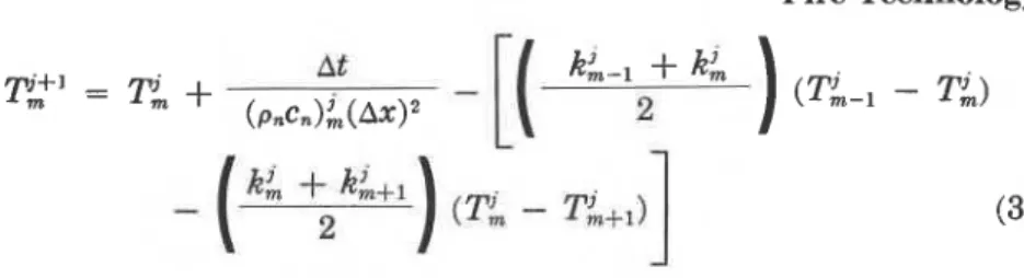
and At is an appropriate time increment. With the aid of these equations, the temperature of each layer can be suc- cessively evaluated for any time t = ( j+
1)At if the temperature a t the time t = jAt is known.The procedure of deriving the heat transfer equations for fire-exposed building elements is described in detail in previous ~ t u d i e s . ~ Therefore, the method of deriving these equations for the composite slab will not be discussed in this study; only the equations used for the calculation of the slab temperatures and information not yet dealt with in previous studies will be given.
E Q U A T I O N S F O R T H E B O U N D A R Y F I R E A N D S L A B
I n the derivation of the equations for the boundary fire and slab, it is assumed that the slab is exposed from below to a fire, the temperature of which increases according to the temperature-time curve specified in ASTM E119. This curve can be described approximately by the following expression:
The temperature a t the time t = ( j
+
1 ) ~ t of the boundary elementary layer of the slab, represented by the point pl can be given by:E Q U A T I O N S F O R T H E I N S I D E O F T H E S L A B For a n elementary layer represented by a point P,, located inside the slab but not a t the boundary of two layers of different material, the tem- perature a t the time t = ( j
+
1)At is given by:For a boundary elementary layer inside the slab, represented by the point PMl and composed partly of concrete type nl and partly of concrete type nz (Figure I ) , the temperature is given by:
E Q U A T I O N F O R T H E B O U N D A R Y S L A B A N D A S B E S T O S P A D
According to the specifications in ASTM E119, temperatures of the unexposed face of the slab should be measured under an asbestos pad of prescribed dimensions and properties. I n the calculation of these tem-
p - - - - - - BOUNDARY - - - M g ---- - - - ASBESTOS PAD - AMBIENT A I R
---- P ~ l + I --r ---- ---- - - -
-
-
- - - BOUNDARY - - - - - -.- - - ICONCRElEI - (CONCRETE)n "I 2 PI---- - - - - - - - - - - BOUNDARY - - - FIRE - (CONCRETEIn 1Floor and Roof Slabs 31
1
peratures, it is assumed that the heat flow through the slab and asbestos pad is one-dimensional. The equation that determines the temperature a t the time t = ( j
+
1 ) ~ t of the unexposed face of the concrete slab, i.e., the,
boundary slab and asbestos pad, is in this case:E Q U A T I O N F O R T H E I N S I D E O F T H E A S B E S T O S P A D
For the inside of the asbestos pad the temperature a t the time t =
I
j+
1)At of an elementary layer represented by a pointP,
is:E Q U A T I O N F O R T H E B O U N D A R Y A S B E S T O S P A D A N D A I R
At the boundary of the asbestos pad and air, heat is transferred from the pad to the air by convection and radiation. For the heat transferred by convection fiom the asbestos pad to the ambient air, the conventional expression given in Reference 4 has been used in the derivation of the heat transfer equations. I t follows that the temperature of the asbestos pad a t the boundary pad and ambient air a t the time t = ( j
+
1)At is given by:where
p i = density of asbestos:' 31.2 lb ft-3
d, = specific heat of asbestos:5 0.25 Btu lb-I OR-'
k: = thermal conductivity of asbestos:' 0.0316 Btu f t - I h-I OR-'
r
= coefficient expressing convective heat transfer from pad to air:'S T A B I L I T Y C R I T E R I O N O F T H E N U M E R I C A L S O L U T I O N
In order to ensure that any error existing in the solution a t some time level will not be arnpMed in the subsequent calculations, a stability cri- terion must be satisfied, which, for a selected value of Ax, limits the maxi- mum value of
at.
For fire-exposed composite slabs made of concrete, this criterion is:where
( p ~ ) , ~ , = the minimum value of the volumetric specific heat of con- crete met in practice: 13 Btu fC3 OR-'
k
,
,
,
= the maximum value of the thermal conductivity of concrete met in practice: 1.6 Btu ft-I h-I OR-Ih,,, = the maximum value of the coefficient of heat transfer at- tained in practice a t fire-exposed concrete surfaces: 147 Btu ft-2 h-' OR-'.
C A L C U L A T I O N P R O C E D U R E
With the aid of Equations 1 to 8, the temperatures a t any point of the composite slab can be calculated in successive steps for any time t = j A t . Initially, a t time t = 0, the slab and asbestos pad are at room tem- perature, here assumed to be 68" F. The first step is to calculate the tem- peratures in the various layers of the slab and asbestos pad for the time t = At. These are now used as initial temperatures for the calculation of the temperatures a t the time t = 2 A t . This process is repeated until the critical temperatures are exceeded. As critical temperatures, those speci- fied in ASTM El19 were selected. These are a temperature rise of 250" F a t the unexposed face of the concrete slab, a temperature of 800" F for prestressing steel, and a temperature of 1,100" F for reinforcing steel.
As can be seen in the equations, in order to calculate the temperatures of the slab, it is necessary to know the thermal properties of the con- cretes of which the slab is composed.
T H E R M A L P R O P E R T I E S
The thermal properties that mainly determine the temperature rise in the concrete are thermal conductivity and thermal capacity. In addition, there is an influence of the absorptivity of the material on the temperature. The thermal properties of concrete depend on the thermal properties of both the cement and the aggregate. Investigations6 show that the thermal properties of cement paste are not subject to large variations; the thermal
Floor and Roof Slabs 33
properties of aggregates, however, can vary over a wide range and therefore have substantial influence.
An important factor in determining the thermal properties of concrete is the molecular structure of the aggregate. For example, crystalline ma-
terials have higher conductivity than amorphous materials. I t is probable that the amount of material in the aggregate that undergoes endothermic reactions upon heating, such as dehydration, decomposition, and trans- formation, also has great influence on the thermal properties of the aggre- gate. In siliceous aggregates, for example, the presence of quartz, which transforms from a-quartz into p-quartz a t about 1,000" F, will cause an increase in the specific heat of the aggregate. In calcareous aggregates, the presence of magnesite and dolomite, which dissociate a t temperatures of 650 and 1,350" F respectively, will affect the thermal properties of the ag- gregate. During dissociation, heat is absorbed so that the presence of mag- nesite and dolomite should be beneficial for the fire resistance ,of the slab. Their effect on thermal properties, however, is not yet known precisely.
Because the composition of aggregates varies widely, a single set of thermal properties representative of those for all concretes cannot be given. I t is possible, however, to indicate extreme values for the thermal prop- erties, one high and one low value, and to select with the aid of existing data6- properties that will likely produce conservative results if used in fire resistance calculations. A study of these data shows that such values are obtained by averaging the extreme values. The values of the thermal conductivity and thermal capacity, which have been selected in this way for use in the calculations, are given in Tables 1 and 2 for normal weight concrete and lightweight concrete, respectively. For the absorptivity, a value of 0.9 derived from the data8 will be used.
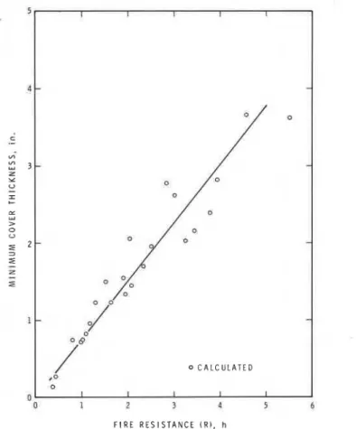
C O M P A R I S O N O F C A L C U L A T E D A N D T E S T R E S U L T S
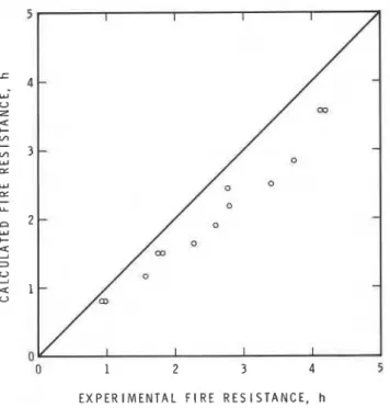
To verify the correctness of the heat transfer model and the values for the material properties, calculations were performed for a number of cases for which experimental information9 was available. A comparison between the calculated fire resistances, i.e., the time to reach a temperature rise of 250" F a t the unexposed face of the slab, and the experimental fire resistances is given in Figure 2. I t is seen that the calculated results are consistently lower than the experimental fire resistances. Lower values for the calcu- lated fire resistances, however, are to be expected because a somewhat con- servative method was used and the calculations were carried out for a dry slab, whereas the tested specimens contained moisture.
I t is possible to make corrections in the fire resistance for the moisture in the slab. According to ASTM E119, the standard moisture content of a test specimen is that corresponding to the equilibrium state of drying in
air of 50 percent relative humidity a t 73" F. If drying is difficult because of specimen size, it is permissible to test the specimen when, a t mid-depth
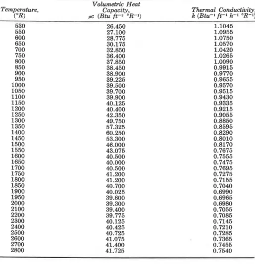
TABLE 1 . Thermal Properties of Lightweight Concrete Temperature, (OR) Volumetric Heat Capacity, oc (Btu ft-3 O R - 1 ) Thermal Conductivity, k (Btu ft-I h-I O R - l )
of the slab, the moisture content reaches a level corresponding t o that in equilibrium with air in the range of 50 t o 75 percent relative humidity. The standard describes a procedure for deriving the fire resistance for one moisture condition from that for other moisture conditions. Following this procedure, it can be derived that, depending on the thickness of the slab and its composition, the fire resistance increases by approximately 5
to 15 percent if the moisture content is increased from zero to that corre- sponding to 50 percent relative humidity a t mid-depth of the slab. If the moisture content is increased a t mid-depth from zero to that correspond- ing to 75 percent relative humidity, the fire resistance increases by approxi- mately 10 to 25 percent.
The moisture content a t mid-depth of the test specimens was that cor- responding to 75 percent relative humidity. To compare the calculated
Floor and Roof Slabs
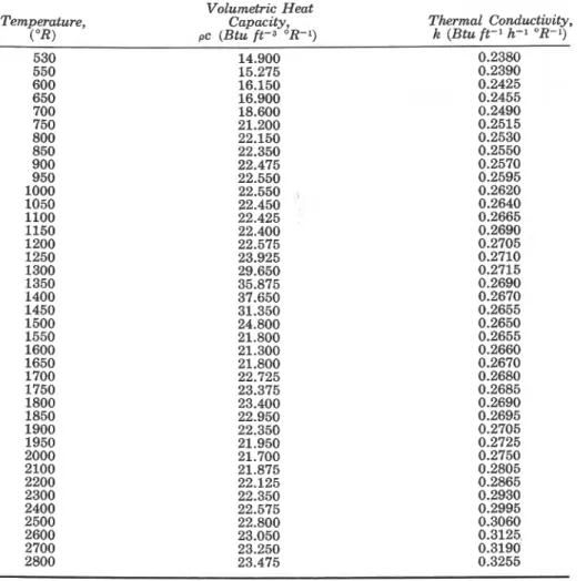
TABLE 2 . Thermal Properties of Normal Weight Concrete
Volumetric Heat I
Temperature, Capacity, (OR) oc (Btu ft-3 OR-1)
Thermal Conductivity, k (Btu-1 ft-1 h-1 OR-1) ,
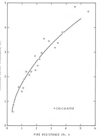
and experimental fire resistances, those calculated for the dry condition should be increased by an amount of the order of 15 to 20 percent. Fig- ure 3 shows this comparison, with the calculated results corrected by 20 percent to take into account the influence of moisture on fie resistance.
It is seen that, although most of the calculated fire resistances are still somewhat lower than the experimental, there is good agreement between theoretical and experimental results.
A P P R O X I M A T E F O R M U L A S
The fire resistance, in this case the time to reach the critical temperature on the unexposed face of the slab or on the steel in the slab, can be calcu- lated from Equations 1 to 8. The calculation procedure, however, is not
E X P E R I M E N T A L F l R E R E S I S T A N C E , h
Figure 2. Comparison of calculated and experimental fire resistances (not corrected for
moisture).
E X P E R I M E N T A L F l R E R E S I S T A N C E , h
Figure 3. Comparison of calculated and experimental fire resistances (corrected for mois-
Floor and Roof Slabs 37
suitable for general use in practice because it is elaborate and requires pro- gramming of the equations and computer processing. Therefore, a n at- tempt was made to derive simplified expressions that would be sufficiently accurate and allow the determination of fire resistance by hand calculation.
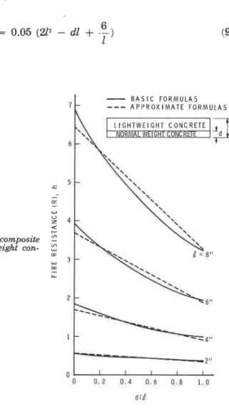
For this purpose, the fire resistance of composite slabs was calculated for a wide range of practical cases. Calculated results are given in Figures 4
to 9. In Figure 4, the fire resistance, based on attainment of a temperature
I
rise of 250" F a t the unexposed surface between concrete and asbestos pad,
'
is plotted as a function of the ratio d/l, where d is the thickness of the lower
layer and
I
the total thickness of the slab. The curves in this figure are forslab thicknesses of 2, 4, 6, and 8 in., respectively. It is assumed that the
lower layer of the slab is composed of no-a1 weight concrete and the up- '
per layer of lightweight concrete. The solid lines give the fire resistances derived from the basic Equations 1 to 8. These lines can be described ap- proximately by the expression:
Figure 4 . Fire resistance of composite
slabs (lower layer of normal weight con- crete).
-
B A S I C F O R M U L A S 7 ----
A P P R O X I M A T E F O R M U L A Swhere
R
= fire resistance of the slab, hI = thickness of the slab, in.
d = thickness of the lower layer, in.
Results obtained from this expression are given by the dashed lilies in Figure 4.
In Figure 5, similar curves are given for the case where the lower layer is composed of lightweight concrete and the upper layer of normal weight concrete. In this case, the fire resistances calculated from the basic equa- tions can be approximated by the expression:
where R, 1, and d have the same meaning as in Equation 9.
In addition to exceeding a temperature rise of 250" F a t the unexposed surface, floor and roof assemblies may also fail because of excessive tem- perature rise of the prestressing or reinforcing steel in the slab. The critical steel temperature, i.e., the temperature a t which the steel can no longer support the loading, depends on several factors, such as loading and end conditions.1° In this paper, the values specified by ASTM El19 for un- restrained floor and roof slabs are selected as critical temperatures. These are 800" F for prestressing steel and 1,100" F for reinforcing steel.
I t is assumed that the slab fails structurally a t the time that the tem- perature of the steel in the slab exceeds one of the previously mentioned
-
B A S I C F O R M U L A S
Figure 5. Fire resistance of composite slabs (lower layer of lightweight con- crete).
Floor and Roof Slabs 39
1
I I I I I 0 0 -/
-/
- 0 /O -1
- - 0 C A L C U L A T E D 1 I I I I F I R E R E S I S T A N C E ( R I , hFigure 6. Minimum cover thickness to prestressing steel as a function of fire resistance (lower layer of normal weight concrete - unrestrained assembly classification).
critical temperatures. In fire tests, the steel temperatures a t which the specimen actually fails may differ from the selected critical temperatures. In particular, if the specimen is restrained against thermal expansion, which will be beneficial for its fire resistance, the failure temperatures will likely be higher. The chosen critical temperatures are expected to be representa- tive of those of unrestrained slabs, but conservative in the case of restrained slabs.
By calculating the temperature distribution in the slab, the depth a t which critical temperatures are attained when the unexposed surface tem- perature reaches 250" F can be determined. By providing the steel with a concrete cover that is a t least equal in thickness to this depth, the attain- ment of steel temperatures in excess of the critical temperatures can be prevented.
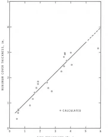
The minimum cover thickness to obtain a certain fire resistance is shown for a large number of cases in Figures 6 to 9. Cover thickness is here defined as the distance between the fire-exposed surface and the cen-
5 1 I I t I
-
- 0-
- - - - -7
0 C A L C U L A T E D .o a I 1 b I 1 F I R E R E S I S T A N C E ( R ) , hFigure 7 . Minimum cover thickness to reinforcing steel as a function of fire resistance (lower layer of normal weight concrete - unrestrained assembly classification).
ter of the prestressing or reinforcing steel. The curves in Figure 6 give the minimum cover thickness for prestressed concrete slabs of which the lower layer is composed of normal weight concrete. For such slabs the depend-' ence of minimum cover thickness on fire resistance desired is given approxi- mately by the relation:
c =
d m (11)where
C = minimum cover thickness, in.
R = fire resistance desired, h.
Figure 7 shows the minimum cover thickness to reinforcing steel when the lower layer is composed of normal weight concrete. It is given approxi- mately by the relation:
C = 0.75 R (12)
where C and R have the same meaning as that in Equation 11.
In Figures 8 and 9, the calculated minimum cover thicknesses are shown for slabs of which the lower layer is composed of lightweight concrete.
Floor and Roof Slabs
F I R E R E S I S T A N C E I R ) , h
Figure 8. Minimum cover thickness to prestressing steel as a function of fire resistance (lower layer of lightweight concrete - unrestrained assembly classification).
For prestressed concrete slabs (Figure 8), the relation between minimum cover thickness C and desired fire resistance R is given approximately by the expression:
C = 0.6 R
+
0.4 (13)and for reinforced concrete slabs (Figure 9), by the expression:
E X A M P L E
It might be useful to illustrate in an example the use of the approximate formulas for the determination of the fire resistance and minimum cover thickness of composite slabs. A reinforced concrete composite slab is con- sidered, consisting of a lower layer of 3%-in. thick normal weight concrete and an upper layer of lightweight concrete 2% in. thick. The moisture content of the slab is equal to that corresponding to equilibrium with air of 75 percent relative humidity a t room temperature (approximately 70" F).
The is to calculate the thermal fire resistance and the required mini-
mum cover thickness to prevent excessive temperature rise and failure of
the steel before the slab fails thermally on the unexposed surface. .
According to Equation 9, the thermal fire resistance of the slab is:
where
I = 6 in. (thickness of slab)
d = 3.5 in. (thickness of lower layer).
Floor and Roof Slabs 43
This is the thermal fire resistance for the dry slab. As suggested previ- ously, for a moisture condition corresponding to equilibrium with air of 75 percent relative humidity a t room temperature, the fire resistance may be derived by increasing the fire resistance for the dry slab by 20 percent. Thus, the fire resistance of the slab under consideration is 2.6
+
(0.2X2.6) = 3 . 1 2 h o r 3 h a n d 7 m i n . Inatest,afirer&tanceof3hand I
24 min was found.
The minimum cover thickness to prevent failure of the reinforcing steel before the temperature of the unexposed face reaches the failure
tem-
, perature (i.e., before the elapse of an exposure time of 3.12 h) can be cal- culated &om Equation 13. According to this equation, the minimum cover,
thickness is:C = 0.75 R
or C = 0.75 X 3.12 = 2.34 in.
Thus the required minimum thickness of concrete between the exposed face of the slab and the center of the steel is 2.34 in.
S U M M A R Y
A numerical calculation method is described for the determination of the fire resistance of composite floor and roof slabs. Using this method, simple approximate formulas are derived for the calculation of the thermal fire resistance and minimum cover thickness to the steel of reinforced and prestressed concrete slabs, consisting of two layers of concrete, one light- weight and one normal weight.
Comparison with test results shows good agreement between calculated and experimental fire resistances, although calculated values are on the average somewhat more conservative.
R E F E R E N C E S
"Standard Methods of Fire Tests of Building Construction and Materials," American Society for Testing and Materials, Designation E119-73, Part 18, 1974,
pp. 610-628.
2Dusinberre, G. M., Heat Transfer Calculations by Finite Differences (International Textbook Company, Scranton, Pennsylvania, 1961), p. 293.
aLie, T. T., "Temperature Distributions in Fire-Exposed Building Columns,"
Journal of Heat Transfer, A S M E , Vol. 99, No. 1 (February 1977), pp. 113-119. %piers, H. M., Technical Data on Fuel (6th Edition, World Preea Conference, London, 1961), p. 66.
'
=Liley, P. E., "Physical and Chemical Data" in Chemical Engineer's Handbook (McGraw-Hill, New York, 1963), p. 133.
Warmathy, T. Z., "Thermal Properties of Concrete a t Elevated Temperatures,"
A S T M Journal of Materials, Vol. 5 , No. 1 (March 1970), pp. 47-74.
'Harmathy, T. Z., "Thermal Properties of Selected Masonry Unit Concretes,"
Journal of the American Concrete Institute, Vol. 70, No. 2 (February 1973), pp. 132-142. UGilmour, M. S. et al., "Heat Transmission" in Chemical Engineer's Handbook (McGraw-Hill, New York, 1963), pp. 35-36.
gAbrams, M. S. and Gustaferro, A. H., "Fire Endurance of Two-Course Floors and Roofs," Journal of the American Concrete Institute, Vol. 66, No. 2 (February 1969), pp. 92-102.
'OLie, T. T., Fire and Buildings (Applied Science Publishers Ltd., London, 1972). pp. 168-176.
A P P E N D I X A - A P P R O X I M A T E F O R M U L A S This appendix gives a summary of the approximate formulas for the calculation of the thermal fire resistance and minimum cover thickness to the steel of composite floor and roof slabs. Considered are reinforced and prestressed concrete slabs consisting of two layers of concrete. One layer is lightweight concrete, the other layer is normal weight concrete. Formulas are given for both cases, i.e., the lower layer is made of lightweight con- crete or it is made of normal weight concrete.
The thermal fire resistance is defined as the time to reach a tempera- ture rise a t the unexposed face of the slab of 250" F. The minimum cover thickness is the thickness of concrete between the exposed face and the center of the steel necessary to prevent the steel temperature from exceed- ing 800" F for prestressing steel and 1,100" F for reinforcing steel. The fire resistance values are for dry slabs or those close to the dry condition. For a moisture condition corresponding to that in equilibrium with air of 50 percent or more but less than 75 percent relative humidity a t 73" F, it is suggested that 10 percent be added to the fire resistance for the dry con- dition and 20 percent for a moisture condition corresponding to 75 percent or higher relative humidity.
The formulas are valid for fire resistances in the range of 20 min to 5 h.
Fire Resistance
where
R = fire resistance of slab, h
1 = thickness of slab, in. d = thickness of lower layer, in. Moisture Correction
Add 10 percent for a moisture condition corresponding to 50 to <75 per- cent relative humidity. Add 20 percent for a moisture condition corre- sponding to 2 7 5 percent relative humidity.
Minimum Cover Thickness
Prestressed concrete: C = d 4 R - 1
Floor and Hoof Slabs
where
C = minimum cover thickness, in. R = fire resistance of slab, h.
LOWER LAYER OF LIGHTWEIGHT CONCRETE
Fire Resistance
where
R = fire resistance of slab, h 1 = thickness of slab, in.
d = thickness of lower layer, in.
Moisture Correction
\
Add 10 percent for a moisture condition corresponding to 50 to <75 percent relative humidity. Add 20 percent for a moisture condition cor- responding to 2 7 5 percent relative humidity.
Minimum Cover Thickness
Prestressed concrete: C = 0.6R
+
0.4 Reinforced concrete: C = 0.5R whereC = minimum cover thickness, in. R = fire resistance of slab, h.
A P P E N D I X B - N O M E N C L A T U R E
c = specific heat, Btu 1b-l OR-1
C = minimum cover thickness, in. d = thickness of lower layer, in.
h = coefficient of heat transfer a t fire-exposed surface, Btu ftT2 hdl OR-l
j = 0 , 1 , 2 , .
.
.
k = thermal conductivity, Btu h-1 ft-I OR-' 1 = thickness of slab, in.
p = point
R = fire resistance of slab, h
t = time, h
T = temperature, OR x = coordinate, ft GREEK LETTERS
r
= coefficient expressing convective heat transfer from pad to air: 0.1823Btu f t - 2 h-1 OR-1.25 A = increment
= emissivity
p = density
u = Stefan-Boltzmann constant, 0.1713
x
Btu h-I ftf2= of asbestos
= of the fire
%, .I[, rrz,
.
. .
= at a point in the m-th, M-th, MI-th, Mn-th.
.
.
= ele-mentary layer
,nax = maximum value of
,in = minimum value of
,,
.,,
,,,
. .
.
= concrete type = initialACKNOWLEDGMENT: The author wishes to thank G. Williams-Leir, who gave valu-
able advice during the development of the calculation method. This paper is a con- tribution from the Division of Building Research of the National Research Council of Canada and is published with the approval of the Director of the Division.