Publisher’s version / Version de l'éditeur:
Canadian Building Digest, 1985-07-01
READ THESE TERMS AND CONDITIONS CAREFULLY BEFORE USING THIS WEBSITE. https://nrc-publications.canada.ca/eng/copyright
Vous avez des questions? Nous pouvons vous aider. Pour communiquer directement avec un auteur, consultez la
première page de la revue dans laquelle son article a été publié afin de trouver ses coordonnées. Si vous n’arrivez pas à les repérer, communiquez avec nous à [email protected].
Questions? Contact the NRC Publications Archive team at
[email protected]. If you wish to email the authors directly, please see the first page of the publication for their contact information.
NRC Publications Archive
Archives des publications du CNRC
For the publisher’s version, please access the DOI link below./ Pour consulter la version de l’éditeur, utilisez le lien DOI ci-dessous.
https://doi.org/10.4224/20328703
Access and use of this website and the material on it are subject to the Terms and Conditions set forth at
Factors affecting sound transmission loss
Warnock, A. C. C.
https://publications-cnrc.canada.ca/fra/droits
L’accès à ce site Web et l’utilisation de son contenu sont assujettis aux conditions présentées dans le site
LISEZ CES CONDITIONS ATTENTIVEMENT AVANT D’UTILISER CE SITE WEB.
NRC Publications Record / Notice d'Archives des publications de CNRC:
https://nrc-publications.canada.ca/eng/view/object/?id=6f04ffd7-4531-4ea2-ada6-3df32c9674ee https://publications-cnrc.canada.ca/fra/voir/objet/?id=6f04ffd7-4531-4ea2-ada6-3df32c9674eeCanadian Building Digest
Division of Building Research, National Research Council Canada
CBD-239
Factors Affecting Sound Transmission Loss
Please note
This publication is a part of a discontinued series and is archived here as an historical reference. Readers should consult design and regulatory experts for guidance on the applicability of the information to current construction practice.
Originally published July 1985 A.C.C. Warnock
Abstract
The sound transmission losses of single and double layer walls and floors are determined by the physical properties of the component materials and the methods of assembly. These factors are discussed.
Introduction
The sound transmission loss of a partition or a floor are determined by physical factors such as mass and stiffness. In a double layer assembly, such as gypsum wallboard on wood or metal framing, the depth of air spaces, the presence or absence of sound absorbing material, and the degree of mechanical coupling between layers critically affect sound transmission losses and therefore the sound transmission class (STC). (These terms were discussed inCanadian Building Digest 236.1) An understanding of these factors can lead to improved design and fewer errors. Small changes in the arrangement of materials can yield large changes in STC with little or no increase in cost.
Three interacting physical factors are important in determining whether an occupant of a multi-family dwelling is bothered by noise from neighbours. These are the sound transmission losses of party walls or floors, the level of noise generated in neighbouring homes, and the level of background sound in the occupant's own home. The last two factors can vary widely and one has to select a value of STC that will provide protection for most situations and accept those cases where annoyance is caused by an unusually noisy neighbour or unusually low background sound levels. If the level of background sound is high enough, intruding sounds will be masked and will not be detectable. On the other hand, if the background noise is excessively high, it can interfere with sleep, relaxation, and even conversation. Experience around the world has shown that for occupants of multi-family dwellings to enjoy a reasonable degree of acoustical privacy, the effective STC between dwelling units should be at least 55. Values in excess of STC 60 can be achieved with typical building materials without resorting to extreme designs,
although care is needed during the design and construction processes. Mass Law
The most important physical property controlling the airborne sound transmission loss through an assembly is the mass per unit area of its component layers. The "mass law" is a theoretical rule that applies to most materials in certain frequency ranges. It can be approximated as TL
where TL is the random incidence transmission loss of the layer; msis the mass per unit area, kg/m²; and f is the frequency of the sound wave, Hz. The mass per unit area, ms, is the product of the material density and its thickness. Values of ms for 1 mm thicknesses of common materials are presented in Table 1.
The mass law equation predicts that each time the frequency of measurement or the mass per unit area of a single layer wall is doubled, the transmission loss increases by about 6 dB. To increase the sound transmission loss of a partition by 12 dB at all frequencies, therefore, the mass per unit area must be increased by a factor of 4; an increase of 18 dB requires an
increase by a factor of 8 and so on. Mass per unit area can be increased by increasing thickness or by selecting a more dense material. A single layer of poured concrete 150 mm thick gives an STC of about 55. Layers of this weight are generally the practical limit in normal construction. If a higher STC value than this is necessary, and it often is in high quality construction, it is not economical to continually double the wall or floor thickness to achieve it. Double layer
assemblies are a more practical way of getting high STC values without excessive weight. Effects of Stiffness
Sound transmission losses of partitions and floors are also influenced by stiffness. Transmission loss graphs for stiff materials show dips in particular frequency ranges where the sound
transmission losses are reduced below those expected from mass law. This is called the coincidence effect and often leads to a reduced STC rating. Materials with very low stiffness such as sheet lead effectively do not show coincidence dips. Coincidence frequencies for different materials occur in different parts of the acoustical spectrum, sometimes outside the normal range used in building acoustics. The coincidence or critical frequency, fc, for a given material may be calculated from:
fc
= A/t (2)
where A is a constant for each material under consideration and t is the material thickness, mm.
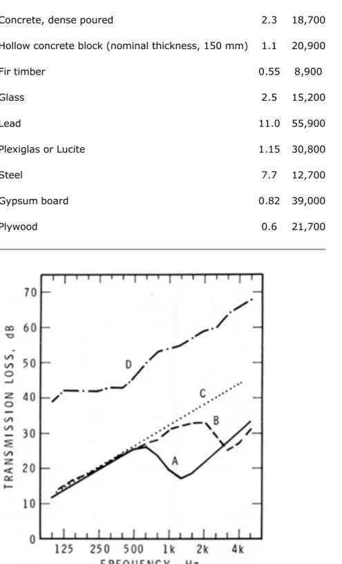
Table 1 gives values of A that permit the calculation of the coincidence frequency for different materials. For example steel has an A value of 12,700 Hz-mm and Equation 2 shows that a 5 mm sheet of steel has a coincidence frequency of 2540 Hz. Similarly, a layer of concrete 100 mm thick would have a coincidence dip at 187 Hz. Figure 1 shows idealized transmission loss curves, including coincidence dips, for some common materials. Materials A, B, and C all have the same mass per unit area but quite different STC ratings because of differing coincidence effects. Because the critical frequencies of concrete and plywood in the thicknesses commonly used fall in the frequency range that is important in building acoustics (100 to 4000 Hz), they are particularly vulnerable to STC reductions due to the effects of coincidence. For gypsum wallboard the coincidence frequency is quite high and the effect on the STC is usually less. The depth of the coincidence dip is determined by the energy losses in the material and at its edges where it is in contact with other materials in the supporting structure. The greater the energy losses, the shallower the coincidence dip and the less the effect on the STC.
Table 1. Surface Mass, ms, for 1 mm Thickness and Constant, A, for Calculation of
Critical Frequency, fc, of Some Common Building Materials
Material ms kg/m² per mm A Hz-mm
Aluminium 2.7 12,900
Concrete, dense poured 2.3 18,700
Hollow concrete block (nominal thickness, 150 mm) 1.1 20,900
Fir timber 0.55 8,900 Glass 2.5 15,200 Lead 11.0 55,900 Plexiglas or Lucite 1.15 30,800 Steel 7.7 12,700 Gypsum board 0.82 39,000 Plywood 0.6 21,700
Figure 1. Transmission losses of typical single-leaf walls, A: 16 mm plywood, 10 kg/m², STC 21; B: 13 mm wallboard, 10 kg/m², STC 28; C: 1.3 mm steel, 10 kg/m², STC 30; D: 100 mm concrete, 235 kg/m², STC 52.
When two layers of material such as wallboard are glued firmly together, they behave like a single thick layer with an associated lowering of the coincidence frequency. If the layers are
only held together loosely (with screws for example) so that they can slide over each other to some extent during bending motions, then the coincidence frequency does not move to lower frequencies and the friction between the layers can introduce some extra energy losses. Double Layer Assemblies
When lightweight construction and high STC values are desired, double layer constructions must be used. These can be very effective but introduce additional effects that must be appreciated if double layer designs are to be successful. Important factors, in addition to the masses of the component layers, are the depth of the air space, the use of sound absorbing materials within the air spaces, and the rigidity of the mechanical coupling between the layers. The ideal double layer assembly has no rigid mechanical connection between its two surfaces. In a double layer wall or floor the air trapped between the two layers acts as a spring and a resonance, called the mass-air-mass resonance, occurs at a frequency fmamgiven by:
(3)
where m1, m2are the surface masses of the layers, kg/m²; and D is the distance between the layers, mm. The larger the air space or the heavier the materials, the lower the frequency at which resonance occurs. At frequencies below the resonance frequency, the layers are coupled by the air in the cavity and the TL is that due to the sum of their masses. Close to the
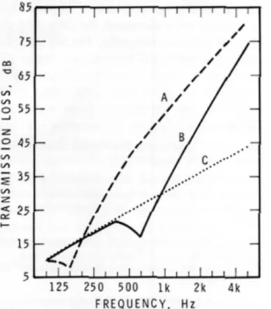
resonance frequency, however, the transmission losses are usually lower than this. Above the resonance frequency, the sound transmission loss increases much more rapidly than mass law predictions for the sum of the masses. Figure 2 gives an example of the benefits to be obtained by increasing the air space between the two layers of a wall. Generally, partitions should be designed so that the mass-air-mass resonance is below 80 Hz.
absorbing material in the cavity and no rigid mechanical connections between the faces. A has an airspace of 100 mm, a resonance dip at 135 Hz, and an STC of 29; B has an airspace of 5 mm, a resonance dip at 630 Hz, and an STC of 24. Curve C represents mass law predictions for a single 1 mm steel sheet and has an STC of 28.
Standing wave resonances between the layers of a double layer wall or floor occur at relatively high frequencies and the sound transmission losses can be further reduced by them. The negative effects of most of these resonances can be reduced by the addition of sound absorbing material inside the cavities. For normal wall thicknesses (around 100 mm) the density and the thickness of the sound absorbing material is not a very important factor. Increasing the thickness beyond about 75 mm has little effect on the STC rating, although, for floors or walls that are significantly thicker than normal, it becomes more important to use thicker layers of glass fibre. The type of glass fibre or mineral wool insulation normally used for thermal purposes absorbs sound well and is quite adequate for use inside double layer walls as a sound absorbing material.
Gypsum Board Walls
The mechanical connection between the layers of wallboard can be reduced by the use of staggered wood studs, separate rows of wood studs, or a single row of wood studs with resilient metal furring strips to support the wallboard layers independently of each other. Non-load-bearing steel studs are usually resilient enough to provide adequate mechanical
decoupling between the layers. Good results have also been obtained using 150 mm load-bearing steel studs in conjunction with resilient channels. Table 2 gives some representative STC values for typical constructions. The presence of the sound absorbing material increases the STC by about 8 points relative to the same wall without sound absorbing material. The thickness of the wallboard is not specified in the table since it is only a guide. Walls with 16 mm board would be better than those with 13 mm board by a few points. The table shows that STC values of 60 or more can be obtained if the air space is large enough and enough wallboard is used. Such values have been measured in buildings as well as in laboratories.
Table 2. STC Ratings for Walls Formed From Two Layers of Wallboard*
Number of Layers of Wallboard on Each Wall Surface
Wall construction 1+1 1+2 2+2
38 x 89 mm wood studs with resilient steel channels on one side 48 [40] 52 [44] 56 [52] Staggered 38 x 89 mm wood studs 50
[41]
53 [47]
55 [52] Double row of 38 x 89 mm wood studs with small gap
between them 57 [46] 60 [52] 63 [57] 90 mm steel studs 45 [39] 49 [45] 56 [50]
150 mm load-bearing steel studs with resilient metal
channels on one side 58 60 63
*Values not in brackets are for walls filled with sound absorbing material. Values in brackets are for walls without sound absorbing material.
In contrast to the values in the table, the common internal partition used in single family homes with drywall attached directly to both sides of the wood studs has an STC rating of about 33. The addition of sound absorbing material in this wall increases its rating by about only 3 points, because the sound energy is transmitted directly from one layer of wallboard to the other through the studs. The sound absorbing material in the cavity is of much less benefit than it would be if the layers were decoupled, in which case most of the sound would be transmitted through the air in the cavity. Rigid mechanical connections are the acoustical equivalent of an electrical short circuit or a thermal bridge in an insulated wall and should be avoided.
Concrete Block Walls
Concrete block walls commonly have wallboard applied to each face as a finishing material. Resilient connections and sound absorbing material in cavities are as important in block walls as they are in wood or steel frame construction. The mass-air-mass resonance is also
important. If the air gap behind the wallboard is too small, the sound transmission losses can be reduced relative to the unfinished wall. For a single layer of wallboard attached to a concrete block wall, the air space should be greater than 60 mm to meet the 80 Hz criterion previously noted. For a double layer of wallboard, the space may be as small as 35 mm. These air spaces are larger than those typically used in concrete block walls where relatively thin wood furring strips are often used to attach the wallboard. Even using adhesive to attach wallboard directly to concrete can result in a thin film of air a few mm in thickness trapped behind the wallboard and a deleterious mass-air-mass resonance. Reduced sound transmission losses caused by the mass-air-mass resonance are often the cause of a low STC for a potentially good concrete block wall. An increase in the air gap of just a few centimetres can increase the STC considerably. Some concrete blocks are slightly porous so that the effective thickness of the air layer behind the wallboard is greater than its physical dimensions and the mass-air-mass resonance is lower than expected. This characteristic can only be verified by acoustical testing, however. Sound transmission class ratings for some concrete block constructions can be found in references 2, 3 and 4. STC ratings of 60 or more can readily be achieved with a concrete block wall if it is correctly designed and constructed.
Flanking Transmission
In laboratory measurements of airborne sound transmission, the only significant sound
transmission path between the test rooms is through the test partition or the test floor itself. In real buildings, however, sound travels between suites indirectly by way of the surrounding constructions as well as directly through the common wall or floor assembly. These less obvious paths for the sound are called flanking paths and, in a poor design, they can transmit more sound energy than the direct path through the common wall or floor. All of these paths
comprise a system that must be considered as a whole so that assemblies built in the field can attain values close to those in laboratory tests. Floors are particularly prone to increased impact sound transmission because of flanking transmission through the supporting structure. Flanking transmission is beyond the scope of this Digest, however. If the physical factors that control the STC of partitions and floor assemblies are understood, the principles can be applied to all transmission paths. Further information can be found in reference 5.
References
1. Warnock. A.C.C. Fundamentals of building acoustics.Canadian Building Digest 236, 1985.* 2. Northwood, T.D. and Monk, D.W. Sound transmission loss of masonry walls: Twelve-inch
lightweight concrete blocks with various surface finishes. Building Research Note 90, April 1974.**
3. Northwood, T.D. and Monk, D.W. Sound transmission loss of masonry walls: Twelve-inch lightweight concrete blocks comparison of latex and plaster sealers. Building Research Note 93, September 1974.**
4. Warnock, A.C.C. and Monk, D.W. Sound transmission loss of masonry walls: Tests on 90, 140, 190, 240 and 290 mm concrete block walls with various surface finishes.Building Research Note 217, June 1984.*
5. ASTM E497-76. Standard recommended practice for installation of fixed partitions of light frame type for the purpose of conserving their sound insulation efficiency. American Society for Testing and Materials, 1916 Race Street, Philadelphia, PA, 19103, U.S.A.
Available from Division of Building Research, National Research Council of Canada. Photocopies available from CISTI.