READ THESE TERMS AND CONDITIONS CAREFULLY BEFORE USING THIS WEBSITE. https://nrc-publications.canada.ca/eng/copyright
Vous avez des questions? Nous pouvons vous aider. Pour communiquer directement avec un auteur, consultez la première page de la revue dans laquelle son article a été publié afin de trouver ses coordonnées. Si vous n’arrivez pas à les repérer, communiquez avec nous à PublicationsArchive-ArchivesPublications@nrc-cnrc.gc.ca.
Questions? Contact the NRC Publications Archive team at
PublicationsArchive-ArchivesPublications@nrc-cnrc.gc.ca. If you wish to email the authors directly, please see the first page of the publication for their contact information.
NRC Publications Archive
Archives des publications du CNRC
This publication could be one of several versions: author’s original, accepted manuscript or the publisher’s version. / La version de cette publication peut être l’une des suivantes : la version prépublication de l’auteur, la version acceptée du manuscrit ou la version de l’éditeur.
Access and use of this website and the material on it are subject to the Terms and Conditions set forth at
Bearing capacity of pile preloaded by downdrag
Bozozuk, M.
https://publications-cnrc.canada.ca/fra/droits
L’accès à ce site Web et l’utilisation de son contenu sont assujettis aux conditions présentées dans le site
LISEZ CES CONDITIONS ATTENTIVEMENT AVANT D’UTILISER CE SITE WEB.
NRC Publications Record / Notice d'Archives des publications de CNRC:
https://nrc-publications.canada.ca/eng/view/object/?id=baed7071-b89c-48fc-bb4e-9e0051f678eb
https://publications-cnrc.canada.ca/fra/voir/objet/?id=baed7071-b89c-48fc-bb4e-9e0051f678eb
TH1
N21d
National Research
Conseil national
no.
999
I
9
Council Canada
de recherches Canada
c. 2
BLDG
- --BEARING CAPACITY OF PILE PRELOADED BY DOWNDRAG
by
M. Bozozuk
Reprinted from
Proceedings, 10th International Conference on
Soil Mechanics and Foundation Engineering
Stockholm, 15
-
19 June 1981
10434
p. 631
-
636
DBR Paper No. 999
Division of Building Research
P r i c e $1.00
OTTAWA
N R C-
C l S T lBLDG. RES.
I'
L I B R A R Y
01- 12- 1
8
BIBL!OTHZQUE
R
d
=tien.
C N R C-
I C I S TNRCC 19689
Un pieu cylindrique creux en acier gquipi! d'instruments de mesure, long de 49 m, enfonc6 dans un remblai routier 2 travers une
Epaisae couche d'argile marine compressible, a accumuld une charge
maximum d'enfoncement PN de 1.52 M'I au bout de 10 ans. AprSs avofr rempli le pieu de bEton, un programme do mise en charge complet a G t C mfs en oeuvre pendant une pEriode de 20 jours pour dPtenniner I n capacitf portante du pieu. Is charge d'enfoncement caprfve s'est comportge comme un stockage d'Energie dans le pieu.
Le pieu a support6 facilement des surcharges transitoires et de
courtes dur6es jusqu's la valeur PN ainsi que des charges cycliques 2 des niveaux de contrainte de PN
+
33 1/3 %.Proceedings of the Tenth International Conference on
Soil Mechanics and Foundation Engineering, Stockholm 15-19 June 1981
Comptes rendus du Dixieme Congres Internationale de
Mecanique des Sols et des Travaux de Fondations, Stockholm 15-19 juin 1981
Soil Mechanics and Foundation Engineering
Tenth International Conference
Mecanique des Sols et des Travaux de
Fondations
Dixieme Congres In ternationale
OFFPRINT
TIRE-A-PART
Editor: Publications Committee of X.ICSMFE
Editeur: Comite des Publications du X.ClMSTF
Bearing Capacity of Pile Preloaded by Downdrag
Capacite Portante d'un Pieu Precontraint par Frottement
Lateral Negatif
M. BOZOZUK Geotechnical Section, Division of Building Research, National Research Council of Canada, Ottawa, Canada
SYNOPSIS An instrumented steel-pipe pile, 49 m long, driven through a highway embankment into a deep deposit of compressible marine clay accumulated a peak downdrag load PN of 1.52 MN after 10 years. After the pile was filled with concrete, a comprehensive load-testing program was carried out over a period of 20 days to investigate the load-carrying capability of the pile. The locked-in downdrag load behaved as stored energy in the pile. Transient and short-term live loads up to PN and cyclic loads to stress levels of PN +33 1/3% were easily supported. Plunging failure occurred at an applied load of 2 PN.
INTRODUCTION
A long pile preloaded axially by negative skin friction from downdrag in a consolidating clay formation can be compared to a prestressed beam or column. The locked-in negative skin friction load can be con'sidered as stored energy that can support transient or short-term live loads
(Fellenius, 1972).
Consider a long pile with a locked-in load dis- tribution as shown in Fig. 1. The negative skin friction load generated between 0 and N is re- sisted by positive skin friction and end bearing. The shaded area under 0-N is the stored energy due to prestress from downdrag. Initially, any vertical load equal to or less than PN, applled for a short period of time, would be carried by the prestress associated with the energy stored above the neutral point N. The axial compression from this load would move the pile down and reduce or eliminate the vertical soil strains that generated the downdrag load. If, however, the load is maintained for too long a time, the continuing consolidation settlements will re- establish the downdrag load which will then be added to the applied load.
The relative movements between the pile and the soil above the neutral point will be reversed if loads greater than PN are applied, and all loads in excess of PN will be resisted by positive skin friction. Theoretically, the maximum load Pp that could be applied would be 2 PN, because the maximum positive skin friction that could be mobilized above the neutral point would be equal to PN. For a load Pp = 2 PN, however, the settlement would be too large for all practical purposes, and the pile would be close to
plunging failure. If this load could be applied, it would only be for a very short period of time. One must ask, therefore, how much tran- sient load (relative to PN) can be supported by a long pile that is preloaded by downdrag, and for how long? These questions were studied in a comprehensive load-testing program carried out on a steel-pipe test pile located on the Autoroute
du Quebec at Berthierville, east of Montreal, Canada.
U l M LOAD IN PILE
Fig. 1 Theoretical load distribution in pre- stressed pile under applied load TEST INSTALLATION
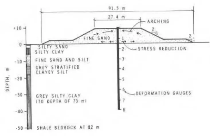
The pipe pile is 49 m long, and has an outside diameter of 324 mrn and a wall thickness of 6.35 mm. It was driven open ended in four sections
through a 9 m high, 27.4 m wide fine sand em- bankment with berms into a deep deposit of highly compressible layered silty clay (Fig. 2). The pile was instrumented with eight deformation
-50
1111
I S H h L f R E D R O C X & l 82 mFig. 2 Installation of steel-pipe pile, 49 m long, 32 cm diameter, through sand embankment gauges in order to measure the axial compres- sions caused by downdrag loads with time, and the soils below the fill were instrumented with settlement gauges and piezometers (Bozozuk and Jarrett, 1968)
.
SOIL
~ h & subsoils are of marine origin (Karrow, 1961). The soil profile (Fig. 2) consists of layers of silty clay, fine sand and silt, and stratified clayey silt, to a depth of 18 m. These layers rest upon a very thick deposit of grey silty clay, which extends to a depth of 73 m. In the upper 18 m, the cohesive soils are over-consoli- dated by about 30 kPa and have a shear strength of between 14 and 57 kPa as measured by a field vane. The liquid limits are equal to or less than the in situ water contents which vary from 28 to 60%. The silty clay formation below 18 m is over-consolidated by 80 kPa, and has a shear strength varying from 57 to 86 kPa and water contents varying from 35 to 60%. The ground- water table is normally less than 1.5 m below the ground surface. The engineering properties of these soils have been described in detail
(Bozozuk and Labrecque, 1968; Samson and Garneau, 1973).
EMBANKMENT
Construction of the sand embankment began in October 1964. It was raised to a surcharge heiqht of 10.7 to 11.3 m in November 1965, and finally paved in June 1967 (Samson, 1968; Samson and Garneau, 1973). When the test pile was installed in May 1966, the embankment had settled about 1.8 m. The fill settled an additional 761 mm by the end of May 1976, and continued to settle at a rate of 36.7 mm/a or 0.101 mm/d. Most of the settlement was due to consolidation of the upper 18 m of soil because the excess pore water pres- sures had essentially dissipated to this depth. At 27.5 m, however, the excess pore water pressure was still 75% of the applied vertical stress.
TEST PILE
The test pile settled 694 mm during this time; the rate of settlement at the end of May 1976 was 35.5 mm/a or 0.097 m / d . Downdrag loads generated in the pile reached a peak 1.27 MN five years after installation (Bozozuk, 1972) and
1.52 MN at the end of May 1976 (Fig. 3 ) : They occurred at the neutral point, which coincided
with the base of the fine sand and silt formation The distribution of skin friction load is related directly to tpe horizontal effective stress acting on the pile. The magnitude and distribu- tion of these stresses could be reasonably
estimated at the centre line of the embankment at the end of construction, but after several years the large differential settlements developed arching stressez at the top and stress reductions at the base of the highway fill (Fig. 2). The changed stress conditions affected the dis- tribution of downdrag load in the pile within the sand embankment (Bozozuk, 1972).
The horizontal effective stress on the pile below a depth of 27.5 m (36 m from top of pile, Fig. 3) is also difficult to determine. In addition to the known high excess pore water pressures generated from the weight of the embankment, un- known excess pore pressures are generated as the pile is pushed continuously (at a rate of 0.097 mm/d) into the very thick silty clay formation. Consequently, little or no positive skin friction was mobilized on the pile shaft below this depth. Since the horizontal effective stresses are therefore generally unknown 10 years after installation and cannot be determined, the behaviour of the pile in terms of effective stress and the coefficient of friction between the pile and soil could not be analyzed.
LOAD TEST PREPARATION AND PROGRAM
The magnitude and distribution of downdrag load in the pile determined from measured compressions 10 years after installation is shown in Fig. 3. For the maximum load PN = 1.52 MN, the unit stress in the steel pile exceeded 190 M N / ~ ~ , which was close to the maximum allowable for the steel. Consequently the pile had to be strengthened if any load tests were to be carried out.
The open-ended hollow-pipe pile was pumped free of water on 25 August 1976 and filled with con- crete having a 28-day strength of 41.4 MN/~*.
The top of the pile was fitted with an enlarged cap to provide adequate support for a 500 t loat cell, required to measure the applied test loads. In addition, the exposed shaft was instrumented with four SR-4 strain gauges in order to measure the composite deformation modulus D from the proposed load tests. The modulus was required to determine the distribution of applied loads in the pile from the compressions measured with deformation gauges.
A steel loading frame, capable of supporting 400 t of concrete blocks was erected over the pile. Each of the two frame supports consisted of three 1 m diameter vertical steel pipes resting on a 2.1 m wide, 6.1 m long foundation pad, placed directly on the paved roadway on both
sides of the pile. The centre of o
1
each pad was located 3.05 m or 9.5 Z U
pile diameters from the test pile.
z s
This distance was considered neces- 2,
sary to reduce or eliminate any 2 -
S O I L
transfer of stress from the founda- P R O F I L E 0 0 . 5 1 1 . 0 2 1 . 5 2 2 . 0 3 2 . 8 2
2:
tion pads to the test pile. A 500 t capacity hydraulic jack, powered with nitrogen gas was positioned over the load cell on the test pile. The test program was divided into
three phases : - 1 0 E
Schedule A: Investigation of the Y
performance of the pre-
-
15 istressed friction pile 0
loaded to PN/3, 2 PN/3 Y
and PN (PN = 1.52 MN),
-
20over a period of 11 L
STRATIFIED
days. CLAYEY SILT 4 '
2
Schedule B: Investigation of the
r:;
performance of the pile loaded to 2 PN/3, 4 PN/3 and 2 PN, over a period of 7 days. SILTY CLAYSchedule C: If the pile did not
1:
fail during loading in Schedule B
-
1) Load pile to fail- ure ;
2) Subject pile to a series of cyclic
loads to investi- S O
gate the effect 0 0 . 5 0 1 . 0 0 1 . 5 0 2 . 0 0 2 . 5 0 3 . 0 0 on shaft friction. A X I A L P I L E L O A D . M N
These tests were to be completed in Fig. 3 Load distribution in test pile two days.
Loading began 28 October 1976, 64 days after the TEST RESULTS concrete was placed in the pile. The deformation
modulus of the concrete-filled pipe pile was The loading procedure consisted of applying an obtained from the load tests and is reported initial load of 0.20 MN (first load that could along with other relevant data in Table I. be read on the load cell), followed by incre-
TABLE I
Engineering Data for Concrete-Filled Steel-Pipe Pile
Distance from Perimeter in Cross-Section Area, m 2 Deformation
top of pile, contact with modulus, D**
m soil, m Steel, As* Concrete, Ac Total, A m / n 2 0
-
12.2 1.42 8.15 x 75.67 x 83.82 x 41 200t 12.2-
24.4 1.32 7.73 x 75.67 x 83.40 x 40 400 24.4-
36.6 1.22 7.30 x 75.67 x 82.97 x 39 500 36.6-
48.8 1.12 6.88 x 10'~ 75.67 x 82.55 x 38 700*
Steel area adjusted for deformation gauge casings which are welded continuously to outside of pipe pile.1
**
Deformation modulus D = [Ac Ec+
As Es]Es = 200 000 14Pl/rn2; Ec = 24 100 blhl/m2 t Measured with strain gauges.
/
-
-
N O T E : 1 . 5 2 M N L O A D M A l N T A l N C D-
F O R S I X D A Y S 1 1 1 1 1 1 b-
F O O T O F D E F O R M A T I O N G A U G E-
- 2 5s
0 a 30 u u 35 V)-
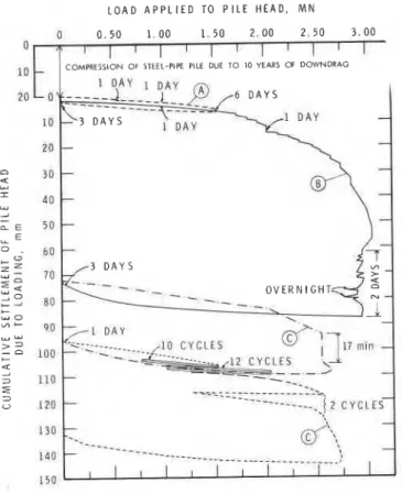
4 0 a 4 5ments of 0.10 MN every 10 min until the required load was reached. At each load, the settlement of the pile head was measured with two dial gauges reacting against two steel reference beams supported on steel posts driven into the fill beyond the influence of the loading frame. An independent measure of the settlement was obtained with engineering level surveys re- ferenced to a deep bench mark. Pile compres- sions registered by the deformation gauges were recorded manually and automatically with an electric recording system. A similar procedure was followed during unloading of the pile. The loading record for the complete study is shown in Fig. 4.
Schedule A
The first load equal to PN/3 = 0.51 MN was
applied in 30 min and maintained for 17 h. Apart from the initial elastic compression of 1.2 mm
(Fig. 5), no additional settlement occurred over this period of time. The distribution curve for the applied load (Fig. 3) shows that it was carried by the prestress in the pile.
The second load equal to 2 PN/3 = 1.02 MN was maintained for 19 h. The initial settlement of
2.7 mm (Fig. 5) also did not change over this time period, but this may have been due to a small reduction in applied load after 19 h (Fig. 4). The load distribution curve (Fig. 3) shows that this load was also carried by the prestress in the pile.
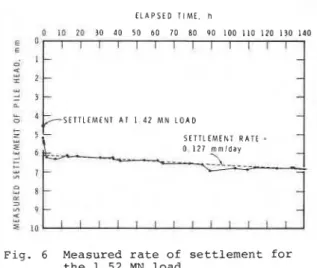
The third load equal to PN = 1.52 MN was also essentially carried by the prestress in the pile, but the slope in the upper portion of the curve indicates that some of the load may have been carried by positive skin friction (Fig. 3). A very small portion of the load was also trans- ferred to the pile below the neutral point. The load was maintained for about six days
(Fig. 6). After the initial settlement of 5.2 mm (Fig. 5), the pile continued to settle at an average rate of 0.127 mm/d (with respect to fill) or 3.8 mm/month. Before it was loaded, however, it was settling 0.12 mm/month slower than the fill, indicating that if this load was applied for a long period of time, positive skin friction could evenutally be mobilized along the whole length of the pile. This is a real possibility because the pile can move very slowly into the soil. This could not happen if the pile was bearing on rock.
ELAPSED T I M E . d a y s
Fig. 4 Loading record for test pile
L O A D A P P L I E D TO P I L E H E A D . MN 0 0 . 5 0 1.00 1.50 2.00 2.50 3.00
0 I I I I I I l ] I I I I
~n
L I
COMPRESSION O F STEEL-PIPE PILE DUE T O lo YEARS O F D O W N D R A G 10 l 3 D A Y S D A Y 20t
-
/ 3 D A Y S-
-
-
-
-
- -
17 min 7Fig. 5 Load:deformation behaviour of test pile The pile was unloaded in 12 increments and allowed to rest for three days (Fig. 4). It re- bounded 5.4 mm during this time, indicating a net settlement of 1.3 nun due to the loading program.
Schedule B
The first load equal to 2 P N / ~ = 1.02 MN caused an initial settlement of 4.1 mm (Fig. 5)
.
After 17 h, the load dropped off to 0.97 MN (Fig. 4) and the settlement reduced to 3.9 mm, again showing that the preloaded pile can support this load.For the second load, 4PN/3 = 2.03 MN, the initial settlement of 12.3 mm (Fig. 5) increased by
2.4 mm to 14.7 mrn after 22 h. Figure 3 shows
that a large portion of the load was carried by positive skin friction mobilized within the sand embankment. Some of the applied load was also transmitted to the pile below the neutral point. The third load, 2 PN = 306 MN, was reached momen- tarily at a large settlement of 53 mm (Fig. 5 ) .
As this load could not be maintained, it defined
the peak load at plunging failure. The load was readjusted to between 2.9 and 2.95 MN, but even this load reduced to about 2.8 MN overnight on two occasions. Attempts to maintain the 2.95 MN
load resulted in an increase in settlement of
34 nun in 52 h.
Figure 3 shows the load distribution in the pile after the applied load was allowed to decrease from 3.06 MN to 2.82 MN. Positive skin friction was now mobilized down to the neutral point, and
ELAPSED TIME, h I I I I I I I I I I I I I
-
-
-
-
--
? S E T T L E M E N T A T I 4 2 M N L O A D-
--
SETTLEMENT RATE 0 1 2 7 r n r n i d a yFig. 6 Measured rate of settlement for the 1.52 MN load
although some load was transmitted to the pile below, very little additional positive skin friction and no additional end bearing were mo- bilized. As the pile had moved down about 80 m , it follows that the maximum skin friction and end bearing were fully mobilized for the effective stress conditions that existed in the soil at the time. The pile was unloaded gradually in about 20 increments and allowed to rest for three days. It rebounded 15.3 mm, leaving a net total settle- ment of 72.3 mm.
SCHEDULE C
The pile was loaded rapidly in increments of 0.5 MN to a plunging failure load of about 2.55 MN (Fig. 5 ) . This was only 83% of the peak load observed in Schedule B, indicating that the large pile movements had reduced the amount of positive skin friction that could be mobilized. Three series of cyclic loads were applied to the pile after it was unloaded and allowed to rest for one day (Fig. 5). Cycling the load 10 times between 0.76 and 1.52 MN caused a residual settlement of 0.00 m/cycle. Cycling the load 12 times between 1.02 and 2.03 MN also caused a residual settlement of 0 . 0 8 mm/cycle. The net settlement at a load of 2.03 MN after 22 load
cycles was 13.8 mm, which surprisingly compared with the settlement measured on the pile for the same load in Schedule B (Fig. 5 ) .
Two cycles of load between 1.27 and 2.55 MN caused very large pile movements. The loads were then increased in increments of 0.05 MN to a maximum of 2.72 MN, for a total settlement of 143 mm.
It appears that cycling the load about 10 times within a stress range of 2 3 3 1/3% of PN has very
little destructive effect on the load carrying capability of the preloaded friction pile. Cycling t h e load did however cause a residual settlement of 0 . 0 8 nun/cycle.
DISCUSSION
The axial compression on the pile due to the development of downdrag load over a period of 10 years is shown at the top of Fig. 5. This compression represented a locked-in load of 1.52 MN, which was fixed in the steel pipe when it was filled with concrete. If the locked-in stresses or preload had been ignored, the load distribution curves (Fig. 3) would have been completely different.
Fellenius (1972) demonstrated that downdrag loads on a pile add on to existing static dead loads as consolidation of the surrounding soil takes place and if the dead load is increased the downdrag loads redevelop and add on to this new level of load. This implies that all piles must be designed to carry the design dead loads and the maximum downdrag load that can develop during the
life of the structure. The test program described in the paper, however, shows that the downdrag load or locked-in preload could be available to carry short-term transient or live loads. This is very important because the trend of present- day construction is toward a decrease in the weight of the structures and a relative increase in transient loads which can amount to 60% of the total loads acting on the foundations (Bakholdin and Sturov, 1979).
The testing program demonstrated that axial loads up to the locked-in downdrag load can be applied to the friction pile for about one month if 4 mm of settlement is acceptable. Larger loads can also be carried but for considerably smaller periods of time. Positive skin friction was mobilized for the full length of the pile when the larger loads were applied. Plunging failure occurred however when the load was increased to two times the maximum downdrag load.
The pile "set up" very quickly after it was loaded to plunging failure. Following a rest period of three days, plunging failure occurred at 83% of the initial peak failure load or at 90% of the residual bearing capacity (defined at settlements exceeding 60 mm). After a further rest period of one day it was possible to apply 22 cycles of load up to a stress level of 2.03 MN (4PN/3). Applyinq a total of 24 load cycles did not further reduce the bearing capacity of the pile.
CONCLUSIONS
1. The 1.52 MN downdrag load, which developed in the floating friction pile over a period of 10 years, can be considered as a prestress that is capable of responding to transient, cyclic and short-term live loads.
2. Applied axial loads equal to or less than PN (1.52 MN) can be supported for one month if 4 mm of settlement is acceptable.
3. Applying cyclic loads within a stress level of PN '33 1/3% does not significantly affect the shaft friction mobilized on the pile. Each cycle causes a residual settlement of
.08 mm/cycle.
4. Pile "set-up" is very rapid in the marine clays at the test site.
5. To support applied loads varying from PN to 2 PN, positive skin friction must be mobilized in the upper consolidating soil.
Thanks are due to F. Bgrard, Director of Engi- neering, Quebec Autoroute Authority, who allowed the load tests to be carried out, and to
B.H. Fellenius, formerly of Terratech Ltd., who helped plan and carry out the test program. The assistance of the technical staff of the Geo- technical Section of the Division of Building Research, who often had to work long hours under adverse conditions, is gratefully acknowledged. This paper is a contribution from the Division of Building Research, National Research Council of Canada, and is published with the approval of the Director of the Division.
Bozozuk, M. (1972). Downdrag measurements on 160-ft floating pipe test pile in marine clay. Can.Ge0tech.J. (9), 2, 127-136. Bozozuk, M., and Jarrett, P.M. (1966). Instru-
mentation for negative skin friction studies on long piles in marine clay on tht Autoroute du Qugbec. Presented at the Workshop Meeting of the International Bridge, Tunnel and Turnpike Association, Montreal. (Reprinted as NRCC 10046)
Bozozuk, M., and Labrecque, A. (1968). Downdrag measurements on 270-ft composite piles. ASTM-STP No. 444, 15-40.
Fellenius, B.H. (1972). Down-drag on piles in clay due to negative skin friction. Can. Geotech. J. (9), 4, 323-337.
Karrow, P.F. (1961). The Champlain Sea and its sediments.
2
Soils in Canada, pp. 97-108. University of Toronto Press, Toronto. Samson, L., (1968). Discussion of "Settlementobservations at Kars Bridge by W.J. Eden and H.B. Poorooshasb (vol. V, no.1: 28-45)
."
Can.Ge0tech.J. (51, 4, 245-248.Samson, L., and Garneau, R. (1973). Settlement performance of two embankments on deep compressible soils. Can.Ge0tech.J. (lo), 2, 211-226.
REFERENCES
Bakholdin, V.V., and Sturov, V.I. (1979). Considerations of transient loads when designing pile foundations. (Soil Mechanics and Foundation Engineering) Scientific- Research Institute of Bases and Under- ground Structures, Plenum Publishing Corp., New York. Translated from Osnovanii, Fundamenty i Mekhanika Gruntov, No. 5, 14-15.
Soil
mechanicsand foundation engineering
-Proceed-
ings o f the 10th international conference, Stockholm,
15-19 June 1981
1981,28 cm, c.3500pp.,
4
vols., Hfl.8501
$380 12170 Over 500 papers(40
in French, rest Enghsh) from con- tributors throughout the world. Prediction and perfor- mance; tunnelling in soils; groundwater and seepage problems; laboratory testing; soil/structure interaction; environmental control (incl. waste material); soil exploration and sampling; pile foundations; saving cities and old buildings; soil dynamics; slope stability; soil improvement.All
papers were selected and reviewed by the national societies of the International Society for Soil Mechanics and Foundation Engineering.CONTENTS
1. Prediction and performance (Accuracy of predictions and its determination; Application of probability and decision theory design; Factors governing the performance of buildings and other structures). Pile foundation problems in white chalk; Settlements under intermittent loading; Settlement calculation by a new strength theory; Construction of a pile wall in a rock- fill dam; Rheological definition of loess subsidence; Insulation for foundations and buried services; Land reclamation using fine-grained dredged material; Settlement analysis of tanks on soft clay; Pitfalls of back-analyses; Observations of creep during heave; Consolidation of sensitive clays; etc.
2 Tunnelling in soils (Case records of tunnel constructions; Effects of different excavation/construction techniques; New calculation methods; Mapping and control systems). Strain field around a tunnel in stiff soil; Principles of tunnel design for seismic regions; Analytical study of NATM; etc.
3. Groundwater and seepage problems (Prediction and measure- ment of groundwater conditions and flow; Internal erosion and piping, hydraulic fracturing, etc.; Control of ground water; Effects of changes in groundwater level). Theory of non-linear seepage; Experience in plastic filter application; Jet grout method and cut-off walls stability; Soil drainage and stability of slopes; Initial gradient in a dense glacial till; Structural improvement of alluvial soils; Seepage interaction ctc. 4. Laboratory testing (Relevance of laboratory soil testing methods; Standardization of laboratory tests for practical application; New laboratory testing methods; Model tests). Investigation of soils creep; Mechanical properties of soft rock and rock mass; Laboratory and pressuremeter tests on a stiff clay; Laboratory testing of vertical drains; The consolidation properties of a soft rock; Dynamic compaction of rockfill samples; Model for determining of soil parameters; etc. 5. Soil structure interaction (Case histories and observation of real behaviour; Design and construction procedures which take account of soil/structure interaction; Acceptable deformation in relation to the performance and function of structures). An elastoplastic analysis of anchored walls; Computing foundation slabs with building rigidity; Soil interaction in buried structures; A method of settlement calculation; On the validity of Wink- ler's principle; Design and monitoring of an embankment on alluvium; Anchor slab structure retains earth fill; etc.
6. Environmental control (Waste material in earth structures and protection against groundwater pollution; Erosion protec- tion; Change of geotechnical properties due to pollution; Sub- sidence due to lowering of the groundwater level and to the withdrawal of oil and mining). Fly ash as fill material; Mecha- nical behaviour of coal fly ashes; Mechanisms for detoxifying soil; Pollution in peats; Environment protection in Italy; etc.
7. Soil exploration and sampling (In-situ testing and deforma- tion measurements; Quality (scatter) of soil data in relation to specific foundation problems; New techniques for soil sampling and penetration tests). Portable geotechnical field equipment; The static-dynamic penetrometer; Geological interpretation of SIR data; Energy diisipation on the SPT;O~S; ~ i e l d investiga- tions of clay soils; A sampler-with a new type of shutter; Tests in alluvial sand with the PQS probe; etc.
A. A.
Ralkema Publishers. P.O.
Box
8. Pile foundations (Use of stress-wave theory in prediction of pile performance; Control methods for driven and cast-in-place piles; New pile systems and new pile driving methods; Friction piles; Behaviour of pile groups; Failure of pile foundations). Pile foundation settlements; Load test on friction piles in clay; Bearing capacity of pile preloaded by downdrag; Consolidation due to lateral loading of a pile; Downdrag on bitumen coated piles in a warm climate; Skin friction on underslurry piles; H
steel piles in dense sand; Load tests on large bored piles in sand; Installation of piles for marine structures in the Red Sea;
9. Saving cities and old buildings (Geotechnical problems con- nected with the protection of existing structures against sub- sidende and floods; Investigation of the integrity, durability and bearing capacity of structures; Underpinning and other methods of saving structures and ground). Foundation docu- mentation for conservation planning; Preservation of old build- ings in the USSR; The Tower of Pisa: recent observations; etc. 10. Sod dynamics (Design of machine foundations; Damage by vibrations and protection of buildings and structures; Effect of dynamic loads on strength and deformation properties of soils). Prediction of seismic pore-water pressures; Characteris- tics of embankment dams during earthquakes and man-in- duced vibrations; Displacements of cyclically loaded structures embedded in sands; Saturated sands under cyclic loading; etc. 11. Slope stabiity (Detection and classification of potential landslide areas; Factors influencing the short- and long-term stability of slopes; Analysis of slope stability, including dams; Slide warning systems and methods of prevention of land- slides). Stability of natural slopes in quick clay; Dynamic pro- gramming in dam slope design; Relationship between limit equilibrium slope stability methods; etc.
12. Soil improvement (Compaction; Reinforcement of soil; Grouting, excluding control of groundwater flow and seepage; Consolidation by preloading and/or vertical drains, electro- osmosis, etc.; ~oifstabilizacon by ion exchange; Thermal stabi- lization). Geodrain installation at Lornex Tailings Dam, Cana- da; ~ o i i n a i l i n ~ : a technique of in-situ reinforced earth;-soil improvement by lime-fly ash slurry injection; etc.
Discussions and additional papers (In vol. 4, end 198 1).
Soft ground tunneling
-Failures and displacements
1980,25 cm, c.200 pp.,
Hfl.45
/
$22.00/
£9.00 Based on a specialty session on soft ground tunneling held during the 6th Panamerican conference on soil mechanics and foundation engineering, held in Lima, Peru in December 1979. Geotechnical problems; weathered-rock portion of the Wilson tunnel, Honolulu; failure of shafts & tunnels in soft soils; lost ground sub- sidences in 2 shallow tunnels; assessment of tunnel sta- bility in clay by model tests; settlements upon soft- ground tunnelling; tunnels under compressed air; pre- diction of surface movements; stress path approach for a tunnel driven in stiff clay; etc. Editors: Director & scientist at Inst. Ingenieria, Univ. Mexico.Weak
rock
-Proceedings of the international sym-
posium, Tokyo, 21
-24 September 1981
1981,25 cm c.1500 pp., Hfl.396 /$195.00 IE79.50 Knowledge on weak rock has become increasingly important for the design and construction of dams, underground openings, undersea tunnels, mines, foun- dations of nuclear power stations, large suspension bridges and transmission towers, long slopes, etc. The papers and discussions are by engineers interested in engineering properties, in situ investigations, special- ized theories, analyses, adequate designs, construction practices, dynamics and tectonics. The symposium was sponsored by ISRM, ISSMFE, etc.
This publication is being distributed by the Division of Building R e s e a r c h of the National R e s e a r c h Council of Canada. I t should not be reproduced in whole o r in p a r t without p e r m i s s i o n of the original publisher. The Di- vision would b e glad to b e of a s s i s t a n c e i n obtaining s u c h permission.
Publications of the Division m a y be obtained by m a i l - ing the a p p r o p r i a t e r e m i t t a n c e ( a Bank, Express, o r P o s t Office Money Order, o r a cheque, m a d e payable t o t h e R e c e i v e r G e n e r a l of Canada, c r e d i t NRC) t o the National R e s e a r c h Council of Canada, Ottawa. KIA OR6. Stamps a r e not acceptable.
A lis t of a l l publications of the Division is available and m a y b e obtained f r o m the Publications Section, Division of Building R e s e a r c h , National R e s e a r c h Council of Canada, Ottawa. KIA OR 6.