HAL Id: hal-01022153
https://hal-enac.archives-ouvertes.fr/hal-01022153
Submitted on 30 Sep 2014
HAL is a multi-disciplinary open access
archive for the deposit and dissemination of
sci-entific research documents, whether they are
pub-lished or not. The documents may come from
teaching and research institutions in France or
L’archive ouverte pluridisciplinaire HAL, est
destinée au dépôt et à la diffusion de documents
scientifiques de niveau recherche, publiés ou non,
émanant des établissements d’enseignement et de
recherche français ou étrangers, des laboratoires
An improved method to decode GPS L2C/L5 navigation
message : combination of the inner and the outer
channel codes
Axel Javier Garcia Peña, Marie-Laure Boucheret, Christophe Macabiau,
Anne-Christine Escher, Lionel Ries, Jean-Louis Damidaux, Stéphane Corazza
To cite this version:
Axel Javier Garcia Peña, Marie-Laure Boucheret, Christophe Macabiau, Anne-Christine Escher, Lionel
Ries, et al.. An improved method to decode GPS L2C/L5 navigation message : combination of the
inner and the outer channel codes. ION ITM 2009, International Technical Meeting of The Institute
of Navigation, Jan 2009, Anaheim, United States. pp 836-850. �hal-01022153�
An improved method to decode GPS L2C/L5
navigation message: combination of the inner
and the outer channel codes
Axel Garcia Pena, Centre National d’Etudes Spatiales (CNES)/TeSA Marie-Laure Boucheret, IRIT, Université de Toulouse/ENSEEIHT Christophe Macabiau, Ecole Nationale de l’Aviation Civile (ENAC) Anne-Christine Escher, Ecole Nationale de l’Aviation Civile (ENAC)
Lionel Ries, Centre National d’Etudes Spatiales (CNES) Jean-Louis Damidaux, Thales Alenia Space (TAS)
Stephane Corazza, Thales Alenia Space (TAS)
BIOGRAPHY
Axel Garcia is a telecommunication engineer. He followed a European program of double degree: he graduated in 2006 from SUPAERO (Ecole Nationale Superieure de l'Aeronautique et de l'Espace) in Toulouse, France and he also obtained the engineer degree from ETSETB-UPC (Escola Tecnica Superior d’Enginyeria de
Telecomunicacions de Barcelona – Universitat
Politecnica de Catalunya, Spain) in 2006. He is now a
PhD Student at ENAC and studies improved
methods/algorithms to better demodulate the GPS signals as well as future navigation message structures.
Marie-Laure Boucheret graduated from the ENST Bretagne in 1985 (Engineering degree in Electrical Engineering) and from Telecom Paris in 1997 (PhD degree). She worked as an engineer in Alcatel Space from 1986 to 1991 then moved to ENST as an Associated Professor then a Professor. Currently, she is a Professor at
ENSEEIHT. Her fields of interest are
digital communications (modulation/coding, digital
receivers, multicarrier communications…), satellite
onboard processing (filter banks, DBFN…) and navigation system.
Anne-Christine Escher graduated as an electronics engineer in 1999 from the ENAC in Toulouse, France. Since 2002, she has been working as an associate researcher in the signal processing lab of the ENAC. She received her Ph.D. in 2003.
Christophe Macabiau graduated as an electronics engineer in 1992 from the ENAC in Toulouse, France. Since 1994, he has been working on the application of satellite navigation techniques to civil aviation. He received his
PhD in 1997 and has been in charge of the signal processing lab of the ENAC since 2000.
Lionel Ries is a navigation engineer in the "Transmission Techniques and Signal Processing Department", at CNES since 2000. He coordinates GNSS technical activities, including GNSS signals performances evaluation and receiver algorithms development (BOC and MBOC, GIOVE, GPS L2C & L5, etc.). He graduated from the Ecole Polytechnique de Bruxelles, at Brussels Free University (Belgium) and then specialized in space telecommunications systems at Supaero (ENSAE), in Toulouse (France).
Jean-Louis Damidaux is the current Head of Navigation System Architect Group in the Business Unit Navigation and Integrated Communication at Thales Alenia Space (TAS-France). He is involved in the navigation domain since 1996 and graduated from ESE in 1977.
Stéphane Corazza has performed hardware and software developement for GALILEO/GPS/EGNOS receiver, and GNSS system engineering for Thales Alenia Space company. He has received an Electronics Engineering degree from the National Institute of Applied Sciences (INSA - Lyon, France, 1994).
ABSTRACT
The current GPS provides an open positioning service by broadcasting the L1 C/A signal. This signal allows precise positioning in environments with a high C/N0, i.e. where the direct GPS signal is received without any significant attenuation, with no obstacle on the line of sight between the GPS satellite and the user receiver, and without multipath. However, without assistance, in indoor and in
narrow urban environments the previous statements are
no longer valid and the C/N0 is not always high enough to
allow a correct data message demodulation/decoding or a satisfactory tracking process.
The introduction of two new signals, GPS L2C and GPS L5, has improved this capacity of retrieving the correct message; the information without errors. These new signals are constructed with a serial implementation of channel codes: first, a convolutional code (171,133) used to implement the FEC (Forward Error Correction) and, second, a new and more performing code, the CRC-24Q, aimed at detecting words with uncorrected errors. In a serial implementation we call the first code the inner code, in this case the convolutional code, and the second code the outer code, in this case the CRC-24Q. However, although these signals fairly improve the decoding performance compared to GPS L1 C/A signal, they still do not provide an ideal service: for any C/N0, the BER can be improved.
Therefore, the aim of the method presented in this paper
is to reduce the C/N0 required by a GPS L2C/L5 receiver
to obtain a determined BER value during the decoding process compared to the C/N0 levels of the traditional
decoding techniques. This method reuses the imposed data message structure in a different form exploiting one of the only available degrees of freedom provided by this defined system: the data processing. More specifically, the proposed method combines the two message channel codes (inner and outer) in order to develop a new decoding process performing better than the conceived serial implementation of the two individual decoding processes.
The main idea of the method is to search through a modified Viterbi Algorithm for the most probable sequence being emitted that verifies the CRC-24Q. Indeed, this latter code determines if the sequence belongs to the coded words alphabet.
I. INTRODUCTION
The current signal GPS L1 C/A was not originally conceived for being used in indoor or in narrow urban
environments where the value of C/N0 is not high enough
to allow a satisfactory data message demodulation/ decoding process in terms of Bit Error Rate (BER). The decoding is the process of translating received messages into codewords of a given code. This translation is accomplished by estimating the plus probable emitted codeword for each received message. The demodulation process is the act of extracting the original information-bearing signal from a modulated carrier wave. Therefore, the demodulation process is accomplished after applying the decoding, once the codewords are transformed into
information words. The decoding is a part of the demodulation.
This demodulating/decoding performance of the GPS L1 C/A signal is satisfactory enough for the original applications for which the signal was aimed at. However, the users’ needs have evolved and nowadays applications such as the urban positioning are really important and should be available in any kind of environments. For example, a car searches the fastest path to go from one place to another in a city as Paris which has narrow streets surrounded by high buildings.
The introduction of two new signals, GPS L2C and GPS
L5, has improved this demodulating/decoding
performance: lower levels of C/N0 are required to obtain
the same BER values. These signals have as a major
evolution, in terms of demodulation/decoding
performance, the introduction of a convolutional code (171,133) which allows the implementation of the Forward Error Correction (FEC). Moreover, the data of the GPS L5C and GPS L2C mode CNAV signals also incorporate a new code aiming at detecting the remaining errors not corrected by the convolutional code. This new code is the CRC-24Q and is called in the telecommunications field the outer code whereas the convolutional code is known as the inner code.
However, even with the evolutions introduced with these new signals, the BER can still be improved for the new applications in urban and/or in indoor environments. Therefore, before new signals are proposed for the future GNSS systems (GPS III, GALILEO, etc), new methods and algorithms can be developed in order to improve the BER in low C/N0 environments.
The method presented in this paper changes the traditional use of the two channel codes implemented on the signals GPS L2C and GPS L5. Instead of using the inner channel code in order to execute the FEC and the outer channel code to detect the errors, the proposed method combines them in order to achieve a FEC with a bigger correction capacity. In other words, the new use of both channel codes results in a process capable of correcting much more errors than the traditional one. It is however to be noted that a minor drawback encountered on the GPS L2C mode NAV data message increases the wrong decoded words that are not detected. However, the gain in terms of number of good decoded words is far more interesting than the impossibility of detecting wrong words
Other advantages of the proposed method are the lack of any external contribution or aid such as additional information (A-GPS) or complementary signals (EGNOS) to work, the absence of impact on the satellite payload and the easy implementation in all the GPS receivers.
Finally, apart from the main algorithm, some variations are presented in order to enhance the time of execution and the decoding performance of the new method. These variations are the use of a priori probabilities of the bits of the navigation data message, the implementation of a sliding window, the discarding of some possible received sequences, the imposition of the initial state and the variation of the number of searched candidates.
The organization of the paper is the following: a brief description of the signal structures, followed by a presentation of the traditional use of the channel codes. Afterwards, the main algorithm is presented and some possible variations are also introduced. Finally, the simulations and the conclusions are discussed.
II. NAVIGATION MESSAGE DESCRIPTION
A brief description of the signals GPS L2C and GPS L5 is given in order to provide a better understanding of the application of the channel codes. A full description can be found in [4].
First, the general description of the data transmitted on the channel is given, and, second the inner and outer channel codes together with the data message content are introduced.
A. Encoding of the data transmitted to the channel:
This subsection presents the encoding of the data transmitted on the channel or, in other words, the application of the inner and the outer code over the data message content.
The channel codes are applied in a serial implementation as shown on figure 1: the data information is the input of the outer code, the output of the outer code is the input of the inner code, and the output of the inner code is transmitted to the channel.
Figure 1: Encoding of the data to be transmitted to the channel: serial implementation of the inner and outer channel codes.
B. GPS L2C mode NAV data message structure – Outer Code
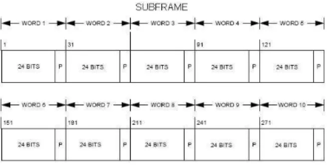
The content and structure of the GPS L2C navigation message is exactly the same as the GPS L1 C/A. Therefore, the structure of the superframe, frame, subframe and word remains invariant. Figure 2 shows the subframe structure:
Figure 2: Subframe of the GPS L2C mode NAV data navigation message
Each frame is made by 5 subframes, each subframe contains 10 words and each word is composed of 32 coded bits but only the last 30 are transmitted with the current word. The first 2 bits are also transmitted but with the previous word. Among these 32 bits, the last 6 ones are the parity bits created by the extended Hamming code (32,26), the outer code. Therefore, with the GPS L2C mode NAV signal data, the verification of the outer code is applied for each word; in other words, the information is validated or discarded by words.
C. GPS L5 Data message structure and GPS L2C mode CNAV data message structure – Outer Code:
The contents and structures of the navigation message data of GPS L5 and GPS L2C mode CNAV signals are the same and they are completely different from these of GPS L1 C/A. The subframe includes 276 information bits plus CRC of 24 bits encoded by a cyclic code (CRC-24Q), the outer code. Figure 3 illustrates the subframe structure:
Figure 3: Subframe of the GPS L2C mode CNAV data and GPS L5 navigation message
In this case, the verification of the outer code is performed over the subframe; therefore the information is validated or discarded by subframes.
D. Inner Code – Convolutional Code:
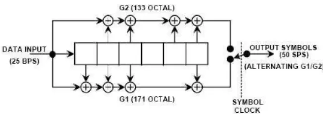
The inner code implemented by the two navigation messages is the same convolutional code (171,133). Figure 4 shows the encoding block scheme of this code [4]:
Figure 4: Encoding of the GPS L2C/L5 convolutional code (171,133)
III. TRADITIONAL USE OF THE INNER AND OUTER CHANNEL CODES
In this section, the traditional techniques implemented to decode the channel codes of the GPS L2C and GPS L5 navigation messages and the traditional demodulation strategy of the GPS receivers are presented.
A. Demodulation Strategy of the GPS receivers:
The traditional demodulation strategy of the GPS receivers can be divided into 3 mains steps:
1. Applying the inner code in order to correct the errors
introduced by the transmission of the message: process known as Forward Error Correction (FEC).
2. Applying the verification of the outer code in order
to detect which words/subframes have been wrongly decoded.
3. The words/subframes failing the verification are
discarded whereas the other ones are considered free of errors.
Figure 5 summarizes the demodulation strategy:
Figure 5: Traditional Demodulation Strategy of the GPS Receivers
B. Inner Channel Code:
The inner code is a convolutional code, therefore the two principal decoding methods are the Viterbi [1],[2], and the BCJR (Bahl, Cocke, Jelinek and Raviv) [3] algorithms. The Viterbi technique minimizes the probability of error of a determined received sequence (several symbols) or, in other words, searches the most probable transmitted sequence, whereas the BCJR method minimizes the probability of error of each received symbol or, in other words, searches the most probable transmitted symbol. Nevertheless, the most used decoding method is the
Viterbi algorithm because, although the performance of
both methods is almost the same, the Viterbi algorithm has smaller computational and storing costs.
The principle of the Viterbi algorithm is first to calculate a distance for each possible emitted sequence. This distance is called accumulated distance and only depends on the travelled path. Second and last, the algorithm chooses the sequence with the minimum accumulated
distance as the emitted sequence, because the bigger the
accumulated distance is, the less probable the sequence is. The accumulated distance of a sequence is the sum of the
transition distance of each information symbol of the sequence. A transition distance is the hamming distance or the vectorial distance between the receiver estimated information symbol and the information symbol within the sequence. In other words, it is the distance between the receivers estimated values of the code symbols (representing an information symbol) and the code symbols (representing an information symbol) within the sequence:
Transition Distance kth info symbol =
∑
=
−
N i ki kic
r
1 2 where:- N: Number of code symbols encoding a information
symbol
- rki: Estimated ith code symbol value of the kth
information symbol.
- cki: Theoretical ith code symbol value from the kth
information symbol within the inspected sequence Moreover, the Viterbi algorithm really does not calculate the accumulated distance for all the possible transmitted sequences but eliminates some sequences that at one step have a bigger final accumulated distance than some other sequence(s). This moment occurs when two different sequences (partially or totally different) begin to follow the same path, or in other words, are equal from this point The reason is simple: the accumulated distance depends on the followed path; therefore, until the moment where they begin to follow the same path, their accumulated
distance is different, but from the point where they are equal, the new distance to be added is the same for both sequences; meaning that only the previous accumulated
distance serves to differentiate the sequences. Therefore, the sequence with the biggest accumulated distance at the moment when they become equal will always have a bigger accumulated distance.
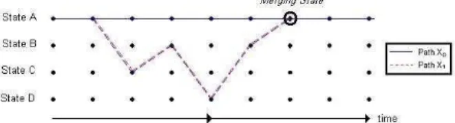
Finally, a convolutional code has memory. Therefore, the encoding of the present bits depends on a certain number of past bits. The values of these past bits define a State and thus the number of different States is equal to 2number_past_bits. Then, if the current coded bit depends on the past bits or on the State, it is obvious that two different sequences will continue to be equal from the moment that they arrive at the same State. Therefore, the moment previously defined as the one when a sequence can be eliminated is found when two or more sequences
reach the same State (figure 6). When two or more paths reach the same State, in this paper we will say that these paths merge.
Figure 6: Viterbi Trellis - Two sequences merging at a State
Additionally, note that even if two sequences reach the same State, one may think that these sequences could follow at some future point different paths and thus the sequence with the bigger accumulated distance should not be eliminated. However, there is no impediment to find another sequence with the previous smaller accumulated
distance following the same path as the sequence with the previous bigger accumulated distance. Therefore, due to the existence of this last sequence, the sequence with the bigger accumulated distance can be righteously eliminated.
Last, in this paper we will define the state difference as the difference between the accumulated distances of two sequences merging in a state.
C. Outer Channel Code:
The outer codes are the extended Hamming (32,26) and the CRC-24Q codes. Their principal function is to verify that the parity bits (6 for the extended Hamming and 24 for the CRC-24Q) are coherent with the remaining bits (information bits) of the subframe. If any estimated parity or information bit is wrong, this coherence among bits is broken. This event is called a failure of the outer channel code check. The exact mathematical process applied to search this coherence can be found in [4] and [5].
Finally, it is important to note that this verification is not perfect. There is always the possibility that the combination of errors over a word/subframe does not break the coherence among the bits. The reason is simple: the change of value in the parity bits demands a change of value in the information bits, and both changes are caused by the errors. Therefore, even if the decoded subframe succeeds the verification of the outer code, the receiver cannot guarantee with a 100% certainty that the information does not contain any error.
IV. PROPOSED METHOD: COMBINATION OF THE INNER AND THE OUTER CHANNEL CODES
The main idea, advantages and drawbacks, pre-existent work and the exact algorithm are presented next:
A. Main Idea:
The main idea of this new proposed technique is to combine the inner and outer channel codes in order to obtain a better decoding method. Note that this paper uses the word combine and not concatenate which means that the proposed technique does not apply one code after the other but rather the two codes at the same time.
This combination consists of using the property of the Viterbi algorithm of founding the most probable emitted sequence with the verification process of the outer code. More specifically, this technique forces to decode the most probable coded sequence that succeeds the verification of the outer code (extended Hamming (32,26) or CRC-24Q). This new demodulation strategy contrasts with the traditional one where the receiver decodes the sequence provided by the Viterbi algorithm and keeps it if and only if the outer code check is succeeded. Figure 7 summarizes the new demodulation strategy:
Figure 7: New Demodulation Strategy for the GPS receivers
B. Advantages and Drawbacks:
On one hand, the main improvement of this technique is that, obviously, the number of good decoded words is increased because when the outer verification fails the system continues its sequence search instead of simply discarding the wrong word and passing to the process of the next received word.
On the other hand, this method presents an inconvenient that can be significant depending on the requirements of the final application. This disadvantage is that due to this continuous search of the most probable sequence (until the verification of the outer code is accomplished), the
technique is not capable of discarding wrong
words/frames as was performed before. In other words, the method always provides the information received even if it has been wrong decoded whereas the traditional implementation could have removed it. This is due to the limitations of the outer code which is unable to notice all the wrong demodulated/decoded words. Obviously, this limitation is the same for the traditional technique and the proposed one, since they use the same outer code. However, the difference is that the new technique is always forced to provide a decoded word; therefore the odds of accepting a wrong word as a valid one are increased.
C. Pre-existent Work:
Even if this technique was not extracted from any paper or publication, its main idea, The List Viterbi with CRC, was already studied and published by Seshadri [6] and complemented by Sundberg [7]. More precisely, the objective is the same but the algorithm implemented is different (although they follow the same fundamentals). Moreover, there are some differences between the contexts in which the methods are applied. On the Seshadri’s case, the initial and final Viterbi states are known (forced by tail bits) whereas in the GPS L2C navigation message they are not. Nevertheless, all the new troubles are commented and solved.
D. Basis of the Algorithm:
The basis of the algorithm is to sort out the paths into an ascending order in relation to their final accumulated
distance (after the Viterbi decoding). This accumulated
distance determines the probability of transmission of the sequence; the longer, the less probable. Therefore, this ordination begins with the lightest path (more probable path) and continues (if necessary) until a sorted sequence succeeds the verification of the outer code. In this study
we call the path with the kth minimum final accumulated
distance the kth candidate, therefore the algorithm continues to rank the candidates until the last ordered candidate verifies the outer code.
E. Main steps of the Algorithm:
The algorithm can be divided in 3 main steps being
repeatedly indefinitely until the 3rd step succeeds.
Considering that there is also the possibility of limiting the number of iterations/repetitions, in that case the algorithm ends when the 3rd step is verified or when the maximal number of iterations is reached:
While (i < number of iterations) {
1- Search of the new candidate i.
2- Generation of the new candidate i.
3- Test the new candidate with the outer code.
If the verifications fails i = i + 1
If the verification succeeds End of the loop
}
The first two points are explained in the following subsections. The third one is not commented since it is the typical use of the outer code.
F. Search of the new candidate i:
The search of the new candidate i is the identification of the next sequence, still not being inspected, having the minimal accumulated distance.
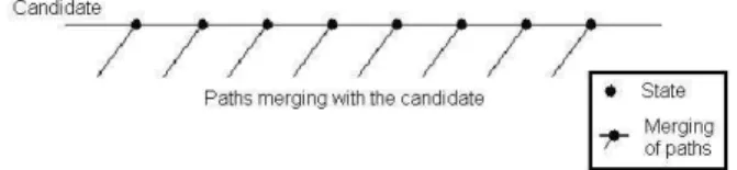
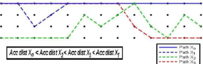
First, before explaining how this search is performed, we define the concept of the minimum alternative path. The
minimum alternative path of the kth candidate is defined as the path merging with the kth candidate that has the minimum final accumulated distance among all the paths
that, at any moment and at any state, merges with the kth
candidate. One scheme representing the paths merging with a candidate is represented on the figure beneath (figure 8).
Figure 8: Possible minimum alternative path - Sequences merging at any state with the candidate
Moreover, searching this minimum alternative path is equivalent to seek the state (travelled by the candidate) where the difference between the current accumulated
distance of the candidate and that of the other path merging on this state is minimal (minimal state
difference). The reason is that the final accumulated
distance of this other path can be calculated adding this
state difference to the candidate final accumulated
distance; therefore the minimal state difference implies the minimal final accumulated distance (see figure 9 below). From now on, we call the state where the candidate and the minimum alternative path merge the
merging state.
Figure 9: Justification of the minimum alternative path selection
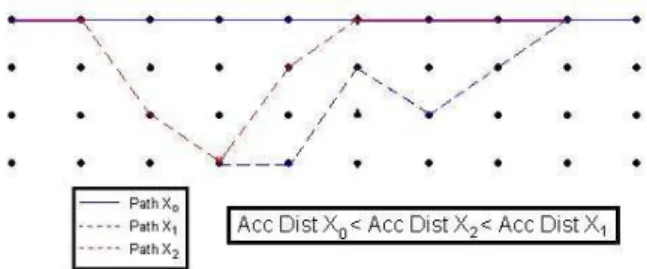
Once the definition of the minimum alternative path has been set, the search of the new candidate i can be presented. The search of the new candidate i is accomplished by searching the minimum alternative path of each existent candidate and selecting among them the one with the minimum accumulated distance. This chosen sequence is the new candidate (ith candidate) because it has the smallest accumulated distance among all the
remaining sequences still not being a candidate. This process would be sufficient if the initial state and the finale state of the word/subframe being decoded were known. However, this is not the case and thus other type of sequences can be the new candidate.
In the case where the initial and final states of the word/subframe are known, all the possible new candidates reach this known final state. Therefore, only the sequences that eventually merge with some old candidate, and thus end at this known final state, can be new candidates [6]. In this paper, the minimum alternative
path of each candidate is the sequence with the smallest
accumulated distance that fulfils this requirement. However, when the final state is not known, any sequence can be a new candidate. Therefore, any sequence surviving all the Viterbi decoding and ending at any state can be a new candidate when the final state is unknown (figure 10). In this paper we call these sequences
survivors and their accumulated distances are directly the
accumulated distances of the Viterbi decoding.
Figure 10: Possible Candidates when the final state is unknown.
To sum up, the search of the new candidate i is done by:
1- Searching among the survivors which are yet not
candidates, the one with the minimum accumulated
distance.
2- Searching the minimum alternative path of each
candidate.
3- Searching between the survivor of the step 1 and the
minimum alternative paths of the step 2 the sequence with the minimum accumulated distance. This sequence is the new candidate i.
4-
An unwritten condition imposed during this process is that each candidate has stored all the state differences of its travelled states in order to allow the identification of its
minimum alternative path. However, this condition is not trivially accomplished. If the previous candidates are not eliminated during the generation of the current new candidate i, they can cause two major complications: first, some previous candidates can eliminate the new candidate
i and thus the recovered sequence is not the searched one.
Second, some previous candidates can eliminate any sequence which could be a potential candidate. Therefore, in order to recover the correct new candidate and correctly store the differences of the states travelled by this new candidate, the previous candidates should be eliminated.
Nevertheless, the elimination of previous candidates can lead to the false conclusion that potential candidates merging with them are lost. This is not the case, because these potential candidates are taken into account during the search of the minimum alternative path of these previous candidates.
G. Generation of the new candidate i:
Before starting with the generation of the new candidate i some definitions are presented. We call the father of the
ith candidate, the candidate from which this ith candidate
was generated. In other words; the ith candidate was a
minimum alternative path of the father. Moreover, this ith
candidate is also called a descendant of the father. Consequently, a survivor does not have a father but can have descendants.
The generation of the new candidate i is achieved by applying again the Viterbi decoding process but forbidding the survival of the previous generated candidates. In other words, only the paths with a smaller
accumulated distance (previous candidates) than the current new candidate should be modified (eliminated at some point) and the other sequences, bigger accumulated
distances, have not to be affected by this new decoding. Therefore, the method proposed in this document in order to generate the new candidate i is:
1- To exactly reproduce its father; the conditions that allowed its generation.
2- To add some restrictions concerning other
descendants of the father that were created between the generation of the father and the generation of this new candidate i.
3- To force the system to select the new candidate
instead of its father at the current merging state. The restriction term will be defined in the following subsection but for now it is only necessary to know that a restriction chooses which path survives between the two paths merging at a state.
The justifications of these 3 points are presented next. Firstly, the exact generation of the father at the moment of its creation: in order to ensure that the new candidate i is exactly the path anticipated during the searching of the
minimum alternative path, the father at the moment of its generation has to be rigorously reproduced. If it is not the case, it is possible that other paths (previous candidates already eliminated at the father’s creation) merge with the new candidate i and, due to its smaller distance, are chosen before him. This means that a previous candidate will be reproduced instead of the new anticipated one. Moreover, if the father at its formation is not exactly reproduced, it is also possible that some sequences X with bigger accumulated distances than the new candidate are erased by previous candidates. Then, since these
candidates are also eliminated later (in order to not select them), these paths X will never be examined and therefore they will be lost (possibilities of losing the correct transmitted sequence). Besides, if the paths are not the expected ones, the state differences are false and the final
accumulated distances are wrongly estimated. To sum up, the exact regeneration of the father at the moment of its creation is required or, in other words, the exact regeneration of the circumstances is necessary (as it seems logical) in order to obtain the new candidate i, to inspect any possible path and to obtain the correct state
difference at the travelled states.
Note that, in order to generate exactly the father at its creation, it is necessary to regenerate rigorously its father at its creation too (the moment where the state differences where calculated). Therefore, the new candidate is found by reproducing all its ancestors at the moment of its creation: the father, the father of the father, the father of the father of the father, etc, until the first candidate is reached.
Second, the restrictions imposed by other descendants of the father: once a candidate is generated, its state
differences (difference of distance between the accumulated distance of the candidate and the one of other path entering the state) are stored. Then, when a new candidate is obtained from this candidate (a minimum
alternative path), it is necessary to mark the state where these two paths merge. The reason is simple: if the state is not marked, it will be selected again as the merging state during the next iteration (search of another new candidate). Therefore an unnecessary repetition occurs and the process enters in a deadlock. Moreover, if the
merging state is marked but it is not taken into account in the generation of the next candidates, it is possible that these new candidates are eliminated when they collide (merge) with a previous descendant of the father entering at this previous merging state (since the descendant has a smaller distance).
An example can be seen on the figure 11, where if the
path X2 is not restricted during the generation of the path
X1 from the path X0, the path X1 will be erased by the
path X2.
Moreover, this same type of restrictions has to be added to the generation of the father of the father (grandfather) in order to obtain the father at its formation. The reason is simple: the father was generated from the grandfather but it cannot be assured that it was its first descendant. Therefore, for the same reason as the restrictions imposed by the other descendants of the father, in order to generate the father and not any other previous descendant of the grandfather these restrictions have to be imposed.
Figure 11: Elimination of the new candidate i from a previous descendant of the father's new candidate i .
Third and last, the imposition of the path entering the
merging state: during the new execution, the system has to impose that at the merging state the path that is not the candidate is eliminated and consequently that the other
path survives. If this imposition is not respected, the path
recovered will be the original candidate from which the new candidate i has to be obtained.
To sum up, in order to generate the new candidate i with all the correct distance differences at each state traveled by it, the system has to execute the Viterbi algorithm with the following restrictions:
• The restrictions avoiding the selection of a previous
descendant of the father instead of the new candidate.
• All the restrictions used to generate its father at the
moment of its creation:
o The restrictions avoiding the selection of a
previous descendant of the father of the father (grandfather) instead of the father.
o All the restrictions used to generate the father of
its father at the moment of its creation: Etc.
• The restrictions avoiding the selection
of a previous descendant of the 1st
candidate instead of the father of the … of the father.
• All the restrictions used to generate the
1st candidate (which are none).
• The restriction that selects the new candidate i
instead of his father on the merging state.
Moreover, after the generation, the system has to add 4 different types of restrictions on the candidates in order to prepare the system generation of the next new candidate: 1- On the father: a restriction signalling that on the
merging state a descendant was generated.
2- On the new candidate: the current restrictions of its
father during the candidate i generation in order to know the circumstances necessary to reproduce it. Note that these restrictions are the restrictions avoiding the selection of previous descendants instead of this new candidate i.
3- On the new candidate: The restriction of the merging
4- On the new candidate: the restrictions contained on the states travelled by the new candidate in order to know from which states a descendant can be generated. It is possible that some candidates have already been generated from these states.
The second type of restrictions serves to recreate the conditions of the generation of the candidate. In fact, if each candidate saves the restrictions of its father at the moment of its generation, its exact reproduction is ensured by recovering these restrictions, plus the same restrictions but that of its grandfather stored on the father, and so on until reaching the first candidate. This statement is justified in the following example:
Example: A candidate k is generated from the 1st
candidate; the restrictions of the 1st candidate used to create the candidate k are stored into the k candidate. Later, a candidate n is produced from the candidate k (n
> k), which means that the restrictions of the 1st candidate
stored into the candidate k are used (recreating the exact situation of candidate k’s generation) plus its current
restrictions (descendants already generated from
candidate k). Then, once the candidate n has been generated, these last current restrictions of the candidate k are stored in the candidate n. Finally, we want to generate a new candidate m from the candidate n (m > n > k); therefore the restrictions to use are: the restrictions of the
1st candidate stored into the candidate k (recreating the situation of the generation of candidate k), plus the restrictions of the candidate k stored into candidate n (once the candidate k is regenerated, these restrictions recreate the situation of the generation of candidate n from the candidate k) and plus the current restrictions of the candidate n (previous generated descendants before the candidate m).
H. Restrictions:
A restriction is an element that determines which sequence between two sequences entering a specific state/time couple has to survive. The restrictions are used in order to privilege some paths over the others and therefore they are used in order to allow a path with a bigger distance than another to survive or to impose some parts of a sequence.
Due to the continuous adding of restrictions on the candidates and the reusing of them (restrictions to generate the fathers), it is possible that the imposition of forcing the survival of the paths with the bigger distance at a specific state/time couple is not enough. In fact, when one of these restrictions is imposed, and the first time that a restriction is imposed is to generate a descendant from its father, its main function is to create two different paths, each one containing one of the paths merging at the state where the restriction is applied (the father and its
descendant). Therefore, if one path is followed by the
father and the other is followed by its descendant; both sequences are candidates and thus the system obtains the inspection of both routes and the possibility of inspecting the paths merging with them. Then, in order to achieve these objectives a restriction consists of 3 elements: the time when it is applied, the merging state (state where it is applied) and the state S-1 from which the survival path enters the merging state.
The application of these restrictions on the search of the new candidate i is the following: the restrictions that have already been used previously in order to obtain another candidate impose that the new candidate at the time t is
the path that enters the merging state S from the state S-1
travelled by this previous candidate (state already known). However, when these restrictions specify that the new candidate merges at this state, they impose that the path to survive at the time t, is the sequence that enters the
merging state S from the state S’-1 that is not travelled by the previous candidate (since it is still not known). Therefore, an additional boolean variable is required to mark which of the paths has to survive.
Finally, note that the second type of restrictions defined during the generation of a new candidate i is the restrictions of the father of this new candidate i and they are saved on the new candidate i itself. This means that each time parameter t, where the father has a restriction, is stored on its descendant, the new candidate i. The other two main definers, S and S-1, of the restriction are not stored. The reason is that from the time t of a candidate restriction, the merging state and the previous merging
state are automatically determined because any candidate follows only one path and this path has already been saved. Therefore, it is possible to determine the states, S
and S-1, only knowing at which time t the father travelled
the state S. Moreover, when the proposed algorithm refers to the recovery of the restrictions of the father stored in its
descendant, the algorithm means that each merging state
S and each previous merging state S-1 of the father referred by each time t stocked on the descendant are obtained, and thus a complete restriction of the father is created from the descendant.
I. Duration of the Viterbi decoding and bit recovery
One of the particularities of the Viterbi algorithm is its duration. Since the input of a convolutional code is a constant flux of symbols, the decoding process cannot wait until the end of the data transmission, which is infinite, before estimating the received symbol values. However, the system can guarantee with a high probability a convergence of their values at a determined moment of the transmission. More specifically, the
Viterbi algorithm can determine the value of the ith
is being received and used to calculate the transition
distance and the accumulated distances of the survivors.
L is the constraint length of the convolutional code; in this case it is equal to 7.
Therefore, in the GPS L2C and GPS L5 navigation messages, the duration of the Viterbi decoding required to ensure the correct demodulation of all the bits constituting a word/subframe is M+5 L; where M is the size of the subframe (300 bits) or the word (30 bits). Moreover, note that the inclusion of 5 L supplementary bits means that in order to decode the word/subframe n, some bits of the word/subframe n+1 (and even n+2 for GPS L2C mode NAV data) have to be received. Therefore only the M bits of the subframe or word are recovered and transformed into information bits.
J. The Algorithm:
The algorithm presented does not include the verification of the outer code since it is widely known.
The algorithm presented bounds the maximum number of iterations (number of candidates) to K before stopping the research and discarding the word/subframe. It is described bellow:
• Initialization:
1. Array of Distances: 2L-1 double values to store the
accumulated distance of all the final states. The states after the reception of the last symbol (M +
5 L).
2. Array of Survivors: 2L-1 booleans to store the
surviving paths of the final states that have already been considered as candidates.
3. Matrix of Differences: (M + 5 L)⋅K double values
to store the state differences which are the differences between the accumulated distances of the candidate and the other path merging at any state for all the states travelled by the candidate. The differences of K candidates are stored.
4. Matrix of Candidates: (M + 5 L)⋅K integers values
to store the travelled states of the K candidates.
5. Matrix of Descendants(M + 5 L)⋅K booleans to
store the descendants of the K candidates.
6. Matrix of Generated: (M + 5 L)⋅K booleans to
mark the descendants of the father of the candidate at the moment of the candidate generation. There are K candidates to store.
7. Array of Accumulated Distances: K doubles values
to store the final accumulated distances of the K candidates.
8. Array of Fathers: K integers values to store the line where the candidate’s father is stored. There are K candidates.
• Searching and creating the 1st Candidate:
1. Execution of the complete Viterbi decoding
process: M + 5 L received symbols.
2. Storing the accumulated distance of each survivor
path (one for each state) at Distances array.
3. Selecting the path with the minimum accumulated
distance as the 1st candidate.
4. Storing the state differences of the 1st candidate on the 1st row of Differences matrix.
5. Storing the states travelled by the 1st candidate in the 1st row of Candidates matrix.
6. Storing the final accumulated distance of the 1st
candidate in the 1st cell of Accumulated Distances array.
7. Store the value -1 in the 1st cell of the Fathers array (marking a no valid father).
• Searching the ith Candidate
1. Loop: k = 1 to last found candidate
1.1. Searching the minimum alternative path for the
kth candidate and that is not yet a descendant. In
other words, searching the minimum state
difference of the kth candidate.
1.1.1. Initializing the minimum difference variable
to big number e.g. 1000000000. 1.1.2. Loop: j = 1 to M + 5 L
1.1.2.1. Verifying that the state travelled at time
j has not already produced a descendant
(inspecting row k column j of
Descendants matrix). If this is the case, the system jumps to explore the next state.
1.1.2.2. Previous verification is successful: the system compares the state difference value stored in the row k column j of the matrix Differences to the minimum
difference variable. If it is smaller, this new difference and its state are stored.
1.1.3. The minimum alternative path of the kth
candidate is defined by:
1.1.3.1. Final accumulated distance: value of
the cell k of the matrix Accumulated
Distances plus the value of the
minimum difference variable.
1.1.3.2. The Merging state S: row k column j of
Candidates matrix
1.1.3.3. The previous merging state S-1: row k
column j-1 of Candidates matrix 1.1.3.4. The final candidate’s state Sf: row k
column M+5 L of Candidates matrix
2. Searching the minimum alternative path with the
smallest accumulated distance among all the
minimum alternative path previously found.
3. Searching the initial survivor path with the
smallest accumulated distance among all the initial
in the Survivors array marks if the sequence is already a candidate.
4. Choosing the sequence with the smallest final
accumulated distance between the 2 paths of the two previous points as the ith candidate.
• Creating the ith Candidate from the minimum
alternative path of the kth candidate:
1. Recovering the restrictions used to generated the kth
candidate:
a. Active Father is the father of the new candidate
to be generated.
b. If Active Father is not the 1st candidate, the system recovers all the restrictions of the father of Active Father that are marked on the
Generated matrix row of Active Father. If Active
Father is the 1st candidate, the research of restrictions is over.
c. Active Father is the father of Active Father.
d. Going to step b.
2. Recovering the restrictions of the kth candidate
signalized in the row k of the matrix Descendants (restrictions of the father). Adding only the restrictions that have not been recovered on the previous point.
3. Adding the restriction where the new candidate
eliminates its father (time, new merging state S and previous state S-1).
4. Storing the father identifier (idf) that marks the row
where the father is stored (in several matrices). 5. Storing the final state of the father Sf.
6. Execution of the Viterbi decoding process. This
generation differs from the normal one because it is modified by the restrictions imposed on the previous points:
6.1. Restrictions used to generated the kth candidate: The restrictions impose that at the time t the survivor path entering the merging state S is the
sequence that comes from the previous state S-1
6.2. Restrictions of the new candidate: The
restriction imposes that at the time t the survivor path entering the merging state S is the sequence that does not come from the previous state S-1.
7. Saving in the ith row of the Candidates matrix the states of the path arriving at the state Sf, the i
th
candidate.
8. Saving in the ith row of the Differences matrix the differences between the current distances of new candidate and these of the other path merging at each state travelled by the ith candidate.
9. Marking in the row k column time (father’s line or
kth candidate line) of the Descendants matrix that this state (merging state) has been used to generate a new candidate.
10. Copying in the ith line of the Generated matrix the
line k (father’s line or kth candidate line) of the
Descendants matrix.
11. Marking in the ith line of the Descendants matrix all the times corresponding to a state travelled by the new candidate where a restriction has been applied.
12. Storing in the ith cell of the Accumulated Distances
the final accumulated distance of the path arriving at the state Sf, the i
th
candidate.
13. Storing at the ith cell of the Father array the ith
candidate father identifier (idf).
Creating the ith Candidate from a survivor path:
1. Identifying the final sate Sf of the survivor.
2. Execution of the complete Viterbi decoding
process: M + 5 L received symbols.
3. Storing the travelled states of the survivor path in
the row i of the Candidates matrix.
4. Storing the distance differences between the
survivor (ith candidate) and the paths merging at the states travelled by it on the ith row of the
Differences matrix.
5. Storing at the ith cell of the Accumulated Distances
the final accumulated distance of the survivor path. 6. Storing at the ith cell of the Father the value -1
marking that the survivor (ith candidate) has no father.
7. Marking the element representing the survivor path
as used on the array Survivors.
V. VARIATIONS OF THE NEW ALGORITHM
The proposed algorithm accepts variations that privilege some aspects of the decoding in relation to others. More specifically, 7 variations separated into 4 groups are presented next. First, the introduction of the a priori bit probabilities forms the first group, a variation which increases the number of correct decoded words; however this modification needs external information (the probabilities). Second, the variation of the maximum number of candidates that increases or decreases the number of correct decoded words. And this last variation also decreases or increases the resources needed by the receiver in order to implement the algorithm. Third, the sliding window, variation which significantly increases the number of correct decoded words while slowing down the decoding process. Finally, the last group of variations speeds up the process at the same time that decreases the number of correct decoded words. Therefore, the two last groups worsen the aspect of the method which is improved by the other last group. However, the improvements are much more significant (in terms of quantity) than the drawbacks; therefore, we explain them in this paper and they have been implemented.
A. Viterbi method with use of bit a priori probabilities
One improvement of the proposed algorithm is the optimization of the traditional Viterbi decoding. It can be accomplished by the estimation of the prior values of the received bits. In that case, only a slight variation of the
transition distance calculation is required to adapt the Viterbi algorithm to the use of a priori bit probabilities. From the fundamental equation of the Viterbi method, the new transition distance is equal to the traditional distance plus an extra term by means of which the Viterbi algorithm takes into account the a priori bit probabilities:
New Trans Dist = Trans Dist -
2
2log
(
(
)
)
K
S
P
⋅
⋅
σ
where: - σ2: Noise Power- P(Sk): Probability of the bit K being equal to the desired value
The bit a priori probabilities used in the simulations in this paper have been calculated from the 2006 and 2007 ephemeris values stocked into the ftp servers referenced by the IGS web page (International GNSS Service). The message content of GPS L5 and GPS L2C mode CNAV data is still not available, therefore only the probabilities for GPS L2C mode NAV data were calculated.
B. Maximum number of candidates or maximum number of Iterations:
This variation is, in fact, a variation of a parameter of the simulation. This parameter is the maximum number of candidates searched by the proposed algorithm before determining the impossibility of finding the correct transmitted word and passing to the decoding of the next one. The influence of the parameter is the following. On one hand, the more candidates are searched, the more correct decoded words the algorithm finds because the size of the group of inspected sequences is bigger. On the other hand, the more candidates are searched, the more often the receiver dwells on the decoding of one word and the more resources are needed (memory, power, etc). Therefore, a compromise between the decoding performance and the required receiver resource in terms of maximum number of candidates has to be found for each application.
C. Sliding Window:
The main algorithm proposes the application of the Viterbi decoding during the length of one word (M symbols) and 5⋅L additional symbols in order to reach convergence of these first M symbols. The technique searches the most probable sequence of length M+5⋅L (candidate) that verifies the outer code. Nevertheless, the
algorithm can search the most probable sequence over N words (N⋅M+5⋅L symbols) since the calculation of the
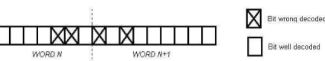
accumulated distance is not interrupted and the final state is not fixed. Obviously, this augmentation of the length of the Viterbi decoding implies an increase of the computational cost of the process because the number of candidates grows exponentially with the number of decoded symbols (N⋅M). Therefore, this variation should be applied only if the gain in terms of amount of correct decoded words is significant. The inspection of the source of errors, why the errors are not corrected, of this proposed decoding technique provides the answer. The source of errors is the limitation of the outer code to detect any possible pattern of errors contained by a coded word. Consequently, the errors after the decoding process are introduced by these wrong words that have passed the verification of the outer code. Two types of error patterns can be differenced inside these wrong words. The first one corresponds to the errors located in the middle of a word. In this case, the principal characteristic of the word is the equality between the initial and final states of the wrong and the correct word. The second type corresponds to the errors located on the edges of a word and either the initial, the final word state or both are different from the ones of the correct word (figure 12).
Figure 12: Pattern of errors situated at the edge of 2 consecutive words.
Therefore, depending on the type of pattern of errors, the decoding of an extra word can correct more wrong words. In fact, when the pattern of errors is situated at the word’s edge, it is quite probable that the candidate verifying the outer code for the 1st word fails the verification for the 2nd
word when the candidate is extended to the end of the 2nd
word. The reason is simple: the probability of two wrong words passing the outer code verification is much smaller than the probability of only one. However, if the pattern of errors is situated at the middle of the word, meaning that the final state of the first wrong word is equal to the correct one, nothing can be done. The justification is simple: if the final state of the 1st word is the same for the correct and the wrong word, the extension of the candidate until the end of the 2nd word is the same for
both; therefore, although the 1st word was wrong, the 2nd
word can contain none error, and this situation is not possible on the edge error pattern case.
Finally, each time that a candidate verifies the outer code (N words), this algorithm variation recovers the M bits of each of the first N-1 words. The bits of the last word are not recovered because the last word can have a pattern of errors localized at its left edge. Therefore, the solution is
to implement a sliding window where the last word is never decoded but is used for the search of the previous candidates: n words made a candidate, only the first (n-1) words are considered as decoded, afterwards the last word plus (n-1) new ones constitute the new candidate and the process begins again. The algorithm is the following:
• ith window:
o Words (i-1)⋅(n-1)+1 to (i-1)⋅(n-1)+n constitute the new candidate
o Search of the candidate constituted by these n
words that verifies the outer code.
o Decoding the bits of the words (i-1)⋅(n-1)+1 to
(i-1)⋅(n-1)+(n-1)
This variation improves considerably the number of correct decoded words for the navigation message GPS L2C mode NAV data; however its implementation has been discarded for GPS L2C mode CNAV data and GPS L5 due to the low probability for the CRC-24Q of missing a wrong word [4].
D. Algorithms speeding up the process:
Banning candidates:
The first and most important consequence of applying any type of improvement that increases the process execution speed is the loss of the capacity of ensuring the system capability of finding the correct transmitted sequence. More specifically, the system can not guarantee the inspection of all the words. Therefore, it exists the possibility that the correct sequence is simply banned before even processing it. Three different types of speed optimizations are proposed:
1- No inspecting the sequences differing on only some
of the last 5⋅L bits (or states) from the path travelled by a wrong candidate: the last 5⋅L bits do not participate on the outer code’s verification.
2- No inspecting the survivors differing on only some of
the last 5⋅L bits (or states) from the path travelled by a wrong survivor: the last 5⋅L bits do not participate on the outer code’s verification.
3- No inspecting the sequences which have the same
accumulated distance as another candidate but have a different father because they have travelled the same paths.
These improvements, specially the third one, proved to greatly speed up the process and the percentage of times that the correct word has been banned is really low.
Imposition of the initial state:
Another way of speeding up the process execution is to impose the initial state of all the possible candidates. In other words, each time that a candidate passes the outer code verification, its final state is used as the next initial one. The problem is, obviously, the imposition of a wrong
state which almost eliminates the possibility of finding the correct transmitted sequence.
However, the few realised tests have not shown any difference of performance between this variation and the normal algorithm.
VI. SIMULATION RESULTS
The objective of the simulations presented in this paper is to evaluate the decoding performance of the new proposed algorithm in comparison with the traditional Viterbi algorithm for the navigation messages GPS L2C and GPS L5. The figures illustrating the results present
the Eb/N0 (Energy per Bit to Noise Power Density Ratio)
required by the different algorithms in order to obtain a determined BER. The results are presented in Eb/N0 levels because it is the typical figure of merit used in channel code and decoding techniques comparisons.
However, a later section will relate the Eb/N0 value with
the C/N0.
The proposed algorithm implemented for these
simulations always includes the variations of the sliding window, the banning candidates and the imposition of the initial state. However, different simulations have been realized in order to display the influence of the two others variations: the use of bit a priori probabilities and the variation of the maximum number of candidates.
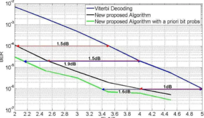
The figure 13 illustrates the decoding performance for GPS L2C mode NAV data with the traditional Viterbi algorithm, the new proposed algorithm and the new proposed algorithm with the use of bit a priori probabilities. The maximum number of candidates for this simulation is 4000.
Figure 13: GPS L2C mode NAV data Decoding Performance: BER vs Eb/N0 for the Viterbi Algorithm, the New Proposed Algorithm
and the New Proposed Algorithm with a priori bit probabilities - 4000 candidates
Figure 13 shows a gain of 1.5dB for high BER values and a gain of 1dB for low BER values between the Viterbi algorithm and the new proposed one. Moreover, the
gain of 1.6dB for a BER equal to 10-6 between the Viterbi algorithm and the new proposed one with bit a priori probabilities. However, the BER for the new algorithm with probabilities has been calculated only over the ephemeris bits because the probabilities have been established for the ephemeris data only.
Besides, it can be observed a decrease of the gain for the high BER values. The justification of this phenomenon is the following: the gain is limited by the outer code that is the extended Hamming (32,26) code. In other words, the percentage of decoded wrong words succeeding the verification of the outer code in relation to the initial number of wrong words (words provided by the traditional Viterbi decoding) decreases with high BER values.
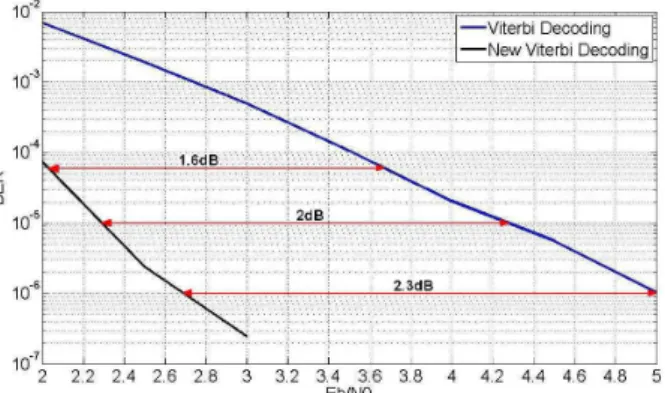
The figure 14 illustrates the decoding performance for GPS L2C mode CNAV data and GPS L5 with the traditional Viterbi algorithm and the new proposed one. The maximum number of candidates for this simulation is also 4000:
Figure 14: GPS L2C mode CNAV data and GPS L5 Decoding Performance: BER vs Eb/N0 for the Viterbi Algorithm and the New
Proposed Algorithm - 4000 candidates
The figure 14 presents a gain of 1.6dB for a BER equal to 5·10-4, a gain of 2dB for 10-5 and a gain of 2.3dB for 10-6 between the Viterbi decoding technique and the new one. Moreover the gain difference between the techniques grows when the target BER decreases. Therefore, it can be observed that the limitation of the outer code, CRC-24Q, is not found in this case which is normal since this code has much better capacity of detection than the extended Hamming (32,26) in terms of detection.
Additionally, the BER value of the new algorithm for an
Eb/N0 equal to 3.5 dB is not presented because the
simulation did not find any error after the decoding of 401999700 bits (1/ 401999700 = 2.4876e-009).
Last, the figure 15 illustrates the decoding performance for GPS L2C mode CNAV data and GPS L5 with the traditional Viterbi algorithm and the new proposed one. In this case, the maximum number of candidates is 50 but
the results of the 4000-candidates case are also displayed in order to allow a better comparison.
Figure 15: GPS L2C mode CNAV data and GPS L5 Decoding Performance: BER vs Eb/N0 for the Viterbi Algorithm and the New
Proposed Algorithm - 50 and 4000 candidates
The results of figure 15 show a gain of 1.1dB for BER equal 10-4, a gain of 1.5dB for 10-5 and a gain of 1.8dB for
10-6 between the Viterbi decoding technique and the new
one with 50 candidates. Moreover, the gain difference between the traditional Viterbi and the new technique with 50 candidates also appears to grow when the target BER decreases.
And finally another important observation extracted from the figure 16 is the gain difference between the 50-candidates and 4000-candiates case with the new proposed algorithm. This gain difference is constant and equal to 0.4/0.5dB meaning that the use of a great amount of candidates (needing a lot of receiver resources) is not necessary to obtain a good decoding performance. Table 1 summarizes the gain in terms of Eb/N0 or C/N0 of the new proposed algorithm in relation to the traditional Viterbi Decoding.
Table 1: Gain difference in Eb/N0 of decoding performance between
the Viterbi Algorithm and the New Proposed Algorithm
VII. C/N0 RESULTS AND TRACKING PROCESS
INFLUENCE
The figure 13, 14 and 15 shows the levels of Eb/N0
required to obtain a determined BER value. However, a more exploitable result from a navigation point of view is
BER Decoding technique
10-4 10-5 10-6
New Algorithm no probs – GPS L2C
NAV – 4000 candidates 1.5dB 1.5dB 1dB New Algorithm with priori probs –
GPS L2C NAV – 4000 candidates --- 1.9dB 1.6dB New Algorithm – GPS L2C CNAV
and GPS L5 – 4000 candidates --- 2dB 2.3dB New Algorithm – GPS L2C NAV and