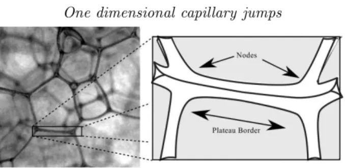
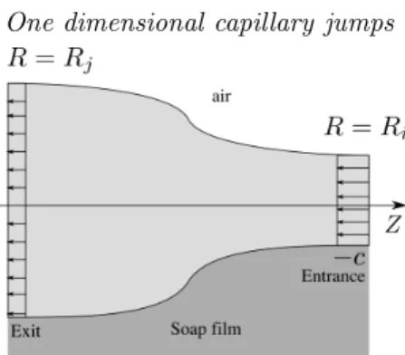
One-dimensional capillary jumps
Texte intégral
Figure
Documents relatifs
As for the time to enter the market, the fast international is the fastest concept to enter the market because the acquired companies are already in operation,
"An Automatic Child-Directed Speech Detector for the Study of Child Language Development." In The 13th Annual Conference of the International Speech Communication
This article characterizes the gradual decay of stabilizability with Reynolds number in the linear complex Ginzburg–Landau model of spatially developing flow systems when a
We initialize the field in |0〉 by first absorbing thermal photons with ∼10 atoms prepared in g and tuned to resonance with the cavity mode (residual photon number ∼
In order to understand how citizens perceive incident reporting systems and which factors affect the user experience (UX), we have performed empirical studies including interviews
At the same time, conversations let the ordering clinician get a better sense of whether another image (or even the first image) is likely to provide useful information.. This is
This work is focused in using fly ash as an alkaline activated cementitious material in hybrid systems with limestone and Portland cement additions to evaluate
Length scales at the free surface are deduced from cross-correlation analysis of wire gauge measurements, and are compared with similar data obtained from images of the
