Publisher’s version / Version de l'éditeur:
Vous avez des questions? Nous pouvons vous aider. Pour communiquer directement avec un auteur, consultez la
première page de la revue dans laquelle son article a été publié afin de trouver ses coordonnées. Si vous n’arrivez pas à les repérer, communiquez avec nous à [email protected].
Questions? Contact the NRC Publications Archive team at
[email protected]. If you wish to email the authors directly, please see the first page of the publication for their contact information.
https://publications-cnrc.canada.ca/fra/droits
L’accès à ce site Web et l’utilisation de son contenu sont assujettis aux conditions présentées dans le site LISEZ CES CONDITIONS ATTENTIVEMENT AVANT D’UTILISER CE SITE WEB.
Canadian Building Digest, 1961-06
READ THESE TERMS AND CONDITIONS CAREFULLY BEFORE USING THIS WEBSITE. https://nrc-publications.canada.ca/eng/copyright
NRC Publications Archive Record / Notice des Archives des publications du CNRC :
https://nrc-publications.canada.ca/eng/view/object/?id=3dde7ed1-cd73-4285-a81a-7ebb0e3ad347
https://publications-cnrc.canada.ca/fra/voir/objet/?id=3dde7ed1-cd73-4285-a81a-7ebb0e3ad347
NRC Publications Archive
Archives des publications du CNRC
For the publisher’s version, please access the DOI link below./ Pour consulter la version de l’éditeur, utilisez le lien DOI ci-dessous.
https://doi.org/10.4224/40000768
Access and use of this website and the material on it are subject to the Terms and Conditions set forth at
Strength of small roofs
Canadian Building Digest
Division of Building Research, National Research Council Canada
CBD 18
Strength of small roofs
Originally published June 1961 W. R. Schriever and H. J. Thorburn
Please note
This publication is a part of a discontinued series and is archived here as an historical reference. Readers should consult design and regulatory experts for guidance on the applicability of the information to current construction practice.
Roofs are required to perform many different functions such as shedding precipitation, limiting heat and vapour flow and resisting loads. The main loads they must resist are snow, wind and dead loads. Sometimes rain and earthquake loads and incidental loads such as those due to workmen or construction equipment also have to be considered. In general, building codes or other standards specify the design values for these loads Which the designer is obligated to use. None the less it is important to understand some of the background to the selection of design loads in building codes in order to gain an appreciation of the over-all problem of the strength of roofs.
Snow Loads
Since for many roofs in Canada the snow load is the greatest load that has to be sustained, its design value takes on great importance with regard to the safety and economy of these structures. Climatic variations across Canada are reflected by the corresponding variations in design snow loads, such as those used in the National Building Code of Canada which vary from 30 to 60 psf in the more populated areas. Even greater loads are required in other areas. The snow loads for parts of Northern Quebec for example reach 90 psf, and loads of up to 100 and 200 psf are found in some of the mountain areas of British Columbia.
In the past, design snow loads were generally based on snow depths on the ground measured at meteorological stations and assumed to be applicable to roofs as a uniformly distributed load. Snow depths on roofs, however, frequently differ from those on the ground through modification by wind, heat loss through the roof and solar radiation. Usually the over-all effect is a reduction of the average load. Certain parts of the roof, however, such as porch roofs and canopies, often accumulate higher than average loads. To investigate this subject a country-wide survey of snow loads on roofs is being undertaken by the Division of Building Research to provide comparisons between average ground loads and loads on different types of roofs varying from ordinary residential roofs to large flat and curved industrial roofs. On the basis of the preliminary results of these observations some improvements have been made in the 1960 edition of the National Building Code of Canada. A small reduction from the ground load was considered justified for the basic roof load, coupled with a provision for a load increase of 50 per cent for roof areas where drifting is likely to lead to snow concentrations. The possibility that snow might slide from one roof onto another or that unsymmetrical loading might develop on curved or pitched roofs is also taken into account.
Wind Loads
Wind can exert large forces on roofs. The greatest forces will be due to suctions rather than pressures. On steep roof slopes facing the wind, pressures are developed, but on most other surfaces, such as roof slopes parallel to the wind, leeward slopes as well as flat and moderately pitched roofs, suctions are developed. Maximum suctions are developed at points of greatest turbulence, such as above leading edges of roofs and near corners where roof coverings may be torn off because of inadequate fastening. Frequently, however, the over-all average wind forces on small roofs are not critical, so that in many cases they are neglected in the design. Strength of Structures
Structural design is essentially a statistical problem. Neither the strength of a structure nor the maximum load to which it will be subjected is predictable with certainty. A small probability of failure is potentially present in all structures and thus it is not possible to achieve absolute safety. All that codes can do is set strength values and design loads in such a way as to reduce the probability of failure to an acceptably low level - It is obvious that the magnitude of the design load has significant bearing on the reserve of strength built into our structures. The second statistical "variable" is the design strength or load-carrying capacity of structures; this will now be considered for small roofs.
Strength of Roofs
Although it may be possible in theory to design roofs in such a way as to "shed" the loads, this is usually not practical, and roofs must therefore be constructed to resist them. This resistance can be achieved from several different actions. On the one hand, a roof built from various elements may act as a complete unit and this unit or "shell" action may contribute substantially to the resistance. In most cases, however, particularly that of small wooden roofs, the greater part of the resistance is provided by the elements acting independently.
Consider first the action of the roof as a unit. The ability of the roof to provide shell or folded plate action is governed primarily by its shape and to some extent its size. For example, a hip or cottage roof represents a potentially stronger shape than a flat or shed roof. The true contribution of shell action is very much dependent on construction details, for if the components which make up the shape are loosely constructed and tied together then any significant contribution of shell action might not appear before some of the elements of the roof approach or reach failure. In other words, the closer the construction can approach a monolithic condition the more likely it is to act as a unit. Nailed, wooden roofs achieve this to a small degree only; the greater portion of the resistance of such a roof to loads is therefore derived from the action of the individual elements.
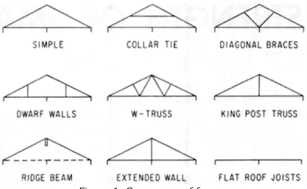
The most important structural elements in a roof are the frames, of which there are four types in common use today: conventional rafter and joist frames, light wooden trusses, ridge support systems and flat roof joist systems. For sloped roofs the conventional rafter and joist system, consisting of a simple triangle of members (Fig. 1), is the most widely used.
Figure 1. Common roof frames
Variations of this include the simple frame augmented by either a collar tie, diagonal braces or dwarf walls. For any sizable span these frames are supported at three points, the third being required to support the joist splice. All these frames work through a basic truss action that is most readily apparent in the simple frame. This action involves a thrust, produced at the heels by the loaded rafters, which must be resisted by the tying action of the ceiling joists. The most important joints are therefore the heel joints and the ceiling joist splices. The bending resistance of the rafter is also a significant part of the frame strength. The secondary members (in variations of the simple frame) are used as intermediate supports to reduce the spans which determine the required rafter sizes. They also have a varying but important effect on the thrust. Member sizes for these frames are normally based on the design load, the span of the frames, the spacing at which the frames are to be used and the species and grade of lumber used. In many building codes these factors are combined in a table which allows a rapid determination of member sizes.
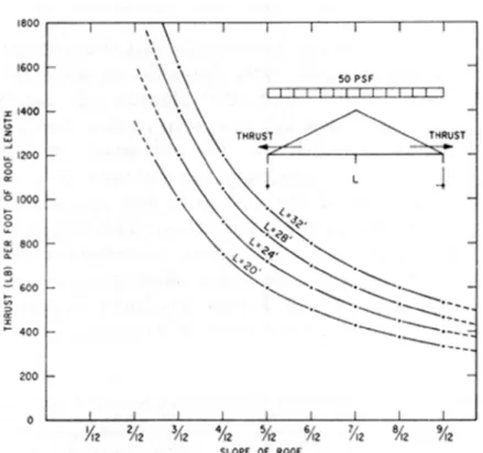
Although this relatively high degree of rationality exists for determining member sizes, the same cannot be said for the nailed connections. Usually the nailing is done according to the customary practice of the carpenter, although there are nailing schedules which specify the number and size of nails required at any particular joint. At the present time neither of these methods is entirely rational. For example, a carpenter, according to custom or the nailing schedule, might use three through nails (driven perpendicularly through the rafter into the joist, as opposed to toe nailing) at the heel joint regardless of the design load, the span and slope of the frame, the spacing of the frames, and the species of lumber. This ignores the obvious fact that there is an increase of thrust with an increase of design load, span and spacing of roof frames and with a decrease of slope (Fig. 2).
Figure 2. Variation of horizontal thrust for a simple frame of various spans under a load of 50 PSF
The nailing at the joints must therefore vary according to these factors. Some building codes have recognized this fact and have expanded their nailing schedules to allow for some of these variables.
There are several other points which require attention. In the variations of the simple frame the nailing of the secondary members should be adequate to prevent seepage at the joints of these intermediate supports. Another point is that collar ties and diagonal braces, when under high load, have a tendency to buckle because they are in compression and unsupported in their weakest direction. This can be prevented either by providing lateral support for the member or by providing a member size whose critical load will not be exceeded.
Trusses
Another type of roof frame which has developed considerably in recent years is the light-weight wooden truss. Trusses, which are usually of either the W- or King Post-type, have three distinct advantages: they give complete freedom to the location of partitions; they allow the builder to enclose the structure more rapidly; they lend themselves to prefabrication.
The design of trusses has evolved on a much more rational basis than that of conventional roof framing. In some cases forces are calculated by normal engineering methods and members and joints are determined on the basis of allowable stresses and loads. In other cases a proof testing system is used in which the truss is designed in part on the basis of calculations and is then load tested to determine whether its performance is acceptable. There are numerous standard designs available, covering many combinations of spans and slopes.* Builders
therefore frequently use these rather than develop their own. The methods of constructing trusses can be quite varied and depend to a large extent on the number to be built. Small numbers are usually built in a simple jig laid out on a convenient surface while larger numbers are mass produced by means of assembly line cutting, jigging and pressing. Connections are made by means of gusset plates or by mechanical connectors such as split-rings and toothed plate devices. When trusses first became widely used gussets were made primarily of plywood,
either nailed or glue-nailed to the members. More recently, there has been a trend towards using metal gusset plates, particularly when the trusses are mass produced.
No-Thrust Systems
Both conventional roof frames and wooden trusses have limitations which lead in part to the use of the third common method of roof framing, the ridge support system. At roof slopes of less than 4 in 12 the thrust which is produced by the rafters of conventional frames becomes so great that it is not practical to provide the number of nails required to resist it. Even if this number were provided, deflections might be excessive. Similarly for low-slope trusses, the strength and stiffness required at the joints is difficult to obtain economically. Nailed and glued plywood gussets provide a solution for this, but the need for careful control of gluing and the difficulties of inspection limit its application. It is here, therefore, that the ridge support system has its place.
The basic principle of the ridge support system is the elimination of thrust by providing a support along the ridge. The roof rafters bear at one end on this support and at the other on the exterior wall, the bearing surfaces being horizontal. Thus the rafters are resisting the load by simple beam action and there is no thrust produced at the heel. The support at the ridge normally takes the form of a beam which may span any distance up to the full length of the roof depending on the available beam support locations. Another method involves the upwards extension of a centre bearing wall to a position where the rafters can bear directly on its top plate. The member sizes required for the ridge support system can be determined from the same considerations as for conventional framing. Since there is no thrust in the ridge support system, the nailing required at the joints is lighter, the main consideration being that of anchorage against the uplift force of the wind.
The flat roof joist system can be considered a variation of the ridge support system and is generally designed on the same basis.
There are other less frequently used methods of framing small roofs, one of which is the post and beam system. As the name implies the system consists of posts or columns supporting beams which in turn support covering materials. The essential difference from other wood framing systems is that the member size and thus the member spacing and spans are considerably larger. Unlike wood-frame construction, post and beam systems are based to a large extent on engineering analysis rather than on convention.
In summary it can be said that the strength required of small roofs depends on the loads to be resisted and the degree of safety desired, and that the provision of this strength depends primarily on the adequacy of the elements. This adequacy depends not only on the strength of the members but equally on the strength of the connections. The design of house roofs is under active investigation by the Division of Building Research, in association with the Forest Products Research Branch of the Department of Forestry.