Custom-fit radiolucent cranial implants for
neurophysiological recording and stimulation
The MIT Faculty has made this article openly available.
Please share
how this access benefits you. Your story matters.
Citation
Mulliken, Grant H., Narcisse P. Bichot, Azriel Ghadooshahy, Jitendra
Sharma, Simon Kornblith, Michael Philcock, and Robert Desimone.
“Custom-Fit Radiolucent Cranial Implants for Neurophysiological
Recording and Stimulation.” Journal of Neuroscience Methods 241
(February 2015): 146-154.
As Published
http://dx.doi.org/10.1016/j.jneumeth.2014.12.011
Publisher
Elsevier
Version
Author's final manuscript
Citable link
http://hdl.handle.net/1721.1/103925
Terms of Use
Creative Commons Attribution-NonCommercial-NoDerivs License
CUSTOM-FIT RADIOLUCENT CRANIAL IMPLANTS FOR
NEUROPHYSIOLOGICAL RECORDING AND STIMULATION
Grant H Mulliken1,*, Narcisse P Bichot1,*, Azriel Ghadooshahy1, Jitendra Sharma1, Simon
Kornblith2, Michael Philcock3, and Robert Desimone1
1McGovern Institute for Brain Research at MIT, Cambridge, MA 02139 2Picower Center for Learning and Memory at MIT, Cambridge, MA 02139 3AnalyzeDirect, Inc., Overland Park, KS 66085
Abstract
Background—Recording and manipulating neural activity in awake behaving animal models requires long-term implantation of cranial implants that must address a variety of design considerations, which include preventing infection, minimizing tissue damage, mechanical strength of the implant, and MRI compatibility.
New Method—Here we address these issues by designing legless, custom-fit cranial implants using structural MRI-based reconstruction of the skull and that are made from carbon-reinforced PEEK.
Results—We report several novel custom-fit radiolucent implant designs, which include a legless recording chamber, a legless stimulation chamber, a multi-channel microdrive and a head post. The fit to the skull was excellent in all cases, with no visible gaps between the base of the implants and the skull. The wound margin was minimal in size and showed no sign of infection or skin recession.
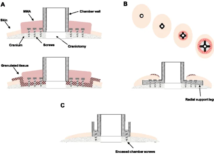
Comparison with Existing Methods—Cranial implants used for neurophysiological investigation in awake behaving animals often employ methyl methacrylate (MMA) to serve as a bonding agent to secure the implant to the skull. Other designs rely on radially extending legs to secure the implant. Both of these methods have significant drawbacks. MMA is toxic to bone and frequently leads to infection while radially extending legs cause the skin to recede away from the implant, ultimately exposing bone and proliferating granulation tissue.
© 2014 Elsevier B.V. All rights reserved.
Corresponding author: Grant H Mulliken, 77 Massachusetts Avenue, 46-6165, Cambridge, MA 02139, [email protected], (617) 324-5530.
*These authors contributed equally to this work
Publisher's Disclaimer: This is a PDF file of an unedited manuscript that has been accepted for publication. As a service to our
customers we are providing this early version of the manuscript. The manuscript will undergo copyediting, typesetting, and review of the resulting proof before it is published in its final citable form. Please note that during the production process errors may be discovered which could affect the content, and all legal disclaimers that apply to the journal pertain.
Conflict of interest
NIH Public Access
Author Manuscript
J Neurosci Methods. Author manuscript; available in PMC 2016 February 15.
Published in final edited form as:
J Neurosci Methods. 2015 February 15; 241: 146–154. doi:10.1016/j.jneumeth.2014.12.011.
NIH-PA Author Manuscript
NIH-PA Author Manuscript
Conclusions—These radiolucent implants constitute a set of technologies suitable for reliable long-term recording, which minimize infection and tissue damage.
1. Introduction
Neuroscientists have developed a wide variety of cranial implant devices for measuring and modulating neural activity in awake behaving mammals. One of the earliest cranial access chambers was developed in the 1950s by Hubel for recording neural activity in the visual cortex of cats [1]. Variants of this chamber design have been broadly adopted in
neuroscience laboratories for more than half a century, and over time, various technological advances have been incorporated to improve implant technology.
Cranial implants used for neurophysiological investigation often employ methyl
methacrylate (MMA) to serve as a bonding agent to secure the implant to the skull (Figure 1A, top). For example, when implanting a standard recording chamber, numerous screws are placed into the bone in the area surrounding the chamber, serving as flanking anchors. The chamber is thus indirectly secured to the skull via acrylic plastic that encases the anchoring screws while adhering to the edges of the implant. Unfortunately, in addition to expanding the overall footprint of the implant, MMA is known to be cytotoxic and ultimately leads to the implant’s long-term degradation [2,3]. Even in the short-term, the polymerization of bone cement during application in surgery yields an exothermic reaction, which produces high temperatures sufficient to lead bone necrosis and tissue damage [4]. Over time, these issues lead to granulated tissue growth between the acrylic and the bone, which is prone to infection and often leads to osteopenia and the failure of an implant due to loosening of anchoring screws (Figure 1A, bottom). Ultimately, this technique thus undermines the longevity and health of the implant, as well as the health of the host animal due to potential chronic infections under the MMA that cannot be cleaned or maintained. Recent, improved cranial implant designs circumvent the need for MMA by making use of radially extending legs or feet to secure the implant to the cranium, which are typically bent manually during surgery to approximate the curved surface of the skull (Figure 1B), though a recent design form-fitted the legs to the skull surface [5]. An undesirable consequence of this approach is that the percutaneous wound margin surrounding the chamber often slides down, or recedes, along the upper surface of the legs [5,6]. The receding skin is believed to be caused by 1) an inability of the skin to bond naturally to the underlying bone due to the raised surface of the leg (e.g., 1.5 mm leg thickness) and 2) due to excessive tension on the overlying skin. Skin recession can lead to exposed bone, which can degrade over time, and also increases the likelihood of an infection as granulation tissue proliferates, jeopardizing the integrity and lifetime of the implant.
Cranial implants used for neurophysiological and neural prosthetics applications are often made from titanium. While titanium implants are bio-compatible and strong, they are known to create artifacts in structural magnetic resonance imaging (MRI), significantly hindering the ability of researchers and clinicians to visualize tissue proximal to the implant. Researchers have alternatively used thermoplastic or ceramic materials for applications involving functional and structural MRI imaging. Over the last several decades,
NIH-PA Author Manuscript
NIH-PA Author Manuscript
polyetheretherketone (PEEK) has emerged as an attractive material for use in spinal fusion, craniomaxillofacial surgery, and various orthopedic applications [7]. PEEK is a
thermoplastic that offers many advantageous properties for the design of bone-mounted implants. In addition to being biocompatible and radiolucent, PEEK can be fabricated to be very strong, especially through the addition of carbon fiber filler. In particular, by filling PEEK with approximately 30% carbon fiber (i.e., carbon-PEEK, Invibio, Inc., Lancashire, UK), its modulus of elasticity can be matched to that of bone, conferring better wear properties and improving the lifetime of load-bearing implants.
Recently, we and others have benefitted from advances in medical imaging and image processing, 3D computer-aided design and CNC (computer numerical control) machining, as well as improvements in thermoplastic biomaterials to implement improved implant designs that enhance the longevity and health of the implant [5,8,9]. For the past six years, we have been using multi-axis CNC machining technology to design innovative carbon-PEEK cranial implants for neurophysiological investigation, which include recording chambers, a head post, and chronic microdrives for recording and stimulation. A key advance has been the ability to machine the base of our implants to be complementary in shape to the underlying portion of the skull, which can be segmented from structural MR images without the need for separate MRI-CT co-registration, as has been previously reported by others [5]. This shaping capability allows implants to be screwed directly to the bone without the need for surrounding MMA reinforcement. In addition, mounting screws could be housed within the walls of the chamber itself, thereby eliminating the need for radially extending support legs, which promotes long-term healing of the wound margin by allowing the skin to attach/bind naturally to the underlying bone around the implant (Figure 1C). These and other design features described below have implications not only for basic scientific investigation, but may also inform the design of medical devices used for long-term recording and stimulation to treat neurological disease.
2. Materials and methods
All aspects of these experiments were carried out in compliance with the National Institutes of Health Guide for the Care and Use of Laboratory Animals and the guidelines of the MIT Animal Care and Use Committee.
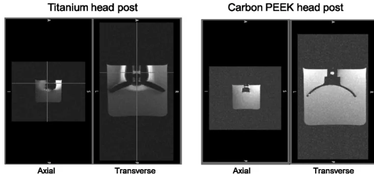
All of the implants described below were made from carbon-reinforced PEEK, unless otherwise mentioned. PEEK has a history of use in FDA approved long term implantable devices since 1999, however, to our knowledge this is the first time that a cranial implant has been made from reinforced PEEK. To illustrate the radiolucency of carbon-PEEK, we performed a phantom MRI scan of a carbon-PEEK head post (Figure 2). The MRI images showed no visible noise or artifact propagated beyond the clearly delineated edge of the implant. In MRI images, the signal intensity of the water surrounding the head post is affected by the distortion of the magnetic field in two distinct ways. Signal reduction can be due to intra voxel de-phasing where the signal intensity decreases as the homogeneity of the magnetic field within a voxel gets poorer. Signal can also be displaced in the so-called "frequency encoding direction" in proportion to the strength of the magnetic field, leading to signal voids near the post and signal "pileup" distally. Therefore, changes seen in the signal
NIH-PA Author Manuscript
NIH-PA Author Manuscript
level surrounding the titanium head post indicate significant distortion of the magnetic field by the head post material.
2.1. General design and manufacturing procedures
2.1.1 MRI—Custom-fit cranial implants were made for craniums of six non-human
primates (rhesus macaque) using the following set of image processing and machining steps. First, the surface curvature of a cranium was derived from a structural magnetic resonance image (MRI) of the animal’s head (images were collected on a whole-body 3T Siemens scanner at the Athinoula A. Martinos Imaging Center at MIT, MP-RAGE sequence, 500 µm isotropic). Note that we found that we could accurately segment the skull and brain using just MR images, avoiding the need for additional acquisition and co-registration of CT data. The software package Analyze (AnalyzeDirect, Inc., Overland Park, KS) was used to segment the cranium from the surrounding soft tissue (brain and skin). Briefly, after segmenting the skull surface, a 3D target vector was placed on the skull at a precise stereotaxic coordinate to define the desired position and orientation of the implant on the skull (the vector could also be used to visualize the projected path of an inserted electrode, for example). Then, the co-registered skull and target vector objects were exported from Analyze into a stereolithography computer-aided design (STL-CAD) compatible file format. A step-by-step video of the image processing steps used to segment the skull, design the target vectors and export to STL format is available in the supporting information (Analyze protocol: Document S1 and Videos S1 and S2). In addition, we have uploaded an example macaque structural MRI (DICOM format) dataset and its corresponding extracted STL files containing the skull, brain and target vector objects (S_J_030410.X).
2.1.2 CAD and CAM—The STL skull file was then imported into a CAD software program (e.g., PowerShape, Delcam, UK) where the skull model was smoothed. The implant was customized to have a base with a contact surface that is complementary in shape to the surface of the cranium at a location and orientation defined stereotaxically by the target vector. Essentially, the unshaped template implant (e.g., chamber, head post) was slid down along the target vector and material was subtracted away from its base so that it matched the underlying skull curvature.
For manufacturing, the customized implant designs were imported into a computer-aided machine (CAM) software program (PowerMill, Mastercam, Tolland, CT), which was used to generate machining tool paths in 3D (XYZ coordinates) or 5D (XYZ coordinates A,B rotary and tilt). Tools paths were post-processed into G-code programs that were used to machine the part from carbon-PEEK stock. CAD and CAM processing was performed in the MIT BCS and Central machine shops.
3. Results
The following is a list of chronically implantable cranial implant devices we have made from carbon-PEEK using structural MRI-based reconstruction of the skull, which are described in detail in the following sections:
NIH-PA Author Manuscript
NIH-PA Author Manuscript
- Recording chamber, which provides access to the underlying brain through a craniotomy.
- Miniature stimulation chamber for chronic implantation of stimulating electrodes.
- Multi-electrode microdrive for chronically recording from up to 64 electrodes simultaneously.
- Head post for fixing the position of the head during behavioral experiments.
3.1. Recording Chamber
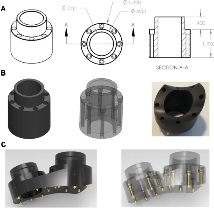
A recording chamber is a commonly used device that provides access to the brain (via a craniotomy) for neurophysiological investigation. Our carbon-PEEK recording chamber is a cylindrical design with an outer diameter of 32 mm and an inner diameter of 19 mm, 8 counter-sunk guide holes with associated screws, and a cap for sealing the top opening (Figure 3). An important feature of the design is that the guide holes for the screws are encased within the wall of the chamber itself. This feature eliminates the need for protruding legs to secure the chamber to the skull (used by existing recording chamber designs) and instead allows for a smooth, uninterrupted interface between the outer edge of the device and the percutaneous wound margin. This method maximizes the contact area between the skin and the bone proximal to the implant in an effort to reduce skin recession and promote a healthy, infection-free margin.
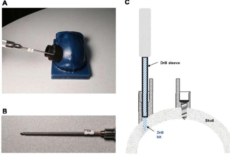
The encased screw holes also allow for straight and stable drilling of screw holes into the bone (as well as insertion of screws) by providing a tight, linearly constrained guide path. Specifically, this was facilitated in surgery by using cylindrical drill sleeves that slide freely inside the chamber holes and prevent slippage or travel of the drill bit on or within the bone and which also control the maximum depth to which each screw hole can be drilled. Importantly, these sleeves (made from stainless steel hypodermic tubing) ensure a precisely-sized screw hole, which maximizes the purchase of the self-tapping screw (see Figure 4). Indeed, we found that this setup even allows for insertion of screws into the bone at oblique angles of approach (e.g., 45 degree angle) without slippage or travel of the drill bit. As a result, this capability also avoids the need to extend the chamber design outward (to accommodate surface normal screw orientations), minimizing the overall area occupied by the chamber’s base.
The average height of the chamber is roughly 20 mm, but may vary considerably at different points along its perimeter depending upon the curvature of the underlying skull and the orientation of the chamber (for instance, it may be desirable to orient the chamber at angles other than surface normal when targeting particular brain structures, such as for LIP). To avoid the need for multiple screw lengths, a single screw length of 12 mm was chosen (Titanium, self-tapping 2.4 mm diameter, Veterinary Orthopedic Implants, FL), which requires that each screw’s guide hole be counter-sunk in advance, during the CAD design process, so that every screw extends 2.5 mm beyond the base of the chamber into the skull (note that it may be advantageous for the screws to protrude more than 2.5 mm in situations
NIH-PA Author Manuscript
NIH-PA Author Manuscript
where the screw enters the bone at an oblique angle or possibly less than 2.5 mm if the measured skull thickness indicates to do so).
Five monkeys (9 chambers) were implanted using these techniques and this design. In all cases, the fit to the skull was excellent, with no visible gaps in surgery (i.e., did not exceed 100 microns). After more than 2 years of implantation in two animals, we did not observe any skin recession (skin continued to adhere to the bone up to the boundary of the chamber implant). In addition there was no sign of infection along the skin boundary of the implant, with minimal granulated tissue present at the skin margin (~0.5 mm).
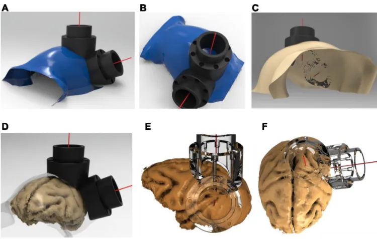
Figure 5A–C illustrates an example segmented skull from one monkey, with the
corresponding target vectors and chambers positioned over the intraparietal sulcus (IPS) and visual area V4 of the macaque. For the same monkey, Figure 5D–F illustrates the implants superimposed on the segmented brain, which verifies the desired placement of the two interlocking chambers over areas V4 and LIP.
3.2. Stimulation chamber
The carbon-PEEK stimulation chamber was designed for bilateral stimulation of reward-related structures of the brain (e.g., nucleus accumbens, VTA) near the midline [10]. Like the recording chamber, the guide holes for the screws are encased within the wall of the chamber itself, preventing the need for the use of protruding feet for securing the chamber to the skull and instead allowing for a smooth and uninterrupted interface between the edge of the device and the skin margin. The chamber consists of a rectangular base with rounded edges, measuring 16.5mm × 15mm on the outside, and with two enclosed 3.6 mm square openings for housing grids. Each grid contains four through guide holes to align stimulating electrodes with brain structures underneath. Four counter-sunk guide holes with associated screws and a lid for sealing the top opening complete the chamber (Figure 6). The height of the chamber is roughly 20 mm, but may vary significantly at different points along its perimeter depending upon the particular curvature of the underlying skull and orientation of the chamber on the skull. The curvature of the skull is derived using the technique described above for the recording chamber. The screw length is 12 mm, which necessitates that each screw guide hole be counter-sunk so that screws extend approximately 2.5 mm beyond the base of the chamber, and into the skull.
3.3. Chronic microdrive
The multi-channel microdrive in Figure 7 is designed to fit snugly inside of the recording chamber described in Figure 3 and can be used for chronic (weeks to months) or acute (daily) neurophysiological recordings, similar in functionality to other commercially available designs [11–16]. The base of the microdrive consists of an array of guide holes (350 µm diameter, spaced 500 µm apart) located at the base of the drive, which provide supporting channels to guide the microelectrodes into the underlying brain tissue. The base of the microdrive can also be shaped to conform to the underlying brain surface (which is also segmented in Analyze software and co-registered to the skull surface, Supporting information Video S3). For example, when targeting brain structures using a non-surface normal approach (such as LIP), it is desirable to contour the base of the microdrive grid in
NIH-PA Author Manuscript
NIH-PA Author Manuscript
order to avoid gaps between the grid’s base and the surface of the brain (or dura). Fitting the brain surface to the array of grid holes helps prevent buckling of the electrodes during insertion.
Microelectrodes are typically back-loaded through chosen grid holes into the interior of the drive and then secured to shuttles located around the perimeter of the drive. Polyimide tubing can be used to ensure a snug fit between the electrode (which can vary in diameter, 150 µm Iridium electrodes were used for our chronic application) and the grid hole, while allowing sufficient space for the electrode to slide freely within the tubing. In addition, by extending the length of the polyimide tubing inside the body of the drive, silicone can be applied to seal and support the tubing as well as to seal unused guide holes. Each shuttle can be advanced downward into the brain or retracted upward using a screwdriver that rotates the shuttle assembly on a threaded stainless steel (or carbon-PEEK, for MRI compatibility) rod. The current design contains 8 shuttles, with a shuttle capable of holding up to 4 electrodes. However, the number of shuttles/electrodes can be scaled up to 64 or more if a higher density is required as demonstrated in Figures S1–S3. The back end of each electrode is wired to a VIA hole of an annulus-shaped printed circuit board (PCB) that is mounted to the top of the drive (Figure. Specifically, one end of 30-gauge copper wire is soldered to the PCB VIA pad and the other end is soldered to a female copper receptacle (Mill-Max, Inc., NY) using a solder sleeve (Raychem, Inc., CA), which is then crimped onto the back end of the electrode and further secured using silver paste, if necessary. The PCB interconnect simply routes the signal from the electrode VIAs to the pins of the surface-mounted Omnetics connectors, a standard connector used in many neurophysiological data acquisitions systems for interfacing to front-end pre-amplification and filtering hardware. Carbon-PEEK microdrives were used to target surface cortex in visual area V4 and the IPS in the parietal lobe). An example of the V4 drive positioned inside of its V4 chamber is shown in Figure 7 (lower right). The drive’s outer wall rests over the chamber wall and is securely anchored to the chamber wall using several set screws. During surgery, the drive is lowered until it makes slight contact with the dura. Other than the 150 µm electrodes, 36 gauge connecting wire, and the PCB interconnect and VIAs, the entire microdrive design can be made from carbon-PEEK and is largely compatible with structural MRI scans. Another attractive feature of using carbon-PEEK for a microdrive is its conductive properties, which allow the chassis to serve as a faraday cage for reducing noise
contamination encountered early in the signal pathway due to electromagnetic interference (a significant issue when recording extracellular potentials in the microvolt range). In particular, the most vulnerable part of the signal pathway is the segment prior to
amplification (i.e., the electrode itself, the connecting wire and the PCB interconnect), which in our design is contained entirely within the drive chassis and can be fully shielded during recordings by applying an enclosing cap on the top of the drive that leaves small openings for head stage cables to plug into the PCB-mounted Omnetics connectors.
3.4. Head post and load-bearing implants
Our technique of shaping implants to the skull based on MRI segmentation can also be applied to head fixation implants that are used in experimental situations that require careful
NIH-PA Author Manuscript
NIH-PA Author Manuscript
control and measurement of head and eye position or when performing tethered neural recordings. To date, head posts have been made primarily out of titanium and typically employ radially extending support legs. Typically, titanium head post legs are machined to be straight and are then bent using orthopedic bending bars, a time-consuming and relatively imprecise procedure. Therefore, we first designed a legged titanium head post that was machined to conform to the skull at a particular stereotaxic coordinate using identical procedures to those described above for the chamber (Figure S4). The design consists of a central post and four radially-extending legs (or straps); each leg has 3–4 evenly spaced screw holes for mounting the head post to the skull. The thickness of each leg is 1.5 mm, and the span of the head post legs is approximately 5 mm across. During implantation, the post was positioned on the skull manually and was observed to fit (or ‘lock into place’) in only a single position, with no visible gaps after placement. The custom-fit nature of our implants greatly simplified the surgical procedure. Implanting an acrylic-free titanium head post requires intraoperative bending to fit the post to the skull, which can take an hour or more, before the post can be fixed to the skull. Implanting our pre-fit titanium head post required only the installation of bone screws. Furthermore, a much closer fit can be achieved by custom fitting the head post to the skull than can by bending the legs (especially near that base of the post where significant gaps can remain). In the same surgery, we also implanted custom-fit chambers over areas LIP and V4. While fabrication of the chambers only requires the use of a 3-axis translation CNC machine, the head post requires a 5-axis CNC machine. These two additional rotating axes allowed us to machine each screw hole to be exactly surface normal to the skull at its point of entry through the base of the head post. Driving each screw into the bone with a straight, surface normal approach maximizes the purchase of the screw into the bone, minimizes shear forces on the implanted screw, and affords
maximal strength to the implant.
A problem that arises when using legged titanium designs is the occurrence of noisy distortions and artifacts when acquiring structural MR images to visualize underlying brain tissue. For experiments using functional MRI, any use of metal is detrimental to data acquisition and such studies typically have used plastic head posts with ceramic screws encased in MMA. As mentioned above, carbon-PEEK is radiolucent to X-ray, CT and MRI scans, and enables investigators to view underlying and surrounding tissue without
occlusion or obstruction. Therefore, we propose a legless carbon-PEEK head post combined with the use of ceramic screws to constitute a radiolucent implant (illustrated in Figure 8). This design will also have other benefits. Given that the surface of the skull can be matched accurately using the above-mentioned methods, we can modify the legged base to have a continuous surface that conforms to the skull, which will not suffer from skin recession and will have increased overall strength relative to a legged design. In addition, the continuous surface design benefits from increased surface area through which additional screw holes can be placed to more strongly secure the head post to the skull.
Bone is known to integrate very well with titanium, often growing around titanium implant structures, and in the case of legged head posts, even growing over the top of the leg surfaces over the course of months to years. This enhanced bonding greatly enhances the strength of titanium implants and leads to longer lifetimes than implants made from other metals. Various techniques for modifying the implant surface microstructure as well as for
NIH-PA Author Manuscript
NIH-PA Author Manuscript
applying coatings to enhance angiogenesis during osseointegration (e.g., hydroxyapatite) have been used to improve the strength of load-bearing implants [17]. One recent promising study demonstrated that the bioactivity of PEEK could be enhanced by seeding human osteoblasts onto PEEK surfaces that were modified by neutral atom beam techniques, increasing osseointegration [18]. These approaches should synergize well with our form-fitting design technique. For example, on average, we found that the head post conformed very closely to the skull, which could potentially accelerate and enhance osseointegration. Furthermore, eliminating the use of bending bars during surgery prevents inadvertent flaking and removal of osteoconductive coatings that occur during bending of legged designs. Ongoing and future studies across laboratories will need to be carried out to assess the effectiveness of surface treatments for enhancing osseointegration with carbon-PEEK head posts. Given the load-bearing nature of a head post implant, we recommend designing carbon-PEEK head posts with a thicker base than would be used for titanium designs (e.g., 10 mm, instead of 1.5 mm used for titanium), to avoid potential fracture.
4. Discussion
We have described a set of chronically implantable devices for neurophysiological investigation in non-human primates. The designs are made using a radiolucent carbon-PEEK material that has several properties that make it attractive for this application. In addition, by eliminating the need for supporting legs and/or the use of MMA for securing implants, we have resolved the skin recession problem that commonly leads to infection in chronic implantation and implant failure while also reducing the overall footprint occupied by these implants. Improvement in the health of the chamber could also be beneficial to two-photon imaging applications in rodents and non-human primates, in particular those experiments that use recording chambers with artificial dura [19]. More generally, we anticipate that the flexibility in design of our approach will inevitably lead to more complex implant designs, capable of jointly accessing increasing numbers of brain regions (so far, we have implanted 3 chambers and 1 head post, at once). Finally, our chamber and microdrive designs could be adapted to build implant designs that incorporate optogenetic devices for both measuring and manipulating neural activity with light, as has been done recently in the mouse [20].
Beyond an immediate application to basic research, the methodologies presented here have the potential to be of benefit to the design of clinical applications. Indeed, the growing fields of neural prosthetics and brain-machine interfaces will benefit from robust, MRI-compatible implants for chronically accessing brain tissue to treat neurological disorders. In addition, the well-established treatment for Parkinson’s disease, deep-brain stimulation (DBS), has paved a path for treating other neurological disorders using electrophysiological brain stimulation. Future DBS advances that promise to incorporate closed-loop, recording plus stimulation, strategies may require multiple cranial implants that access cortical and subcortical brain regions and that house instrumentation for signal conditioning [21,22]. Cranial implants made from carbon-PEEK offer many advantages over existing titanium (and other thermoplastic) cranial implants, as discussed above. Titanium pedestal designs, used to house connectors for subdural multi-electrode arrays (e.g., Blackrock, Inc.) could alternatively be made from carbon-PEEK [23,24]. Corresponding electronics could be
NIH-PA Author Manuscript
NIH-PA Author Manuscript
housed in implantable PEEK and carbon-PEEK enclosures, where conductivity of the chassis could be controlled by the doping percentage of carbon.
Supplementary Material
Refer to Web version on PubMed Central for supplementary material.
Acknowledgements
This work was supported by grants from the National Eye Institute (EY017291, EY017292) and an NRSA Award to GHM (EY020692). We thank Brian Rogers, Jose Estrada and Andrew Gallant for CAD design and CNC expertise, Kostas Tomadakis and Andrew Ryan for machining expertise and Mike Walsh for electronics design. We thank Ellen Degennaro, Erica Pino, Matthew Heard, Jonathan Winkle and Grant Pielli for animal care.
References
1. Hubel DH. Single Unit Activity in Striate Cortex of Unrestrained Cats. Journal of Physiology-London. 1959; 147:226. &.
2. Treon JF, Sigmon H, Wright H, Kitzmiller KV. The Toxicity of Methyl and Ethyl Acrylate. Journal of Industrial Hygiene and Toxicology. 1949; 31:317–326. [PubMed: 15393974]
3. Dahl OE, Garvik LJ, Lyberg T. Toxic Effects of Methylmethacrylate Monomer on Leukocytes and Endothelial-Cells in-Vitro. Acta Orthopaedica Scandinavica. 1994; 65:147–153. [PubMed: 8197846]
4. Dunne NJ, Orr JF. Curing characteristics of acrylic bone cement. Journal of Materials Science-Materials in Medicine. 2002; 13:17–22. [PubMed: 15348199]
5. McAndrew RM, VanGilder JLL, Naufel SN, Tillery SIH. Individualized recording chambers for non-human primate neurophysiology. Journal of Neuroscience Methods. 2012; 207:86–90. [PubMed: 22498201]
6. Pfingst BE, Albrektsson T, Tjellstrom A, Miller JM, Zappia J, et al. Chronic Skull-Anchored Percutaneous Implants in Non-Human Primates. Journal of Neuroscience Methods. 1989; 29:207– 216. [PubMed: 2796394]
7. Kurtz SM, Devine JN. PEEK biomaterials in trauma, orthopedic, and spinal implants. Biomaterials. 2007; 28:4845–4869. [PubMed: 17686513]
8. Adams DL, Economides JR, Jocson CM, Parker JM, Horton JC. A watertight acrylic-free titanium recording chamber for electrophysiology in behaving monkeys. Journal of Neurophysiology. 2011; 106:1581–1590. [PubMed: 21676928]
9. Adams DL, Economides JR, Jocson CM, Horton JC. A biocompatible titanium headpost for stabilizing behaving monkeys. Journal of Neurophysiology. 2007; 98:993–1001. [PubMed: 17522180]
10. Bichot NP, Heard MT, Desimone R. Stimulation of the nucleus accumbens as behavioral reward in awake behaving monkeys. Journal of Neuroscience Methods. 2011; 199:265–272. [PubMed: 21704383]
11. Yamamoto J, Wilson MA. Large-scale chronically implantable precision motorized microdrive array for freely behaving animals. Journal of Neurophysiology. 2008; 100:2430–2440. [PubMed: 18667539]
12. Nichols AM, Ruffner TW, Sommer MA, Wurtz RH. A screw microdrive for adjustable chronic unit recording in monkeys. Journal of Neuroscience Methods. 1998; 81:185–188. [PubMed: 9696324]
13. Lansink CS, Bakker M, Buster W, Lankelma J, van der Blom R, et al. A split microdrive for simultaneous multi-electrode recordings from two brain areas in awake small animals. Journal of Neuroscience Methods. 2007; 162:129–138. [PubMed: 17307256]
14. Gray CM, Goodell B, Lear A. Multichannel micromanipulator and chamber system for recording multineuronal activity in alert, non-human primates. Journal of Neurophysiology. 2007; 98:527– 536. [PubMed: 17493924]
NIH-PA Author Manuscript
NIH-PA Author Manuscript
15. Fee MS, Leonardo A. Miniature motorized microdrive and commutator system for chronic neural recording in small animals. Journal of Neuroscience Methods. 2001; 112:83–94. [PubMed: 11716944]
16. Cham JG, Branchaud EA, Nenadic Z, Greger B, Andersen RA, et al. Semi-chronic motorized microdrive and control algorithm for autonomously isolating and maintaining optimal extracellular action potentials. Journal of Neurophysiology. 2005; 93:570–579. [PubMed: 15229215]
17. Le Guehennec L, Soueidan A, Layrolle P, Amouriq Y. Surface treatments of titanium dental implants for rapid osseointegration. Dental Materials. 2007; 23:844–854. [PubMed: 16904738] 18. Khoury J, Kirkpatrick SR, Maxwell M, Cherian RE, Kirkpatrick A, et al. Neutral atom beam
technique enhances bioactivity of PEEK. Nuclear Instruments & Methods in Physics Research Section B-Beam Interactions with Materials and Atoms. 2013; 307:630–634.
19. Arieli A, Grinvald A, Slovin H. Dural substitute for long-term imaging of cortical activity in behaving monkeys and its clinical implications. Journal of Neuroscience Methods. 2002; 114:119– 133. [PubMed: 11856563]
20. Siegle, JH.; Carlen, M.; Meletis, K.; Tsai, LH.; Moore, CI., et al. Chronically Implanted Hyperdrive for Cortical Recording and Optogenetic Control in Behaving Mice. 2011 Annual International Conference of the Ieee Engineering in Medicine and Biology Society (Embc); 2011. p. 7529-7532.
21. Rosin B, Slovik M, Mitelman R, Rivlin-Etzion M, Haber SN, et al. Closed-Loop Deep Brain Stimulation Is Superior in Ameliorating Parkinsonism. Neuron. 2011; 72:370–384. [PubMed: 22017994]
22. de Hemptinne C, Ryapolova-Webb ES, Air EL, Garcia PA, Miller KJ, et al. Exaggerated phase-amplitude coupling in the primary motor cortex in Parkinson disease. Proc Natl Acad Sci U S A. 2013; 110:4780–4785. [PubMed: 23471992]
23. Huang, R.; Pang, C.; Tai, YC.; Emken, J.; Ustun, C., et al. Integrated parylene-cabled silicon probes for neural prosthetics. Mems 2008: 21st Ieee International Conference on Micro Electro Mechanical Systems, Technical Digest; 2008. p. 240-243.
24. Hochberg LR, Serruya MD, Friehs GM, Mukand JA, Saleh M, et al. Neuronal ensemble control of prosthetic devices by a human with tetraplegia. Nature. 2006; 442:164–171. [PubMed: 16838014]
NIH-PA Author Manuscript
NIH-PA Author Manuscript
Figure 1. Traditional chamber implant complications and improved design
A. Traditional chamber design that uses MMA to encase flanking anchor screws (upper
panel). Over time, granulated tissue (red-circles) grows along the wound margin and beneath the MMA where bone becomes eroded, providing a pathway for infection, and ultimately weakening the implant strength (lower panel). B. Skin recession occurs in legged chamber designs. Following implantation, the skin is tightly closed around the base of the implant (far left). 3–12 months post-implantation the skin recedes, first exposing the implant legs (left-middle) and eventually leading to larger exposed portions of the implant and the underlying bone and potentially leading to an inflamed or enlarged wound margin. A cross-section of the legged chamber design showing early skin recession is illustrated in the lower panel. C. Cross section of improved, skull-fitted chamber design with anchoring screws encased inside the chamber walls to prevent skin recession and avoiding the use of MMA.
NIH-PA Author Manuscript
NIH-PA Author Manuscript
Figure 2. Comparison of MR signal distortion around head posts made of titanium (left) and carbon PEEK (right)
Two views (axial and transverse) of MPRAGE scan using a Siemens 3T MR scanner taken at 390 um isotropic. The total scan time was 2 hours 20 minutes for 8 averages. The head posts had similar geometry.
NIH-PA Author Manuscript
NIH-PA Author Manuscript
Figure 3. Recording chamber design
A. Chamber design template prior to shaping (dimensions in inches), showing perspective
and cross sectional views. B. Solid and transparent views of pre-formed chamber (left, middle) as well as bottom-view (right) of carbon-PEEK machined custom-fit LIP chamber (which interlocks with an adjacent V4 chamber). C. Solid and transparent views of dual chamber implants designs that were placed over V4 and prefrontal cortex, with straight adjoining edge to allow for a smooth wound margin.
NIH-PA Author Manuscript
NIH-PA Author Manuscript
Figure 4. Drill bit sleeves enable straight drilling and maximize screw purchase
A. Image illustrating use of driver sleeve, which supports the drill bit and fits snugly within
the chamber’s screws hole. This mechanism guarantees a linear screw path into the bone and prevents slippage of the bit on the bone, irrespective of the angle of approach (e.g., for the oblique angle shown here). Bottom image shows a close-up of the sleeve used to allow for a 5 mm hole depth. B. Cross-section of chamber wall, illustrating the use of the drill bit sleeve assembly, during drilling (left) and after a screw has been inserted (right).
NIH-PA Author Manuscript
NIH-PA Author Manuscript
Figure 5. Skull-surface matched head post and dual-chamber system (V4 and LIP)
A–B. Smoothed segmented skull (blue) created using the Analyze software and rendered in
PowerShape software, along with V4 and LIP implants. The red line stemming from the center point of each chamber depicts the target vector, which was also generated in Analyze.
C. Bottom-view of skull, demonstrating the contoured fit of the base of the chambers to the
skull. D. Smoothed skull surface rendered transparent to illustrate relative locations of brain and skull surfaces to superimposed chambers. E–F. Co-registered brain and transparent chambers illustrate accurate targeting of brain structures. Lower-right quadrant visual field representation is targeted in area V4 (E), with the center of the chamber aimed between the lunate and superior temporal sulcus. Intraparietal sulcus and area 5 are targeted in a chamber placed over the posterior parietal cortex, used for a dorsal approach to area LIP (F).
NIH-PA Author Manuscript
NIH-PA Author Manuscript
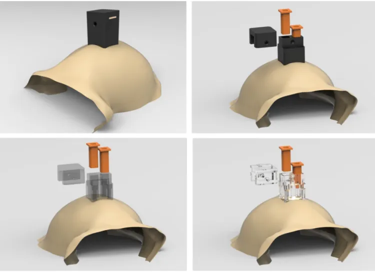
Figure 6. Stimulation chamber design
The drawings illustrate the chamber with all of its parts in place (top left) and in exploded views where the individual parts of the chamber are fanned out in space (i.e., lid, two grids, and main body of the chamber).
NIH-PA Author Manuscript
NIH-PA Author Manuscript
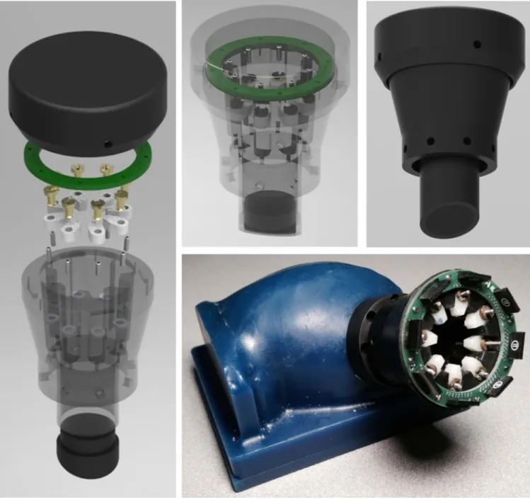
Figure 7. Chronic microdrive design
Exploded view of 8-shuttle microdrive used for recordings in area LIP (left) as well as an assembled view of microdrive rendered transparent (top middle). A solid view shows the carbon PEEK drive fully assembled with its cap in place (top right). Finished 8-shuttle drive inserted into a custom-fit chamber over area V4 on wax skull model (bottom right).
NIH-PA Author Manuscript
NIH-PA Author Manuscript
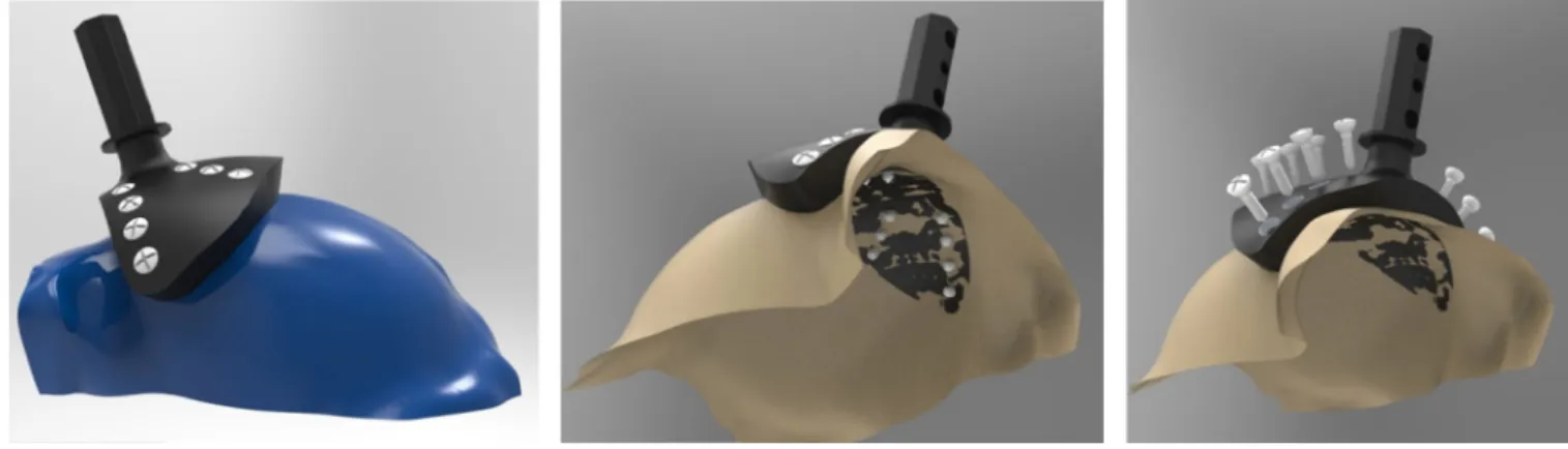
Figure 8. Custom-fitted head post designs
Example carbon PEEK head post design that conforms to anterior portion of the skull, demonstrating the ability to accurately design parts that match a large area of the cranium (ceramic screws are shown). Each screw hole has its own independent axis that allows it to be drilled surface normal to the skull surface (right).