HAL Id: hal-02937660
https://hal.archives-ouvertes.fr/hal-02937660
Submitted on 14 Sep 2020HAL is a multi-disciplinary open access archive for the deposit and dissemination of sci-entific research documents, whether they are pub-lished or not. The documents may come from teaching and research institutions in France or abroad, or from public or private research centers.
L’archive ouverte pluridisciplinaire HAL, est destinée au dépôt et à la diffusion de documents scientifiques de niveau recherche, publiés ou non, émanant des établissements d’enseignement et de recherche français ou étrangers, des laboratoires publics ou privés.
On a Two-Dimensional MoS2 /Mo2CTx Hydrogen
Evolution Catalyst Obtained by the Topotactic
Sulfurization of Mo2CTx MXene
Mohamed Benchakar, Varun Natu, Tarek Ali Elmelegy, Maxim Sokol, Joshua
Snyder, Clément Comminges, Cláudia Morais, Stéphane Célérier, Aurélien
Habrioux, Michel Barsoum
To cite this version:
Mohamed Benchakar, Varun Natu, Tarek Ali Elmelegy, Maxim Sokol, Joshua Snyder, et al.. On a Two-Dimensional MoS2 /Mo2CTx Hydrogen Evolution Catalyst Obtained by the Topotactic Sulfurization of Mo2CTx MXene. Journal of The Electrochemical Society, Electrochemical Society, 2020, 167 (12), pp.124507. �10.1149/1945-7111/abad6e�. �hal-02937660�
On a Two-Dimensional MoS2/Mo2CTx Hydrogen Evolution Catalyst Obtained by the
Topotactic Sulfurization of Mo2CTx MXene
Mohamed Benchakar1, Varun Natu2, Tarek Ali Elmelegy2, Maxim Sokol2, Joshua Snyder3, Clément Comminges1, Cláudia Morais1,Stéphane Célérier1,z, Aurélien Habrioux1, z, Michel W. Barsoum2,z
1. Institut de Chimie des Milieux et Matériaux de Poitiers (IC2MP), Université de Poitiers, CNRS 4, rue Michel Brunet, F-86073 Poitiers, France
2. Department of Materials Science and Engineering, Drexel University Philadelphia, Pennsylvania 19104, USA
3. Department of Chemical and Biological Engineering, Institution Drexel University, Philadelphia, Pennsylvania 19104, USA
z
Corresponding Authors E-mail Addresses [email protected],
[email protected] [email protected]
Abstract
Herein we topotactically reacted sulphur, S, with Mo2CTx MXene powders to synthesize
Mo2CTx sheets covered by MoS2 nanosheets and tested the resulting material as a hydrogen
evolution reaction, HER, electrocatalyst. As a result, a high electrochemical active surface area catalyst was obtained. It allows driving a current density of 10 mA cm-2 at a low overpotential of only 150 mV. Stabilization of the water activated complex as well as interfacial charge transfer accompanied by changes in the adsorption energy hydrogen are most likely responsible for the high electrochemical activity. Moreover, no efficiency loss was observed under working conditions during 30 h in a 1 mol L-1 KOH electrolyte, confirming the remarkable electrochemical stability of this composite catalyst.
Introduction
Water electrolysis is considered an attractive solution for the implementation of the future of the energy grid that would depend on a clean and sustainable energy source: hydrogen. 1, 2 Currently, platinum (Pt) based materials are the most efficient catalysts for the hydrogen evolution reaction, HER, but their high cost and scarcity limit their large scale application. 3
Therefore, the search for non-noble metal catalysts has long been ongoing and would represent a key factor to the future development of a successful hydrogen, H2, economy. One method to
produce clean H2 is the water electrolysis. Recently, molybdenum disulfide MoS2, a member of
the transition metal sulfide (TMS) family, has emerged as a promising and inexpensive alternative to Pt-based electrocatalysts. 4, 5 However, the poor intrinsic electronic conductivity of MoS2 strongly hampers charge transfer and consequently lowers its catalytic performance
for the HER. 6, 7 This problem is usually addressed by coupling MoS2 to a highly conductive
material to create, ideally, heterostructured catalysts. 8-10 A variety of heterostructured catalyst have been investigated, exhibiting catalytic performances close, or similar, to those of Pt. 11 These heterostructured catalysts are classically known to increase the density of catalytic sites and improve electron transfer efficiency. 12 Possibly, as a result of interfacial effects, the adsorption free energy of H may be lowered at heterointerfaces 13-16 and adsorbed hydroxyl species may also be destabilized, thus favoring the HER kinetics. 17
Because of their excellent electronic conductivities and hydrophilic natures, MXenes - a new 2D materials class with huge chemical versatility, already the largest, or soon to be the largest, family of 2D materials - could be ideal candidates for the synthesis of heterostructured catalysts. MXenes are mostly produced by selectively etching the A-elements from layered ternary carbides and nitrides known as MAX phases whose general formula is Mn+1AXn, where
M is an early transition metal, A is an element, mostly from columns 13 and 14 of the periodic table, X is C or/and N element and n varies between 1 and 3. 18, 19 Some MXenes have already shown high efficiency for several reactions in electrocatalysis. 20-22 Moreover, MXenes are known as efficient supporting materials for active phases, in reason of their unique properties.
23-26
Mo-based MXenes in particular could be promising precursor materials that could be transformed to active heterostructured materials of MoS2 sheets in strong interaction with
highly electron conductive MXene sheets. 27 Mo2CTx MXene is produced from the ternary
nanolaminated Mo2Ga2C MAX like-phase with two A-layers. 28 During etching, the A layers –
Ga in this case - are replaced by terminal groups such as hydroxyl (-OH), oxygen (-O) and/or fluorine (-F) leading to the general formula Mo2CTx, where Tdenotes the MXene terminal
groups and x is the number of such groups. 18, 29 Among the different MXenes synthesized to date, Mo2CTx is one of the most promising for HER. 30, 31
The choice of this MXene as HER catalyst support was also made, instead of the more classical carbon, for three reasons: (i) it is more conductive, (ii) it is more electroactive, allowing to use it as co-catalyst and (iii) the MoS2/Mo2CTx composite can be produced, as shown herein, in a
one-step process.
Herein, a 2D heterostructured catalyst with MoS2 sheets covering Mo2CTx is obtained from a
topotactic partial sulfurization of Mo2CTx (Scheme 1).This composite is henceforth labelled
MoS2/Mo2CTx. When tested as an electrode material for HER the performance was near that of
a benchmark Pt/C catalyst. Other studies reported the activity of MXene supported MoS2
nanostructured catalyst 27, 32, 33 but, to our knowledge, this is the first report concerning the HER activity of a catalyst obtained from the facile topotactic transformation of MXene.
SCHEME 1
Experimental
Synthesis of Mo2Ga2C. The procedure to make Mo2Ga2C is similar to that of Halim et al. 34
Briefly, gallium, Ga, with a melting point close to room temperature (RT), was added to a α-Mo2C powder (~99.5% purity, Alfa Aesar, USA) in a 1:8 molar ratio. The mixture was
thoroughly ground in a mortar and pestle until a homogenous paste-like mixture was obtained. The latter was then transferred into a quartz tube, which was evacuated using a vacuum pump. The vacuum (~ 90 KPa) was pulled for 1 h before purging the tube with argon, Ar. This step was repeated 3 times to ensure most of the residual air was removed. The vacuum was maintained overnight, the quartz tube was sealed off, placed in a furnace and heated to 850 °C at a heating rate of 5 °C/min for 168 h. The tube was then cooled down to RT. After removing, the resulting powder from the tube, it was soaked in 12 mol L-1 hydrochloric acid (HCl) while stirring at RT for 12 h to dissolve the excess Ga. Lastly, the powders were washed with DI water, filtered through a Celgard membrane and dried in air before further use.
Synthesis of Mo2CTx34 One gram of Mo2Ga2C (initial particles sizes ≤ 25 μm) powder was
gradually added to 20 mL of hydrofluoric acid, HF, (50% - Sigma Aldrich) and heated at 55 °C for 7 d, while stirring at 500 rpm. The suspension obtained after etching was centrifuged several times at 3500 rpm for 2 mins. After each centrifugation cycle, the supernatant liquid was discarded and replaced by DI water until the pH of the supernatant was higher than 5.
To delaminate the multilayers, 3 mL of 1.5 M tetrabutylammonium hydroxide, TBAOH, was added to the remaining slurry. The final mixture was manually shaken for 1 min and then sonicated under Ar for 0.5 h to promote intercalation of the TBA+ ions. After sonication, 40 mL of 200 proof ethanol, EtOH, was added and the suspension was centrifuged at 3500 rpm for 2 min. The supernatant was removed and the process was repeated 4 times in order to get rid of any excess TBAOH. After the EtOH washing steps, 40 mL of DI water was added to the final slurry and the suspension was centrifuged at 3500 rpm during 0.5 h. In order to recover only the delaminated Mo2CTx, the black colloidal suspension obtained after
centrifugation was filtered through a Celgard membrane. The resulting film was dried and stored in vacuum chamber before further use.
Synthesis of MoS2/Mo2CTx One hundred milligrams of sulfur, S, powder (~99.98%, Sigma
Aldrich) was mixed with Mo2CTx in a 1:1 wt. ratio. Then 5 mL of acetone was added and the
mixture was ground manually in a mortar and pestle until the acetone evaporated. The final powder was transferred into a tube furnace and heated under Ar flow at a rate of 5 °C/min to 500 °C and held at that temperature for 1 h. After cooling down to RT, the product was again crushed and stored in a vacuum chamber.
Material characterization
X-ray diffraction (XRD) patterns were recorded using a diffractometer (Rigaku Smart Lab, Tokyo, Japan) with Cu K radiation (40 KV and 30 mA), a step size of 0.05°, and dwell time of 1.5 s, in the 2θ range of 3-70°.
Micrographs were obtained using scanning electron microscope, SEM, (Zeiss Supra 50 VP, Carl Zeiss SMT AG, Obekochen, Germany). An accelerating voltage of 3 kV with 4-4.5 mm working distance (WD) is used in InLens optics mode to collect secondary electron (SE) images.
The MoS2/Mo2CTx powders were analyzed by Raman spectroscopy. Powders were pressed
with a clean spatula for analysis. This experiment was carried out using a HORIBA Jobin Yvon HR800 confocal Raman microscope with a CCD detector. Spectra were acquired at RT using an excitation wavelength of 532 nm, supplied by an internal He-Ne laser. The power delivered at the sample was less than 1 mW. An 1800 grooves.mm-1 grating was used resulting in a spectral resolution of 0.5 cm-1. The spectrometer was calibrated by a silicon wafer.
Transmission electron microscope, TEM, analyses were performed in a bright field mode operated at 200 kV on a JEOL JEM2100F equipped with an energy dispersive spectroscope, EDS, with an 80 mm2 SSD detector (Oxford X-MaxN 80T EDS system). Samples for TEM observations were prepared by first mixing the MoS2/Mo2CTx powders with water and briefly
shaking the mixture by hand. Then a few drops were immediately drop cast on a carbon-coated, lacy carbon, copper TEM grid (Cu-400 LC, Pacific Grid-Tech) and dried under vacuum.
A VersaProbe 5000 spectrometer (Physical Electronics, Chanhassen, Minnesota, USA) was used for X-ray photoelectron spectroscopy (XPS) surface analysis. Powders were putted on carbon tape and pressed with a clean spatula. A pass energy of 2.5 eV was used for all scans. The step size and step times were set to 0.05 eV and 100 ms, respectively. The binding energy scale of all XPS spectra was referred to the Fermi-edge which was set to a binding energy of zero eV. The peak fitting of the core level spectra were performed using a software package, (CasaXPS Ver-sion 2.3.19PR1.0).
Electrochemical measurements. All electrochemical measurements were carried out at RT
in a standard three-electrode electro-chemical cell using a potentiostat (Autolab, PGSTAT-302N) coupled with a rotating disk electrode (RDE). An Ag/AgCl (saturated KCl-filled) (EAgCl/Ag = 1.02 V vs. ERH) home-made electrode and a glassy carbon, GC, plate
(Goodfellow, Lille) were used, respectively, as reference and counter electrodes. The working electrode was a 3 mm in diameter GC disc. The catalytic inks were pre-pared by dispersing 9 mg of catalyst powder in a mixture composed of ultra-pure water (500 µL), isopropanol (500 µL, >99.5%, Sigma-Aldrich ) and Nafion (100 µL, 5% in lower aliphatic alcohols and water, contains 15-20% water, Sigma-Aldrich), followed by ultrasonication for 10 min. The use of
Nafion does not engender the dissolution of materials since all tested materials are stable under acidic environments. Subsequently, 3 μL of the formed ink were deposited onto the surface of the working electrode and the deposit was dried under N2 flow at RT. The catalyst
loading was 0.35 mg cm-2. The measurements were conducted in a N2 saturated 1 mol L-1
KOH (86.5%, VWR) aqueous electrolyte. Firstly, cyclic voltammograms were recorded in a N-saturated electrolyte from 0.15 to 0.5 V vs RHE at a scan rate of 50 mV s-1. Then the performances of the catalysts towards HER were examined by recording linear sweep voltammograms from 0.2 to -0.5 V vs. RHE at a scan rate of 5 mV s-1 by applying a rotating rate of 1600 rpm to the rotating disc electrode, RDE. All measurements were IR-drop corrected by determining the cell resistance using electrochemical impedance spectroscopy measurements (EIS) between 0.1 Hz-100 kHz. Spectra were acquired in the capacitive region with a Solartron SI 1287 electrochemical interface and an SI 1260 impedance/gain-phase analyzer. These electrochemical measurements were conducted on MoS2/Mo2CTx
heterostructure, Mo2CTx and commercial Pt/C (10 wt.% Pt on carbon black, Alfa Aesar). Our
results were compared with literature data reported on MoS2 nanocatalyst. 35
Results and discussion
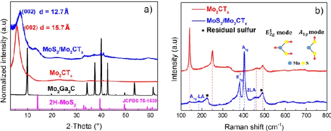
The XRD patterns of Mo2Ga2C, Mo2CTx and MoS2/Mo2CTx are shown in Figure 1a. Also
plotted is the JCPDS file pattern of 2H-MoS2. The diffraction peak, centered at 9.8°,
corresponds to the (002) planes in the Mo2Ga2C phase, 36 is not observed in the diffraction
pattern of Mo2CTx or in the MoS2/Mo2CTx composite, attesting to the complete removal of
the Ga layers. Moreover, and more importantly, the (002) peak of Mo2CTx observed at 5.6° is
downshifted from the corresponding peak centered at 9.8° of the parent phase. This downshift confirms the increase of the interlayer space, d002, as the Ga is replaced by terminal groups (F,
OH, O) 18 and the intercalation of water molecules and TBA+ ions between the sheets after the delamination step. 37 The broadening of the (002) peak, involving a lower crystallinity, is associated with an already reported interstratification phenomenon due to a distribution in the layer-to-layer distances. 38 When a fraction of the MXene flakes react with S, d002 decreases
from 15.7 Å to 12.7 Å. This reduction in spacing is probably the result of a dehydration phenomenon and removal of TBA+ affecting the material during heat treatment. Moreover, an
additional broad diffraction line with low intensity is observed for the sulfurized MoS2/Mo2CTx material at 13.5 °. This peak can be assigned to the most intense peak of the
layered 2H-MoS2 phase.39, 40 The large width of this diffraction peak suggests the formation
of nanostructured coherently diffracting domains of the 2D MoS2 phase. The Raman
spectrum of the MoS2/Mo2CTx material (blue graph in Figure 1b), clearly exhibits bands
centered at 380 and 402 cm-1 corresponding, respectively, to in-plane ( ) mode and an out-of-plane first-order Raman modes of exfoliated few layers MoS2. 41, 42 The
in-plane ( ) mode corresponds to the concerted vibration of S atoms and the Mo atoms in opposite directions while the out-of-plane mode is due to the out-of-plane vibrations of S atoms. 43 The and modes, bands around 187 and 452 cm-1, are also observed
in the Raman spectrum. The band centered at 187 cm-1 is assigned to combined
Raman mode, where LA stands for a longitudinal acoustic phonon mode. The peak centered around 452 cm-1 is assigned to a second-order phonon peak (2LA) and a first-order mode.12, 41 The most intense peak of Mo2CTx is observed at ca. 140 cm-1 (red curve of Figure
1b). When combined with MoS2 (blue curve in Figure 1b) that peak’s intensity is greatly
attenuated suggesting that this phase was at least partially consumed in the sulfurization reaction. From Figure 1b (blue curve) it can be noted that the intensities of peaks around 225 and 490 cm-1 are higher than the intensity of the most intense peak registered with Mo2CTx
MXene (located at ca. 140 cm-1), thus indicating that another vibration phenomenon is responsible for the additional peaks. We ascribe these peaks to the presence of residual molecular sulfur (S8). This assignment is strongly supported by the experimental spectrum
recorded with the S powder used for the sulfurization process (Figure S1). It is also in agreement with literature data. 44
FIGURE 1
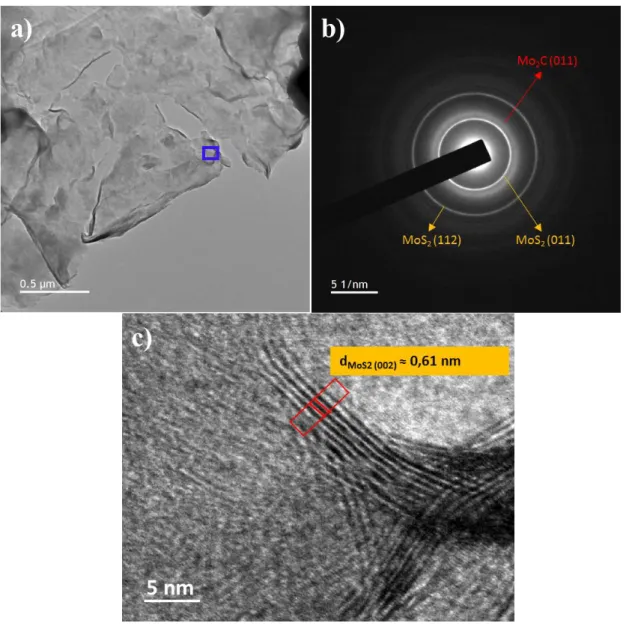
To shed more light on the morphology and distribution of MoS2/Mo2CTx, transmission
electron microscope (TEM) observations were performed. Typical TEM micrograph (Figure 2a) of MoS2/Mo2CTx and the corresponding selected area electron diffraction (SAED) pattern
The three highest intensity diffraction rings (Figure 2b) correspond to the reflections of the (011) planes of MoS2 and Mo2CTx respectively, and to the (112) plane of MoS2. And while
the diffraction rings that relate to MoS2 are sharp, the reflection associated with Mo2CTx are
relatively broad, that is most probably an indication of S doping. The high-resolution TEM micrograph shown in Figure 2c confirms our Raman spectroscopy results, clearly showing several stacked layers of MoS2 on a Mo2CTx sheet.
FIGURE 2
Scanning electron microscope (SEM) images of the initial Mo2CTx, as well as of
MoS2/Mo2CTx heterostructure (Figure S2), clearly show the 2D nature of our materials.34, 45
No significant morphological differences were observed between the two materials, suggesting that the MoS2 flakes superimpose, or cover, the Mo2CTx flakes in accordance with
TEM analyses.
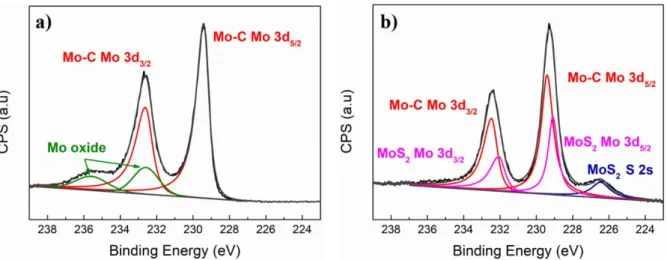
X-ray photoelectron spectroscopy (XPS) was also undertaken to analyze the surface chemistries and compositions of both the Mo2CTx and MoS2/Mo2CTx powders. Using the
procedure outlined by Halim et al. 34, we used the Mo 3d, C 1s, O 1s and F 1s regions (see Figure S3 in supporting information) to estimate the chemical formula of Mo2CTx to be
Mo2CO0.6(OH)0.4(OH-H2O)0.15F0.25 (see Tables S1 and S2 in supporting information). Usually,
using high HF concentrations during etching leads to a high F content as terminal groups in the resulting MXene. 46 In our case, the F content in Mo2CTx is quite low. This is due to the
TBAOH treatment used to delaminate the flakes that, in turn, is known to replace F- by O- or OH terminations. 47 The Mo 3d region of the Mo2CTx materialis shown in Figure 3a. Peaks
ascribed to the Mo-C contribution are respectively centered at ca. 229.4 and 232.6 eV. 34 Peaks centered at ca. 232.5 and 235.5 eV can be assigned to Mo6+ containing species and especially to the presence of MoO3 as an impurity 34 Mo 3d, as well as, S 2s regions for the
MoS2/Mo2CTx material are shown in Figure 3b. FIGURE 3
The Mo 3d experimental signal can be decomposed using four different peaks respectively centered at ca. 229.0, 229.4, 232.2 and 232.6 eV. Whereas the peaks centered at 229.4 and
232.6 eV can be assigned to the MXene, the others can be ascribed to the Mo 3d5/2 and Mo
3d3/2 doublet associated with the presence of Mo4+ containing specie, that are associated with
the formation of MoS2. 34, 39 The presence of MoS2 is more conclusively evidenced from the
decomposition of the S 2p experimental signal region (Figure S4, in supporting information). This peak is undoubtedly due to Mo-S bonds. 39 A characteristic peak of elemental S located at 164.8 eV is also observed confirming the Raman characterization. From this photopeak, the percentages of sulfur atoms contained into MoS2 and molecular sulfur can be extracted.
These values are presented in Table S3. From these values, the MoS2/S molar ratio was
evaluated to be. 1/0.53.The knowledge of this ratio coupled to ICP results (Table S4) allows for the determination of the Mo2CTx/MoS2/S ratio in the composite (see experimental details in
supporting information file – section 4b) which was found to be 1/2.46/1.32, respectively . In contradistinction to Mo2CTx, the Mo 3d region registered with the MoS2/Mo2CTx
heterostructuresdoes not exhibit peaks associated with MoO3. In this case, residual MoO3 is
most probably transformed into MoS2 during the sulfurization process. It is well-known that
S vacancies easily react with oxygen to form MoO3 even after short exposure to air. 48
Consequently, as no MoO3 can be detected after short air exposure, that couldbe considered
as evidence for the absence of S deficiency in the prepared composite.
From the totality of our XRD, SEM, TEM, XPS and Raman spectroscopy results, it is reasonable to conclude that we formed MoS2/Mo2CTx heterostructures composed of MoS2
nanosheets superimposed onto Mo2CTx MXene.
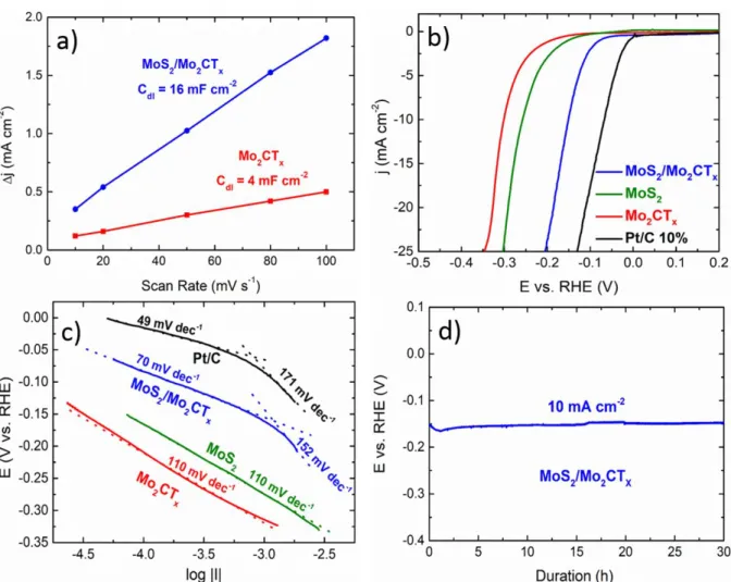
An estimation of the electrochemical surface active area (ECSA) of MoS2/Mo2CTx and
Mo2CTx catalysts can be performed by measuring the electrochemical double-layer
capacitance (Cdl) of the catalysts. The Cdl values can be determined by recording cyclic
voltammogramms in a non-Faradaic potential region at different scan rates. 49 Voltammograms obtained at different scan rates with Mo2CTx and MoS2/Mo2CTx samples are
presented in Figure S5. The ESCA can be then estimated from the ratio of the measured double layer capacitance with respect to the specific capacitance of an atomically smooth material. The latter capacitance was assumed to be ≈ 60 µF cm-250, 51
for the heterostructured catalysts clearly exposing MoS2 nanosheets to the electrolyte as well as for Mo2CTx MXene. 52
heterostructure and only of 4 mF cm-2geo for Mo2CTx. This respectively corresponds to
estimated ECSA values of ca. 19.5 cm2 and 4.7 cm2. These values are obtained for a same mass of catalyst (24 µg) and they correspond to specific surface areas of ca. 81.2 m2 g-1 and 19.6 m2 g-1 respectively. This clearly shows that the topotactic sulfurization process probably leads to an increase in the ECSA value by creating defects or by favoring sheets delamination.
The catalytic performance of MoS2/Mo2CTx toward HER was then evaluated by recording
linear sweep voltammograms (LSV) in a nitrogen-saturated 1 mol L-1 KOH electrolyte at a scan rate of 5 mV s-1, using a disk electrode rotating at 1600 rpm (Figure 4b). The electrocatalytic activities of Mo2CTx, commercial Pt/C catalyst (10 wt. % Pt on carbon black
E-TEK), were also tested under identical experimental conditions for comparison (Figure 4b). The catalytic activity of MoS2, determined in the work of Anjum et al. 35, is also plotted on
this figure for comparison’s sake. Clearly, the onset potential for the heterostructured catalyst is only 50 mV more negative than for the benchmark Pt/C catalyst. This value is notably lower than for Mo2CTx or MoS2. Since Mo2CTx is used as starting material for the synthesis
of MoS2/Mo2CTx and as ECSA (for a same catalyst mass loading) of MoS2/Mo2CTx is higher
than for Mo2CTx, it is plausible that the heterostructure contains more undercoordinated sites.
In alkaline medium, the proton source is water and the HER mechanism is quite different than in acidic environment. The major role played by adsorbed hydroxyl on HER kinetics has already been underlined. 53 Adsorbed hydroxyl does not interfere in the reaction mechanism but its presence allows decreasing the water dissociation barrier. 53 In our case, the presence of low coordinated sited reinforces the ability of the surface to stabilize the Σ-OHad-H2Oad
complex54 (where Σ is the active site) thus favoring water activation at low overpotentials. Moreover, the interaction between MoS2 sheets and the underlying Mo2CTx phase strongly
affects hydrogen binding energy. This is supported by literature data since it was demonstrated that MoS2/Mo2CO2 contacts are not Schottky in nature but rather Ohmic. 55
This allows good electrical contact between the MoS2 and MXene basal planes and also
modify the H adsorption energy. 55 The latter is made possible thanks to a facilitated charge injection into MoS2.55
were plotted (Figure S6). From curves presented in Figure S6, it is clear that intrinsic HER activity of our composite is higher than for MoS2 or Mo2CTX explaining that activity
differences cannot be solely explained by ECSA effect. Furthermore, conductivities obtained with the different powders (MoS2, Mo2CTx, MoS2/Mo2CTx) are presented in Table S5. As can
be observed from Table S5, the difference of electrical conductivity between MoS2 and
MoS2/Mo2CTx is not significant, while the electrical conductivity of Mo2CTx is slightly higher
than the two other samples (but still the same order of magnitude). Therefore, we cannot attribute the performance enhancement by an improved electrical conductivity.
Further, even our composite contains molecular sulfur (S8), this latter is not known to be an
efficient HER catalyst so that, the presence of residual molecular S cannot be considered to be responsible for improving the HER activity.
Additionally, the overpotential required to drive a current density of 10 mA cm-2geo (Ej(10))
with the MoS2/Mo2CTx catalyst is of ca. 0.15 V. This value is lower than either Mo2CTx or
MoS2 alone, where the overpotentials are 0.3 V and 0.25 V, respectively. These performances
are higher than those reported for other MoS2-based heterostructures studied on glassy carbon
substrates (Table S6). Only materials deposited onto 3D substrate such as carbon cloth and Ni foam, that promotes mass transfer and the Ni effect, respectively, perform better (Table S6). Figure 4c shows Tafel plots determined from the IR-corrected polarization curves presented in Figure 4b. For MoS2/Mo2CTx and Pt/C catalysts, two different Tafel slopes can be observed:
one at low overpotentials and one at high overpotentials. For Mo2CTx and MoS2, only one Tafel
slope can be clearly identified. Conformly to what is reported 56 only Tafel slope obtained at high overpotentials can be considered as significant. Values obtained could be in favor of Volmer Heyrovsky mechanism in agreement with ref. 57
Lastly, the electrochemical stability under working conditions is another key parameter. For this purpose, a current density of 10 mA cm-2 was applied for up to 30 h in a 1 mol L-1 KOH electrolyte. The results are shown in Figure 4d. As can be observed the electrode potential did not significantly vary during the test, signifying the high stability of our structure towards HER in alkaline media.
As shown in Figure S7, the catalytic activity of an aged Mo2CTx material drastically
performances of an aged MoS2/Mo2CTx heterostructure is quite stable under the same storage
conditions. This result is of upmost importance since it is known that MXenes can be quite oxidation sensitive, the oxidation of which leads to dramatic modifications of their surface properties and a decrease in their electronic conductivity. 31 Such modifications obviously strongly impact their catalytic performances towards HER. Fortuitously, herein the presence of MoS2 seems to inhibit the oxidation process at the surface and/or more likely at MXene
edges. Additionally, the drying procedure adopted here partly removes some of the intercalated water which may play a role in MXene oxidation. Maintaining the MXene properties is of upmost importance for any commercial application and the fact that the heterostructures help in retaining the catalytic properties is an added important bonus. 20
FIGURE 4
Conclusions
To summarize, a novel 2D heterostructured HER catalyst comprised of MoS2 nanosheets
strongly interacting with Mo2CTx MXene flakes was synthesized by the topotactic and partial
sulfurization of Mo2CTx. The as-synthesized heterostructure demonstrates a high
electrocatalytic activity towards alkaline HER. The intrinsic activity is higher than that of MoS2 or Mo2CTx separately. The synthesized heterostructured catalyst also demonstrated
remarkable stability under working conditions for 30 h. This high activity most probably results from an improved interfacial charge transfer between MoS2 and Mo2CTx phases
notably allowing for modifying the adsorption energy of H. Moreover the ability of this catalyst to operate at low overpotentials is due to the lowering of the water dissociation barrier in reason of a stabilization of the water activated complex. These comments notwithstanding, it is hereby acknowledged that much more work – especially theoretical calculations – is needed to further support our conclusions. Additionally, the full understanding of the morphology, interfacial composition, and interaction between both phases also requires further investigations.
In this work, we demonstrate, for the first time, that a simple, inexpensive, scalable synthesis pathway could lead to the emergence of a new class of 2D heterostructured catalysts resulting
from the topotactic modification of MXene that could be useful for electrocatalytic applications in alkaline and other media. Taking into account the very large compositional space afforded by the MXene family, we hope this work swill lead to the synthesis of many other new and highly efficient sulfide or other MXene heterostructures for a wide range of applications.
Acknowledgments
The authors acknowledge financial support from the “Agence National de la Recherche” (reference ANR-18-CE08-014 – MXENECAT project), the European Union (ERDF), the "Région Nouvelle Aquitaine" and the French research ministry (Ph.D. thesis of M. Benchakar). The authors gratefully acknowledge also l’École Doctorale Théodore Monod, Drexel University and Foundation of the University of Poitiers for their financial support for the short-term stay of Mohamed BENCHAKAR in the Department of Materials Science and Engineering, Drexel University, Philadelphia, USA. MWB and VN were supported by the National Science Foundation (DMR-1740795). Lastly, the authors thank Nadia Guignard for her assistance on Raman spectroscopy measurements and Saad Intikhab for his help on the electrochemical measurements.
References
1. M. S. Dresselhaus and I. L. Thomas, Nature, 414, 332 (2001).
2. M. G. Walter, E. L. Warren, J. R. McKone, S. W. Boettcher, Q. Mi, E. A. Santori and N. S. Lewis, Chem. Rev., 110, 6446 (2010).
3. F. Yu, H. Zhou, Y. Huang, J. Sun, F. Qin, J. Bao, W. A. Goddard, S. Chen and Z. Ren, Nat.
Commun., 9, 2551 (2018).
4. B. Hinnemann, P. G. Moses, J. Bonde, K. P. Jørgensen, J. H. Nielsen, S. Horch, I. Chorkendorff and J. K. Nørskov, J. Am. Chem. Soc., 127, 5308 (2005).
5. J. Bonde, P. G. Moses, T. F. Jaramillo, J. K. Nørskov and I. Chorkendorff, Faraday
Discuss., 140, 219 (2009).
6. Z. Zhang, W. Li, M. F. Yuen, T.-W. Ng, Y. Tang, C.-S. Lee, X. Chen and W. Zhang, Nano
Energ., 18, 196 (2015).
7. Q. H. Wang, K. Kalantar-Zadeh, A. Kis, J. N. Coleman and M. S. Strano, Nat.
Nanotechnol., 7, 699 (2012).
8. P. Thangasamy, S. Oh, S. Nam and I.-K. Oh, Carbon, 158, 216 (2020).
(2017).
10. N. H. Attanayake, S. C. Abeyweera, A. C. Thenuwara, B. Anasori, Y. Gogotsi, Y. Sun and D. R. Strongin, J. Mater. Chem. A, 6, 16882 (2018).
11. J. Wei, M. Zhou, A. Long, Y. Xue, H. Liao, C. Wei and Z. J. Xu, Nano-Micro Lett., 10, 75 (2018).
12. J.-Y. Wu, M.-N. Lin, L.-D. Wang and T. Zhang, J. Nanomater., 2014, 852735 (2014). 13. M.-R. Gao, J.-X. Liang, Y.-R. Zheng, Y.-F. Xu, J. Jiang, Q. Gao, J. Li and S.-H. Yu, Nat.
Commun., 6, 5982 (2015).
14. X. Yan, L. Tian, M. He and X. Chen, Nano Lett., 15, 6015 (2015).
15. H. Lin, Z. Shi, S. He, X. Yu, S. Wang, Q. Gao and Y. Tang, Chem. Sci., 7, 3399 (2016). 16. S. Li, C. Cheng, A. Sagaltchik, P. Pachfule, C. Zhao and A. Thomas, Adv. Funct. Mater.,
29, 1807419 (2019).
17. P. Kuang, T. Tong, K. Fan and J. Yu, ACS Catal., 7, 6179 (2017).
18. M. Naguib, O. Mashtalir, J. Carle, V. Presser, J. Lu, L. Hultman, Y. Gogotsi and M. W. Barsoum, ACS Nano, 6, 1322 (2012).
19. M. Alhabeb, K. Maleski, B. Anasori, P. Lelyukh, L. Clark, S. Sin and Y. Gogotsi, Chem.
Mater., 29, 7633 (2017).
20. M. Benchakar, T. Bilyk, C. Garnero, L. Loupias, C. Morais, J. Pacaud, C. Canaff, P. Chartier, S. Morisset, N. Guignard, V. Mauchamp, S. Célérier and A. Habrioux, Adv.
Mater. Int., 6, 1901328 (2019).
21. H. Zou, B. He, P. Kuang, J. Yu and K. Fan, ACS Appl. Mater. Int., 10, 22311 (2018). 22. J. Liu, W. Peng, Y. Li, F. Zhang and X. Fan, Trans. Tianjin University (2020). 23. K. Hantanasirisakul and Y. Gogotsi, Adv. Mater., 30, 1804779 (2018).
24. X. Zhan, C. Si, J. Zhou and Z. Sun, Nanoscale Horiz. (2020).
25. L. Verger, C. Xu, V. Natu, H.-M. Cheng, W. Ren and M. W. Barsoum, Curr. Opin. Solid
State Mater. Sci., 23, 149 (2019).
26. J. Peng, X. Chen, W.-J. Ong, X. Zhao and N. Li, Chem, 5, 18 (2019).
27. J. Ren, H. Zong, Y. Sun, S. Gong, Y. Feng, Z. Wang, L. Hu, K. Yu and Z. Zhu,
CrystEngComm, 22, 1395 (2020).
28. R. Meshkian, L.-Å. Näslund, J. Halim, J. Lu, M. W. Barsoum and J. Rosen, Scripta
Mater., 108, 147 (2015).
29. D. A. Kuznetsov, Z. Chen, P. V. Kumar, A. Tsoukalou, A. Kierzkowska, P. M. Abdala, O. V. Safonova, A. Fedorov and C. R. Müller, J. Am. Chem. Soc., 141, 17809 (2019).
30. Z. W. Seh, K. D. Fredrickson, B. Anasori, J. Kibsgaard, A. L. Strickler, M. R. Lukatskaya, Y. Gogotsi, T. F. Jaramillo and A. Vojvodic, ACS Energ. Lett., 1, 589 (2016).
31. S. Intikhab, V. Natu, J. Li, Y. Li, Q. Tao, J. Rosen, M. W. Barsoum and J. Snyder, J.
Catal., 371, 325 (2019).
32. X. Wu, Z. Wang, M. Yu, L. Xiu and J. Qiu, Adv. Mater., 29, 1607017 (2017).
33. J. Liang, C. Ding, J. Liu, T. Chen, W. Peng, Y. Li, F. Zhang and X. Fan, Nanoscale, 11, 10992 (2019).
34. J. Halim, S. Kota, M. R. Lukatskaya, M. Naguib, M.-Q. Zhao, E. J. Moon, J. Pitock, J. Nanda, S. J. May, Y. Gogotsi and M. W. Barsoum, Adv. Funct. Mater., 26, 3118 (2016). 35. M. A. R. Anjum, H. Y. Jeong, M. H. Lee, H. S. Shin and J. S. Lee, Adv. Mater., 30, 1707105 (2018).
36. C. Hu, C. C. Lai, Q. Tao, J. Lu, J. Halim, L. Sun, J. Zhang, J. Yang, B. Anasori, J. Wang, Y. Sakka, L. Hultman, P. Eklund, J. Rosen and M. W. Barsoum, Chem. Commun., 51, 6560 (2015).
37. O. Mashtalir, M. Naguib, V. N. Mochalin, Y. Dall’Agnese, M. Heon, M. W. Barsoum and Y. Gogotsi, Nat. Commun., 4, 1716 (2013).
38. S. Célérier, S. Hurand, C. Garnero, S. Morisset, M. Benchakar, A. Habrioux, P. Chartier, V. Mauchamp, N. Findling, B. Lanson and E. Ferrage, Chem. Mater., 31, 454 (2019). 39. C. Chen, X. Xie, B. Anasori, A. Sarycheva, T. Makaryan, M. Zhao, P. Urbankowski, L.
Miao, J. Jiang and Y. Gogotsi, Angew. Chem. Int. Ed., 57, 1846 (2018).
40. T. Jia, M. M. J. Li, L. Ye, S. Wiseman, G. Liu, J. Qu, K. Nakagawa and S. C. E. Tsang,
Chem. Commun., 51, 13496 (2015).
41. H. Li, Q. Zhang, C. C. R. Yap, B. K. Tay, T. H. T. Edwin, A. Olivier and D. Baillargeat,
Adv. Funct. Mater., 22, 1385 (2012).
42. C. Lee, H. Yan, L. E. Brus, T. F. Heinz, J. Hone and S. Ryu, ACS Nano, 4, 2695 (2010). 43. A. Molina-Sánchez and L. Wirtz, Phys. Rev. B, 84, 155413 (2011).
44. C. Nims, B. Cron, M. Wetherington, J. Macalady and J. Cosmidis, Sci. Rep., 9, 7971 (2019).
45. L. Li, F. Wang, J. Zhu and W. Wu, Dalton Trans., 46, 14880 (2017).
46. J. Halim, K. M. Cook, M. Naguib, P. Eklund, Y. Gogotsi, J. Rosen and M. W. Barsoum,
Appl. Surf. Sci., 362, 406 (2016).
47. M. Naguib, R. R. Unocic, B. L. Armstrong and J. Nanda, Dalton Trans., 44, 9353 (2015). 48. S. KC, R. C. Longo, R. M. Wallace and K. Cho, J. Appl. Phys., 117, 135301 (2015). 49. G.-Q. Han, Y.-R. Liu, W.-H. Hu, B. Dong, X. Li, X. Shang, Y.-M. Chai, Y.-Q. Liu and
C.-G. Liu, J. Electrochem. Soc., 163, H67 (2016).
50. J. Benson, M. Li, S. Wang, P. Wang and P. Papakonstantinou, ACS Appl. Mater. Int., 7, 14113 (2015).
51. B. Lai, S. C. Singh, J. K. Bindra, C. S. Saraj, A. Shukla, T. P. Yadav, W. Wu, S. A. McGill, N. S. Dalal, A. Srivastava and C. Guo, Mater. Today Chem., 14, 100207 (2019).
52. C. Wu and J. Li, ACS Appl. Mater. Int., 9, 41314 (2017).
53. D. Strmcnik, P. P. Lopes, B. Genorio, V. R. Stamenkovic and N. M. Markovic, Nano
Energy, 29, 29 (2016).
54. P. Farinazzo Bergamo Dias Martins, P. Papa Lopes, E. A. Ticianelli, V. R. Stamenkovic, N. M. Markovic and D. Strmcnik, Electrochem. Commun., 100, 30 (2019).
55. J. You, C. Si, J. Zhou and Z. Sun, J Phys Chem C, 123, 3719 (2019).
56. W. Sheng, H. A. Gasteiger and Y. Shao-Horn, J Electrochem Soc, 157, B1529 (2010). 57. S. Fletcher, J Solid State Electrochem, 13, 537 (2009).
Scheme 1. Schematic illustration of the synthesis, delamination and topotactic sulfurization of
Figure 1. a) XRD patterns of Mo2Ga2C, Mo2CTx, MoS2/Mo2CTx and 2H-MoS2 and, b)
Raman spectra of MoS2/Mo2CTx and Mo2CTx using a 532.4 nm excitation line. The labelled
peaks in bottom spectrum belong to MoS2. Inset on top right show sketches of assigned
Figure 2. a) Typical TEM image of MoS2/Mo2CTx composite. B) Corresponding SAED
patterns taken from the same region. c) Higher magnification of area marked with blue rectangle in (a).
Figure 3. High resolution XPS spectra of Mo3d region for, a) Mo2CTx and, b) MoS2/Mo2CTx
Figure 4. a) Evolution of Δj as a function of scan rate for MoS2/Mo2CTx and Mo2CTx
electrodes. b) Linear sweep voltammograms, at 5 mVs-1, recorded in a nitrogen-saturated 1 mol L-1 KOH electrolyte for MoS2/Mo2CTx, Mo2CTx, MoS2 and Pt/C 10% catalysts using a
rotating disk electrode set at 1600 rpm. The MoS2 results were taken from Ref. 35. c)
Corresponding Tafel plots.d) Chronopotentiometric curves recorded in same electrolyte as (a) at constant current density of 10 mA cm-2 with MoS2/Mo2CTx as catalyst.