HAL Id: hal-02924954
https://hal.archives-ouvertes.fr/hal-02924954
Submitted on 2 Dec 2020HAL is a multi-disciplinary open access archive for the deposit and dissemination of sci-entific research documents, whether they are pub-lished or not. The documents may come from teaching and research institutions in France or abroad, or from public or private research centers.
L’archive ouverte pluridisciplinaire HAL, est destinée au dépôt et à la diffusion de documents scientifiques de niveau recherche, publiés ou non, émanant des établissements d’enseignement et de recherche français ou étrangers, des laboratoires publics ou privés.
Highly active and stable Ni dispersed on mesoporous
CeO2-Al2O3 catalysts for production of syngas by dry
reforming of methane
André L.A. Marinho, Fabio Toniolo, Fabio Noronha, Florence Epron, Daniel
Duprez, Nicolas Bion
To cite this version:
André L.A. Marinho, Fabio Toniolo, Fabio Noronha, Florence Epron, Daniel Duprez, et al.. Highly active and stable Ni dispersed on mesoporous CeO2-Al2O3 catalysts for production of syngas by dry reforming of methane. Applied Catalysis B: Environmental, Elsevier, 2021, 281, pp.119459. �10.1016/j.apcatb.2020.119459�. �hal-02924954�
1
Highly active and stable Ni dispersed on mesoporous
CeO
2-Al
2O
3catalysts for production of syngas by dry
reforming of methane
André L. A. Marinho1,2,3, Fabio S. Toniolo2, Fabio B. Noronha3, Florence Epron1, Daniel
Duprez1, Nicolas Bion1,*
1 Institut de Chimie des Milieux et Matériaux de Poitiers (IC2MP), University of Poitiers,
CNRS UMR 7285, TSA51106 – F86073 Poitiers Cedex 9, France.
2 Federal University of Rio de Janeiro, Chemical Engineering Program of COPPE/UFRJ, P.O.
Box 68502, CEP 21941-972, Rio de Janeiro, RJ, Brazil.
3 National Institute of Technology, Catalysis Division, Rio de Janeiro, RJ 20081-312, Brazil.
2
Abstract
Ni-based mesoporous mixed CeO2-Al2O3 oxide catalysts prepared by one pot Evaporation
Induced Self Assembly (EISA) were tested in dry reforming of methane. The textural, structural and physicochemical properties of the catalysts were studied by N2 adsorption-desorption,
TEM-EDS, XRD and elemental analysis. The mobility of oxygen in the structure and the redox properties were investigated by OSCC measurements, TPR and in situ DRIFTS. Finally, the post-reaction samples were analyzed by TGA, RAMAN and TEM. The calcined catalysts prepared by EISA method present mesoporous structures with highly dispersed Ni in the form of NiAl2O4 spinel clusters. After reduction, small size metallic Ni particles are observed (< 5
nm). The presence of Ce in the structure interacting strongly with Al2O3 promotes the oxygen
mobility and acts as sites for CO2 adsorption, increasing the activity of the catalyst and
promoting the carbon removal mechanism. In absence of Ce in the mesoporous alumina support, the activity for carbon gasification is limited and C filaments accumulate inside the reactor. The same behavior occurs with CeO2-Al2O3 oxide prepared by EISA method when Ni
is post-impregnated because of the presence of isolated larger Ni particles which promotes the decomposition of CH4. Therefore, Ni-based CeO2-Al2O3 catalysts prepared by one pot EISA
method exhibited high activity and stability for the dry reforming of methane thanks to both properties which are the confinement of Ni particles and the inhibition of carbon deposition.
3
1. Introduction
A large number of investigations originated from the necessity to replace the fossil fuel energy by the renewable sources of energy in order to limit the emission of greenhouse gases. Among these sustainable sources of energy, biogas, a first generation biofuel [1] obtained by anaerobic digestion of biomass attracted much attention in recent years. It is composed of CH4,
CO2 and other components like H2S, N2 and H2O [2] in small amounts and can be directly used
as biofuel. Its conversion to high value-added products, like syngas or pure hydrogen by reforming reactions is also of major interest since it consists in the conversion of two greenhouse gases in valuable products. Then, biogas reforming has been extensively studied by many authors in the last years [3–5].
The main industrial process to produce syngas is the steam reforming of methane [6,7]. However, the dry reforming of methane (DRM) appears more interesting when biogas is used as raw bioresource because it does not require the removal of CO2. DRM is a highly
endothermic reaction which occurs above 700 °C and converts CH4 and CO2 to syngas (Eq. 1),
but side reactions occur in the reactor as CH4 decomposition (Eq. 2), reverse Boudouard
reaction (Eq. 3) and reverse water-gas shift reaction (Eq. 4) [2]. CH4 decomposition reaction is
responsible for the carbon formation in the reactor and the RWGS for the decrease of the H2/CO
molar ratio in the syngas.
CH4 + CO2 ↔ 2 CO + 2H2 (1)
CH4 ↔ C + 2H2 (2)
C + CO2 ↔ 2 CO (3)
4
The use of catalysts is required to lower the activation energy for this reaction and the main challenge of this technology is the development of a catalyst resistant to carbon formation. Ni-based catalysts have been studied[8–11] due the low cost and high activity of nickel, but this metal is prone to coke formation by promoting CH4 decomposition. Rostrup-Nielsen et al.[12]
observed that the rate of CH4 decomposition is strongly affected by the Ni particle size and is
favored in large Ni size. Therefore, the limitation of the Ni particle sintering process is crucial to prevent the carbon formation during the DRM at high temperature. The catalyst design enables the control of the metal particle size for instance by embedded the metal particle in the oxide matrix [13] or by generating porosity in which the metal particle can be confined [14].
Mesoporous materials with high surface area and well defined pores have shown interesting results to disperse the metal into the structure. The use of mesoporous oxides like SBA-15 [15], Al2O3 [16] and MCM-41 [15] has been reported to promote high dispersion of
metal. The use of a one-step method to synthetize Ni-based catalysts allows the homogeneous dispersion of Ni with strong metal-support interaction. Evaporation Induced Self-Assembly (EISA) method has been employed by some authors [17–20] to generate very well ordered mesoporous material. Fang et al.[14] prepared Ni-Al2O3 catalysts by EISA method and
observed the formation of the mesoporous structuration in which Ni is highly dispersed due the formation of small NiAl2O4 crystallite. After reduction, Ni metallic particles were smaller than
the ones obtained with impregnated catalysts. It resulted in a decrease of the carbon formation for the Ni-Al2O3 prepared by the one step method.
Besides the control of Ni particle size, the support can also play a key role. A support favoring the presence of oxygen species at the surface of the catalysts may promote the oxidation of the carbon formed on the metal. The oxygen vacancies in the material promote the dissociation of CO2 into CO and O atoms on the surface [21]. The balance between the rate of
5
catalyst [22]. CeO2 presents high oxygen capacity (OSC), which is related to the Ce4+/Ce3+
redox couple associated to the generation of oxygen vacancies. Many researchers [22–24] reported its utilization as a catalyst support to promote the carbon removal mechanism. Fonseca et al.[25] have synthetized CeO2-Al2O3 mesoporous materials by EISA method (with 6 to 35
wt% Ce) and reported the high redox properties of these mixed oxides above 400°C. However, above 20 wt% of Ce the mesoporosity was lost. Wang et al.[26] prepared the NiCeAl catalyst with low Ce/Al ratio by also using EISA method, and studied its catalytic performances in DRM. Catalyst with high surface area and high dispersion of Ni on the support were obtained and a good resistance to carbon deposition was observed at 700°C. The synthesis of mesoporous materials with high substitution of Al by Ce and Ni is more complicated and it is the subject of the present study.
The aim of this study is the preparation of Ni supported on mesoporous CeO2-Al2O3
catalysts by one pot EISA method with high surface area and high Ni dispersion and accessibility for the production of syngas through DRM at high temperature. Two specific parameters have been deeply investigated: the influence of the confinement effect of the one step EISA method compared with the post-impregnation of the Ni; the role of the Ce introduction in the mixed oxide on the carbon gasification properties. N2 physisorption was
performed to study the surface area and porosity. The structure was analyzed by Transmission Electronic Microscopy (TEM) and X-ray diffraction (XRD). In-situ X-ray diffraction (XRD) and Temperature-Programmed Reduction (TPR) were used to follow the reducibility of NiAl2O4. The carbon formed was analyzed by Thermogravimetric analysis (TGA) and TEM.
A brief study was finally carried out by in-situ DRIFTS to investigate the mechanism of carbon removal.
2. Experimental
6
The mesoporous catalysts were prepared using the slightly modified EISA method described by Yuan et al. [27]. 5 g of the surfactant Pluronic 123 (Aldrich) was dissolved in 100 mL of ethanol (99.9 %, Fluka) in a beaker and maintained under stirring for 1 hour. Then, 6 mL of HNO3 (90 wt%, Sigma-Aldrich) was added to the solution, followed by the addition of
aluminum isopropoxide (Aldrich), cerium acetate (Aldrich) and nickel acetate (Aldrich). The solution was maintained under stirring for 5 hours. The evaporation of the solvent was carried out in an oven at 60 °C for 5 days and the samples were calcined in a muffle furnace at 800 °C for 4 hours with a ramp of 1 °C/min. The concentration of metals in the solution was fixed at 0.5 mol/L and a Ce/(Ce + Al) molar ratio equal to 0.1 was used as well as two Ni loadings (5 and 10 wt.%). The amount of Ce corresponds to 20 wt% of CeO2. In addition, one sample
without cerium was prepared according to the same protocol. The prepared samples were denoted as follows: CeAl, 10Ni-Al, 10Ni-CeAl and 5Ni-CeAl.
For comparison, the catalyst denoted as 10Ni/CeAl was prepared by incipient-wetness impregnation of the CeAl support prepared as described above. In this case, the Ni precursor was nickel nitrate (Aldrich) and the impregnation process occurred in ethanol solution. The sample dried in an oven overnight and calcined at 800 °C for 4 hours, 1 °C/min.
2.2 Characterization
The chemical composition of the samples was determined by ICP-OES with a PerkinElmer Optima 2000 DV instrument. The samples were totally mineralized using a mixture of HNO3 and HCl.
The N2 physisorption technique was used to measure the specific surface area and pore
size distribution of each material. The experiment was carried out on TRISTAR 3000 Micromeritics equipment at -196 °C. Approximately 100 mg of catalyst was used for each
7
measurement and the samples were degassed under vacuum overnight at 250 °C. The specific surface was calculated by BET equation and the pore size distribution was calculated by BJH method.
The structure and Ni particle size of the catalyst 10Ni-CeAl was evaluated by Transmission Electron Microscopy (TEM) in a Jeol 2100 UHR apparatus, with 0.19 and 0.14 nm punctual and linear resolution, equipped with a LaB6 filament. The range of X-rays emitted
from the samples upon electron impact was 0-20 keV.
The in situ X-ray diffraction was performed in a Bruker D8 Advance X-ray powder diffractometer operated at 40 kV and 40 mA, using CoKα radiation (λ = 1.790307 Å), equipped with a Position Sensitive Detector, VANTEC-1, kβ filter (Ni), used in scanning mode. The 2θ range analyzed was 10 to 80°, step of 0.05°, step time equal to 2 s. The flow of reduction was composed of 10 % H2/He and the XRD patterns were collected at different temperatures (room
temperature, 200 °C, 600 °C, 800 °C and room temperature after reduction).
Experiments of temperature-programmed reduction (TPR) were performed in a setup equipped with thermal conductivity detector. The samples (400 mg) were pre-treated in-situ under He at 200 °C for 1 hour and cooled down to room temperature. The TPR experiment was carried out from room temperature up to 1000 °C under a 10 % H2/Ar mixture (30 mL/min) and
heating ramp equal to 10 °C/min.
The measurements of Oxygen Storage Complete Capacity (OSCC) were carried out in an atmospheric quartz fixed-bed reactor placed in a furnace connected to a Porapak column and a TCD detector. The method described elsewhere [28] consists in a pretreatment of 20 mg of catalyst under He (30 mL/min) from room temperature to 500 °C, with a ramp of 2 °C/min. At this temperature, the sample is completely oxidized by 10 O2 pulses. After that, 10 pulses of
CO are injected up to the maximum reduction of the sample and a series of O2 pulses to
8
determined from the area of corresponding peaks obtained with the TCD detector. The OSCC values are calculated from the CO2 production instead of CO uptake, due the possibility to form
carbonate species during the CO pulses. The OSCC is expressed in µmol CO2.g-1. The same
procedure was made twice and a mean value of OSCC was retained.
In order to characterize the adsorbed species on the catalysts during the reaction of dry reforming of methane, the technique of Diffuse Reflectance Infrared Spectroscopy (DRIFTS) was performed in-situ. The experiments were carried out in a Bruker Tensor II equipped with a MCT detector and a DRIFTS Harrick environment chamber at 750 °C, which is the maximum temperature reached by the equipment. The experiments consisted in: (i) reduction up to at 750 °C for 1 h, with 10 °C/min heating rate, under 10 % H2/N2 mixture (50 mL/min); (ii) purge of
the chamber with N2 (50 mL/min) at the same temperature for 30 minutes and collection of the
background after the purge; (iii) flow of CH4/N2 mixture (30 mL/min CH4 + 70 mL/min N2)
through the sample for 10 minutes; (iv) flow of CO2/N2 mixture (30 mL/min CO2 + 70 mL/min
N2) through the sample for 10 minutes; (v) flow of CH4/N2 mixture (30 mL/min CH4 + 70
mL/min N2) through the sample for 10 minutes; (vi) flow of CH4/CO2/N2 mixture (30 mL/min
CH4 + 30 mL/min CO2 + 70 mL/min N2) through the sample for 10 minutes. The spectrum was
registered in the range of 1200-4000 cm-1 by collecting 30 scans with a resolution of 4 cm-1. RAMAN spectroscopy was used to characterize the carbon depositions post-reaction (see Supporting Information).
2.3 Catalytic Test
The DRM tests were carried out in a quartz fix-bed reactor at atmospheric pressure. The catalyst was mixed with SiC to ensure a better thermal control in the reactor (SiC/catalyst = 1.5). In order to compare the reaction under similar conversion, the mass of catalyst introduced in
9
the reactor was 20 and 30 mg for 10 wt%Ni and 5 wt%Ni, respectively. The pressure of the reactor was controlled online by a pressure sensor (Keller PR21S, 0-5 bar) to verify the absence of pressure drop. The sample was reduced in situ with pure H2 (30 mL/min) from room
temperature up to 800 °C for 1 hour, with a ramp of 10 °C/min. After the reduction, the reactor was purged with N2 (30 mL/min). The feed composition was 45 mL/min CH4 and 45 mL/min
CO2, without dilution. The outlet gas is analyzed online in 2 analysis zone: the zone 1 consists
in a Varian GC equipped with 3 columns (13X Molecular Sieve, Porapak Q and 5A Molecular Sieve) to separate all the gases, and FID and TCD detectors, using He as carrier gas. In this zone CH4, CO2 and CO are analyzed. The zone 2 concerns the hydrogen analysis in a Varian
GC equipped with 5A Molecular Sieve column, using argon as carrier gas, and a TCD detector. The calculations for the quantification of CH4 conversion (XCH4), CO2 conversion
(XCO2) and H2/CO molar ratio are described in Eq. 5, Eq. 6 and Eq. 7 respectively where Fx is
the molar flow of component x. The molar flow was obtained by an external calibration of each gas, using the total flowrate analyzed online by a flowmeter (Ritter) installed in the outlet gas position. X CH4= (FCH4) in- (FCH4) out (FCH4) in x 100 (5)
X CO2=(FCO2)in- (FCO2) out
(FCO2) in x 100 (6) H2 CO
=
(FH2) out (FCO)out (7)10
After reaction, the reactor was by-passed to conserve the carbon deposits formed during reaction. Differential Thermogravimetric Analysis (DTA) was performed in a TA SDT-Q600 instrument. The variations in the weight of the post-reaction samples (20mg) were monitored increasing the temperature under mixture of 10 % O2/He (100 mL/min) from room temperature
11
3. Results and Discussion
3.1- Catalyst characterization
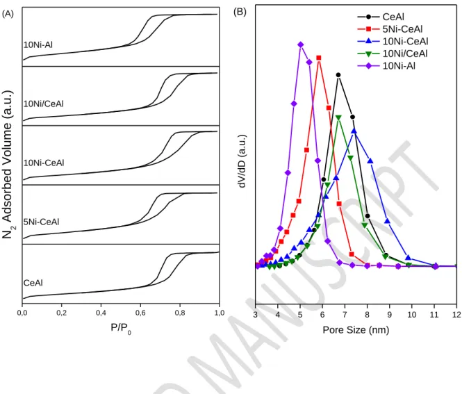
Table 1 reports the chemical composition and textural properties of each sample. The Ni and Ce contents are close to the nominal values. Fig. 1(A) shows the nitrogen adsorption-desorption curves of the samples after calcination. The isotherms are type IV according to the IUPAC classification, characteristic of a mesoporous material, with H1-type hysteresis corresponding to cylindrical pores. Some information on the organization of these pores is given in Fig. 1(B), with narrow distribution of pores for all catalysts. The smallest pore size is obtained for 10Ni-Al sample (distribution between 4 and 6 nm) while the highest pore size and distribution are observed for 10Ni-CeAl (between 4 and 10 nm). The comparison between10Ni-Al and 10Ni/Cebetween10Ni-Al catalysts show that the addition of Ce in the catalyst leads to higher pore size and wider pore distribution. On the contrary, despite of the narrow pore distribution of 10Ni/CeAl, its surface area and pore volume decreased in comparison to CeAl. These result show that the incipient-wetness impregnation of Ni probably causes the blockage of some pores.
The structure of the various samples was characterized by performing XRD and TEM analyses. The XRD at low angle (Fig. S1) does not show any peak characteristic from hexagonal mesoporosity while N2 physisorption isotherms suggested a rather narrow pore size
distribution. Therefore, it seems that the porosity of the material is not well organized, as it can be confirmed by TEM of the calcined 10Ni-CeAl sample (Fig. 2).
12
Table 1: Chemical composition and textural properties of the catalysts.
Sample Ni wt% CeO2 wt% Ce/(Ce+Al) SBET (m2.g -1) Pore Volume (cm3.g-1) Mean Pore Diameter (nm) CeAl --- 21.7 0.10 196 0.47 7.1 5Ni-CeAl 5.1 21.9 0.11 221 0.44 5.8 10Ni-CeAl 9.4 17.5 0.09 208 0.50 7.3 10Ni/CeAl 12.6 18.3 0.10 144 0.35 7.1 10Ni-Al 9.2 --- --- 232 0.42 5.2
13 0,0 0,2 0,4 0,6 0,8 1,0 10Ni-Al 10Ni/CeAl 10Ni-CeAl 5Ni-CeAl P/P0 CeAl N 2 A ds orbed V ol ume (a.u.) (A) 3 4 5 6 7 8 9 10 11 12 d V/ d D (a .u .) Pore Size (nm) CeAl 5Ni-CeAl 10Ni-CeAl 10Ni/CeAl 10Ni-Al (B)
Figure 1: (A) N2 adsorption-desorption curves and (B) distribution of pore size obtained by
14
Figure 2 : TEM images of the calcined 10Ni-CeAl catalyst.
Fig. 3 shows the XRD patterns of (a) Al2O3 and references (Ni/CeO2 and NiAl2O4), (b)
CeAl, 5Ni-CeAl, 10Ni-CeAl, 10Ni/CeAl and 10Ni-Al samples. Al2O3 exhibits peaks at 2 =
38.0°, 44.0°, 53.7° and 80.1°, characteristic of γ phase (JCPDS 00-010-0425). NiAl2O4 phase
(JCPDS 98-006-9509) presents an XRD pattern similar to Al2O3 with peaks at 2 = 37.8°, 44.1°,
53.8° and 79.4°. The diffractograms of CeAl and 5Ni-CeAl samples do not show any peak, corresponding to an amorphous structure. Then, the addition of Ce or 5 wt% Ni into Al2O3
prevents its crystallization during calcination process. On the other hand, the diffractograms of the samples containing 10 wt% Ni show several peaks; 10Ni-CeAl (2 = 43.2°, 53.2° and 78.6°); 10Ni/CeAl (2 = 43.3°, 53.0° and 78.2°); and 10Ni-Al (2 = 43.6°, 53.5° and 79.0°) Although the XRD patterns of NiAl2O4 and γ-Al2O3 are very similar, the position of most
intense lines at high angle characteristic of NiAl2O4 phaseis located at lower 2 value in
comparison to γ-Al2O3 . These results suggest the presence of a significant amount of NiAl2O4
phase for 10Ni-CeAl, 10Ni/CeAl and 10Ni-Al samples. No peaks due to CeO2 phase were
15
that ceria nanoparticles are highly dispersed as nanoclusters on the large alumina surface as observed in our previous work[25].
25 30 35 40 45 50 55 60 65 70 75 80 85 90 In te n si ty (a .u .) 2 (°) Al 2O3 NiAl 2O4 Ni/CeO 2 Al2O3 (a) NiAl2O4 CeO2 25 30 35 40 45 50 55 60 65 70 75 80 85 90 In te n si ty (a .u .) 2 (°) CeAl 5Ni-CeAl 10Ni-CeAl 10Ni/CeAl 10Ni-Al (b) Al2O3 NiAl2O4
Figure 3: Diffractograms of (a) Al2O3 and references (Ni/CeO2 and NiAl2O4), (b) CeAl,
16
In order to investigate the reduction behavior of the samples, in situ XRD was performed during reduction with diluted hydrogen for 5Ni-CeAl, 10Ni-CeAl and 10Ni/CeAl samples (Fig. 4). All the XRD patterns show peaks at 2θ = 51.5° and 75.6° related to Kanthal owned to the equipment. For 5Ni-CeAl, the structure remains completely amorphous from 25 and 600 °C. A peak at 2θ = 62° characteristic of metallic Ni phase (ICSD 98-004-1508) appears at 800 °C. The Ni crystallite size after reduction at 800 °C was 5.4 nm.
For 10Ni-CeAl and 10Ni/CeAl catalysts, the intensity of the lines characteristics of γ-Al2O3 and/or NiAl2O4 decreases and they are shifted to higher 2θ position, when the catalysts
are heated under H2 at 800 °C. Furthermore, it is also observed the appearance of the diffraction
line attributed to metallic Ni at 2 = 62°. These results suggest the reduction of NiAl2O4 phase,
producing metallic Ni and Al2O3. The calculated Ni crystallite size for 10Ni-CeAl catalyst is
4.1 nm. The presence of NiAl2O4 spinel could prevent the sintering of Ni even after reduction
at high temperature. The spinel structure is partially transformed into highly dispersed Ni0 on Al2O3 during reduction. 10Ni/CeAl catalyst has larger Ni crystallite size (11.3 nm) compared
to 10Ni-CeAl, which is a clear effect of the preparation method on the control of the growth of Ni crystallite size at high reduction temperature. However, regardless of the mode of introduction of Ni in the CeAl support prepared by EISA method, NiAl2O4 spinel structure is
formed upon the calcination process at 800°C.
The spinel phase has been commonly used to control the Ni sintering during reduction at high temperature, providing a high metal dispersion on the catalyst[29]. Karam et al.[30] synthetized unsupported NiAl2O4 by EISA method. After reduction at 800 °C, they observed
the formation of Ni0 nanoparticles dispersed over γ-Al
2O3 with very low crystallite size in order
17 20 25 30 35 40 45 50 55 60 65 70 75 80 85 90 In te n si ty (a .u .) 2 (°) 800 °C After 1h 600 °C 200 °C 30 °C 5Ni-CeAl Kanthal Ni 20 25 30 35 40 45 50 55 60 65 70 75 80 85 90 Kanthal Al2O3 Ni In te n si ty (a .u .) 2 (°) 800 °C After 1h 600 °C 200 °C 30 °C 10Ni-CeAl NiAl2O4 20 25 30 35 40 45 50 55 60 65 70 75 80 85 90 CeO2 In te n si ty (a .u .) 2 (°) 10Ni/CeAl NiAl2O4 Al2O3 Ni Kanthal 800 °C After 1h 600 °C 200 °C 30 °C
Figure 4: In situ X-ray diffraction patterns of 5Ni-CeAl, 10Ni-CeAl and 10Ni/CeAl during the
18
The diffractogram of calcined 10Ni/CeAl sample also exhibited the main peak ascribed to CeO2, at 2 = 33.2 (Fig. 4), which is likely due to its segregation after Ni impregnation and
calcination since the CeAl sample did not display this feature (Fig. 3b). However, the intensity of this line starts to decrease when the sample is heated at 200 °C and it is no longer observed after reduction at 800 °C. According to the literature [13,31], the reduction of ceria-based materials leads to the shift of the lines characteristic to CeO2 to lower angles due to the
conversion of Ce4+ to Ce3+ species but the intensities of these lines do not change. Therefore, what is causing the disappearance of the CeO2 lines during reduction?
In order to investigate the ceria reduction behavior, a Ni/CeO2 reference sample was
analyzed by in situ XRD during reduction (Figure S2). It is noticed a shift of the lines corresponding to CeO2 to lower 2θ values, indicating an increase in the ceria lattice parameter
due to the formation of Ce3+ species. In addition, the intensities of these peaks increase as a
result of the growth of ceria crystallite size, However, the lines corresponding to ceria phase are always observed during the reduction process instead of disappearing as it was observed for the 10Ni/CeAl catalyst.
We have previously prepared CexAl samples with different Ce contents (6.0; 11.0; 20.8;
29.3 and 35.3 wt.% Ce) by EISA method [25]. The diffractograms of the calcined samples did not show the lines corresponding to alumina and the lines typical of CeO2 were only detected
for the samples containing 29.3 and 35.3 wt.% Ce. For CexAl containing 6.0; 11.0; 20.8 wt.%
of Ce, the CeO2 lines were only detected when the samples were heated under air at 1000 °C.
This result indicates that CexAl samples prepared by EISA method contain very small and well
dispersed CeO2 nanoclusters. The reduction of the sample with 29.3 wt.% Ce was followed by
in situ XRD. No lines were detected on the diffractograms up to 800 °C but the lines characteristic of CeAlO3 appeared only after heating at 1000 °C. TPR and in situ XANES
19
commercial CeO2 samples exhibited a much lower reduction degree (10%). Based on Isotopic
Exchange and solid-state NMR experiments, it was proposed a reduction mechanism involving the reaction between the ceria nanoclusters and alumina with formation of perovskite-like CeAlO3 (Eq. 8).
2 CeO2 + H2 + Al2O3 2 CeAlO3 + H2O (8)
Luisetto et al.[32] also observed the disappearance of the lines characteristic of CeO2 as
well as the presence of the line attributed to CeAlO3 after reduction at 1073 K of a NiCeAl
sample prepared by the sol-gel method. This result was attributed to the reduction of CeO2 to
Ce2O3, which reacted with alumina to form the CeAlO3 phase (Eqs. 9 and 10). For the sample
prepared by the citric acid method, the diffractograms of the calcined and reduced NiCeAl sample did not exhibit the lines characteristic of CeO2 or CeAlO3 phases. This result was also
observed in our work for 5Ni-CeAl and 10Ni-CeAl catalysts.
2 CeO2 + H2 Ce2O3 + H2O (9)
Ce2O3 + Al2O3 2 CeAlO3 (10)
Chen et al.[33] prepared 10 wt.%Ni/xCeO2/Al2O3 catalysts containing different ceria
content (x = 0, 5, 10, 15 wt.% CeO2) by impregnation of γ- Al2O3 support with a solution of
Ce(NO3)3·6H2O followed by calcination at 450 °C for 2h. Then, the samples were impregnated
with aqueous solution of Ni(NO3)2·6H2O and calcined at 500 °C for 5h. in situ XRD showed
20
corresponding to metallic Ni when the samples were heated at 600 °C. Increasing the reduction temperature continuously decreased the CeO2 lines, whereas the intensities of the metallic Ni
lines increased. At 900 °C, the lines typical of CeO2 completely disappeared and new lines
corresponding to CeAlO3 were detected, indicating that CeO2 was reduced to CeAlO3.
Shyu et al.[34] proposed that small crystallite of CeO2 can be transformed into CeAlO3
at reduction temperatures higher than 600oC, whereas the conversion of large CeO2 particles to
CeAlO3 occurs above 800oC.
In our work, the decrease in the intensity of the line characteristic of CeO2 on the
diffractogram of 10Ni/CeAl catalyst during reduction suggests that Ce3+ species, once they are formed, diffuses into the alumina lattice, forming a CeAlO3 phase that it is not crystalline and,
then it is not detected by XRD. For the other catalysts, CeO2 is highly dispersed over alumina
and then, their lines are not detected on the diffractograms. However, the formation of CeAlO3
is expected for all catalysts prepared by EISA method.
TEM images of reduced 10Ni-CeAl catalyst (Fig. 5) show high number of black spots corresponding to Ni metallic formed after reduction. The Ni particles are homogeneously distributed on the support, with particle sizes around 5 nm, in accordance with values obtained by XRD. The high dispersion of Ni results from the reduction of NiAl2O4, as observed from the
21
Figure 5: TEM images from the structure of the 10Ni-CeAl catalyst after reduction at 800 °C.
The reducibility of the samples was studied by TPR and the profiles are shown in Fig. 6. The sample CeAl presents a broad peak between 400 and 680 °C. According to the literature, Ce-based compounds normally present a first reduction peak at 400 °C, corresponding to the reduction of surface ceria to Ce2O3 while a second peak above 800 °C is attributed to the
reduction of Ce4+ to Ce3+ in the bulk phase [35,36]. In our work, CeAl sample contains only ceria surface species.
22 100 200 300 400 500 600 700 800 900 1000 800 800 860 5Ni-CeAl CeAl 10Ni-Al 10Ni/CeAl 818 T C D Signal ( a. u. ) Temperature (°C) 10Ni-CeAl
Figure 6: TPR profiles of the catalysts and the support CeAl.
The 5Ni-CeAl and 10Ni-CeAl catalysts prepared by the one-pot method show two main reduction peaks; a broad one between 250 and 500 °C and an intense peak with a maximum at around 800°C. The 10Ni/CeAl sample, prepared in two steps, presents the same TPR profile, except that the second reduction peak is shifted to higher temperature, with a maximum at 860°C. For these 3 samples, the first reduction region could be attributed to the surface ceria reduction, as observed for the CeAl sample, or to the reduction of bulk NiO species [21]. However, 10Ni-Al does not present any peak in this temperature range, which suggests the absence of isolated NiO particles in the Ni-based catalysts whatever the mode of incorporation of Ni, in one step (Ni-CeAl) or in two steps (Ni/CeAl), or the composition of the support (CeAl or Al). Therefore, the broad peak between 250 and 500 °C can be mainly attributed to surface ceria reduction. The second peak around 800 °C observed for all Ni-based catalysts is ascribed in the literature to the reduction of NiAl2O4 spinel phase, where Ni is in strong interaction with
23
Ce4+ to Ce3+ and the formation of CeAlO3 perovskite phase above 827 °C in the TPR profile
[32]. However, the support CeAl does not presented this peak at high temperature and we can assume that this peak can be correlated only to NiAl2O4 reduction. The same reduction peak
was observed by Ma et al. [17] in their study about Ni-Al2O3 catalysts prepared by EISA method
and calcined at 700 °C, and it was attributed to the reduction of Ni in spinel structure of alumina. They also confirmed the absence of bulk NiO phase because of the absence of peak at lower temperature in the TPR profile, which was confirmed also by XRD.
It is reported in the literature [38] that the formation of NiAl2O4 in the Ni/Al2O3 catalysts
may occur when the catalyst is calcined above 600 °C, by the reaction between the Ni precursor and the surface Al2O3 oxides. Scheffer et al.[39] studiedthe effect of the calcination temperature
of Ni/Al2O3 catalysts on the Ni phase. The increase of the calcination temperature from 400 °C
to 900 °C shifts the main reduction peak from low temperature, centered at 450 °C, to higher temperature, above 750 °C. The higher calcination temperature favors the diffusion of Ni cations inside the support, making Ni oxide more hardly reducible. Morris et al.[40] observed by using 27Al MAS NMR the replacement of tetrahedrally coordinated Al by Ni, forming NiAl2O4in the samples with 10 wt% of Ni, showing the high solubility of Ni into the Al2O3
framework. They also did not observe the presence of NiO phase in their catalysts. Then, the TPR results of the present study suggest that the EISA method does not favor the formation of bulk NiO species on the support. In contrast the Ni would be incorporated in the Al2O3
framework.
Now, if one compares the TPR profiles of the Ni/CeAl and Ni-CeAl samples to the one of CeAl, it can be seen that the peak ascribed to ceria surface reduction shifts to lower temperature when Ni is present. This supposes that Ni2+ diffused to alumina framework could weaken the interaction between Ce and Al and then ceria can easily reduce in this range of temperature. In order to obtain the reduction degrees of Ce and Ni, the values of H2 consumption
24
and the theoretical values for each reduction are listed on the Table 2. The H2 consumption of
Ce and Ni was calculated assuming at first approximation the reduction of CeO2 to Ce2O3 below
600 °C and NiAl2O4 to Ni0 above 800 °C. The results obtained suggests that CeO2 and NiAl2O4
are not completely reduced during the TPR, with a reduction degree around 50%. Our previous work [25] showed that CexAl materials calcined at low temperature (400 °C), containing CeAlO3 pseudo phase displayed around 100 % of reduction of ceria below 500°C. Therefore,
the calcination at high temperature strengthens the interaction between Ce and Al in the framework, decreasing its reducibility.
Table 2: H2 consumption, theorical consumption and reduction degree for Ce and Ni from the
catalysts. Sample H2 consumption (µmol.g-1) Theoretical H2 consumption (µmol.g-1) Reduction degree (%) Below 600 °C Above 800 °C Ce Ni Ce Ni CeAl 370.0 --- 630.4* --- 59 --- 5Ni-CeAl 359.4 513.2 636.2* 861.3** 56 60 10Ni-CeAl 208.7 931.4 508.4* 1571.6** 41 59 10Ni/CeAl 243.3 1253.4 531.6* 2118.8** 46 59 10Ni-Al --- 837.8 --- 1537.9** --- 54 * 2 CeO2 + H2 Ce2O3 + H2O ** NiAl2O4 + H2 Ni + Al2O3 + H2O
Results of the OSCC measurements, performed to obtain more information about the redox properties of the catalysts, are presented in the Table 3. CO can be oxidized by the O
25
from the CeO2 phase or NiO phase. The oxygen released from CeO2 is of major importance for
the DRM reaction because it can react with the carbon formed during CH4 decomposition,
avoiding the catalyst deactivation by carbon deposition. It should be mentioned that during the OSCC measurements the 10Ni-Al sample does not exhibit any CO2 production. It is explained
by the absence of NiO phase in this sample and the inability of NiAl2O4 phase to directly oxidize
CO at this temperature. The same assumption will be adopted for the samples 5Ni-CeAl and 10Ni-CeAl, considering that all the O atoms are released from CeO2 structure.
Table 3: OSCC at 500 °C for calcined CeAl, 5Ni-CeAl, 10Ni-CeAl and 10Ni/CeAl samples.
Catalyst OSCC (µmol CO2.g-1)
CeAl 273 5Ni-CeAl 348 10Ni-CeAl 309 10Ni/CeAl 323 10Ni-Al 0
The presence of Ce in the structure increases the OSCC value due its reducibility, as observed for the all catalysts as well as for the CeAl support. Furthermore, the addition of Ni in the structure slightly increases the OSCC value. The insertion of Ni into alumina framework led to an increase in the oxygen mobility of oxygen species around Ce atoms, favoring the reduction of Ce4+ to Ce3+. The higher mobility of oxygen in the Ni-based samples prepared by EISA method is in agreement with the shift to lower temperature in the Ce reduction observed during TPR, generating more oxygen vacancies [41]. During the re-oxidation step it was not
26
formed CO2, which is an indication of the low basicity of these samples, characteristic of CeAl
material, as shown in a previous study [25].
3.2- DRM reaction
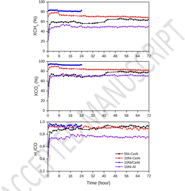
The curves of the CH4 and CO2 conversions and H2/CO molar ratio during the DRM
reaction are presented in Fig. 7. 10Ni-Al and 5Ni-CeAl catalysts exhibited low initial CH4 and
CO2 conversions that significantly increased during the first 2 h of TOS and then they levelled
off. For 10Ni-CeAl and 10Ni/CeAl catalysts, the CH4 and CO2 conversions remained constant
since the beginning of reaction. However, the test was interrupted after 24 h of TOS for 10Ni/CeAl catalyst due to the significant increase in the pressure drop on the reactor. The H2/CO molar ratio after 72 h of TOS was between 0.70 – 0.85 for all catalysts. The H2/CO
molar ratio lower than 1.0 and the conversion of CO2 higher than the conversion of CH4 are due
to the occurrence of the reverse water gas shift reaction (RWGS) (Eq. 4).
The induction period observed for the 10Ni-Al and 5Ni-CeAl catalysts, and to a lesser extent for 10Ni-CeAl, has been reported in the literature for some Ni-basedcatalysts with low basicity [42]. Faria et al.[21] investigated the changes in Ni phase for Ni/Al2O3 catalyst by
XRD. After exposition to a CO2 stream, the diffractogram reveal the appearance of the lines
characteristics of NiO phase and the lines attributed to Ni0 phase are no longer detected. Rabelo-Neto et al.[43] carried out in situ XPS under dry reforming conditions using LaNiO3 precursor
catalyst. They observed a decrease in the intensity of the peak characteristic of metallic Ni at 66.6 eV during the first 120 min of time of stream, which suggests the oxidation of metallic Ni particles. Then, the intensity of this peak increased, indicating that NiO is reduced by the H2
produced in the DRM reaction. These results demonstrated that CO2 can oxidize the surface of
Ni particles when the catalysts are initially contacted with the feed, resulting in a loss of activity. But the partially oxidized Ni particles were reduced again by the syngas produced during the
27
reaction, increasing the conversion of reactants. In our work, it is also possible to observe the low H2/CO at the beginning of the reaction for these catalysts and its increase together with the
enhancement in CH4 conversion after few minutes of time on stream.
0 8 16 24 32 40 48 56 64 72 0 20 40 60 80 100 0 8 16 24 32 40 48 56 64 72 0 20 40 60 80 100 0 8 16 24 32 40 48 56 64 72 0,2 0,4 0,6 0,8 1,0 XC H 4 (% ) XC O 2 (% ) 5Ni-CeAl 10Ni-CeAl 10Ni/CeAl 10Ni-Al H 2 /C O Time (hour)
Figure 7: CH4 conversion, CO2 conversion and H2/CO molar ratio during the dry reforming
of methane performed for the catalysts.
28
The main drawback on the development of catalysts for the dry reforming of methane is the deactivation by carbon formation. Therefore, it is very important to evaluate the carbon formed after the catalytic test. The mechanism of formation and growth of carbon filaments at the metal surface of Ni-based catalysts is well known [12]. The source of this carbon is methane and its dehydrogenation on the surface of the metallic particle, which is the first step of the DRM mechanism. Carbon might be oxidized by O atoms produced by the CO2 dissociation at
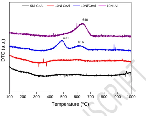
the metal-support interface or it can migrate into the particle structure, leading to the growth of carbon filament. The analysis of the carbon deposited on the samples was made by thermogravimetric analysis after reaction and the corresponding DTG curves are presented in Fig. 8. The 5Ni-CeAl and 10Ni-CeAl catalysts do not present any peak corresponding to the oxidation of carbon species. The 10Ni/CeAl sample displays two peaks centered at 490 and 616 °C while the 10Ni-Al sample has only one centered at 640 °C. According to literature[44,45], the peak at 490 °C ascribed to amorphous carbon structure and the peaks above 600 °C are correlated to filamentous carbon with single or multiple walls (SWCNT and MWCNT). The characterization by RAMAN spectroscopy of the spent catalyst confirms the formation of MWCNT with low degree of crystallinity with bands at 1350 and 1580 cm-1 assigned to D and G bands respectively (Fig. S3) [43]. The rate of carbon formation for the catalysts during DRM at 800 °C for 72 h of TOS are listed on Table 4.
29 100 200 300 400 500 600 700 800 900 1000 490 616 DTG (a .u. ) Temperature (°C)
5Ni-CeAl 10Ni-CeAl 10Ni/CeAl 10Ni-Al
640
Figure 8: DTG curves obtained from the post-reaction samples analyzed by TGA
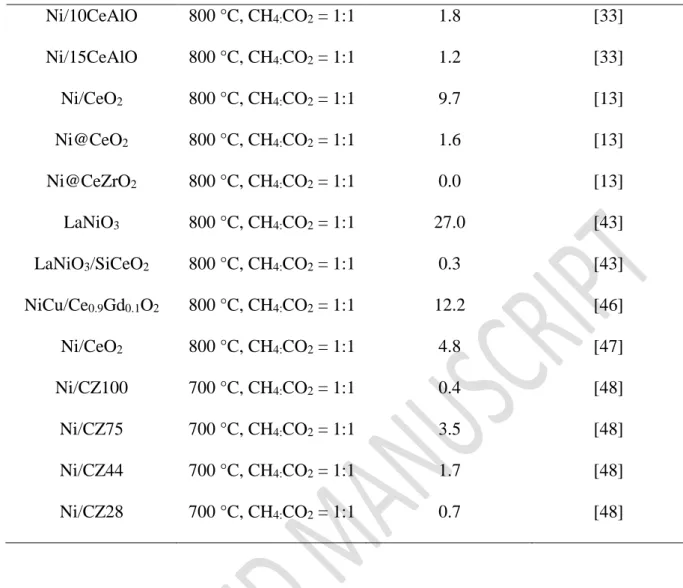
Table 4: Rate of carbon formation on all Ni-CeAl catalysts of this work and data from the
literature after DRM.
Catalyst Reaction Conditions
Rate of carbon deposition (mgC/gcatal/h)
Reference
5Ni-CeAl 800 °C, CH4:CO2 = 1:1 0.0 This work
10Ni-CeAl 800 °C, CH4:CO2 = 1:1 0.0 This work
10Ni/CeAl 800 °C, CH4:CO2 = 1:1 2.0 This work
10Ni-Al 800 °C, CH4:CO2 = 1:1 0.8 This work
Ni/0Ce-AlO 800 °C, CH4:CO2 = 1:1 3.7 [33]
30 Ni/10CeAlO 800 °C, CH4:CO2 = 1:1 1.8 [33] Ni/15CeAlO 800 °C, CH4:CO2 = 1:1 1.2 [33] Ni/CeO2 800 °C, CH4:CO2 = 1:1 9.7 [13] Ni@CeO2 800 °C, CH4:CO2 = 1:1 1.6 [13] Ni@CeZrO2 800 °C, CH4:CO2 = 1:1 0.0 [13] LaNiO3 800 °C, CH4:CO2 = 1:1 27.0 [43] LaNiO3/SiCeO2 800 °C, CH4:CO2 = 1:1 0.3 [43] NiCu/Ce0.9Gd0.1O2 800 °C, CH4:CO2 = 1:1 12.2 [46] Ni/CeO2 800 °C, CH4:CO2 = 1:1 4.8 [47] Ni/CZ100 700 °C, CH4:CO2 = 1:1 0.4 [48] Ni/CZ75 700 °C, CH4:CO2 = 1:1 3.5 [48] Ni/CZ44 700 °C, CH4:CO2 = 1:1 1.7 [48] Ni/CZ28 700 °C, CH4:CO2 = 1:1 0.7 [48]
Fig. 9 shows the TEM images of the post-reaction 10Ni-CeAl, 10Ni-Al and 10Ni/CeAl catalysts. No carbon filaments are observed on the TEM images of 10Ni-CeAl catalyst, in agreement with TG analysis. For this sample, the average Ni particle size is around 10 nm, which indicates a slight increase in comparison to the reduced sample (4-5 nm according to the XRD and TEM results). On the contrary, the images of 10Ni-Al and 10Ni/CeAl catalysts after DRM reaction reveals high carbon formation, with the presence of many carbon filaments. Due to the presence of Ni on the extremity of the carbon filaments (Fig. 9-D and 9-F), these catalysts remained quite active during the reaction until blockage of reactor. The Ni particle size is higher than the ones observed for the 10Ni-CeAl catalyst after three days on stream (around 20 nm for both catalysts).
31
Figure 9: TEM images of the 10Ni-CeAl (A, B), 10Ni-Al (C,D) and 10Ni/CeAl (E, F)
post-reaction catalysts.
3.4- Reaction mechanism for DRM
With the aim of better understand the mechanism of reaction, in-situ DRIFTS experiments were performed under alternatively flowing CH4, CO2, CH4 and CH4/CO2. Fig. 10
displays the spectra collected for 10Ni-Al catalyst obtained after subtraction of the background spectrum. Under CH4 atmosphere, the spectrum presents a very intense band at 3010 cm-1
32
vibration mode of linear CO species adsorbed on metallic Ni [49–51] appears, corresponding to the oxidation of C produced by the decomposition of CH4 with the oxygen coming from the
support. Bands with negative intensities are observed in the 3600-3800 cm-1 region, corresponding to the hydroxyl groups of alumina [52,53]. It means that there was a consumption of hydroxyl groups concomitant with the formation of CO adsorbed on the metal. Ferreira-Aparicio[52] studied the DRM mechanism over Ru/Al2O3 catalysts and they also observed the
participation of OH groups from alumina on the oxidation of carbon formed during the CH4
decomposition. The hydroxyl groups diffuse towards the metal particle promoting the oxidation of carbonaceous species and generating oxygen vacancies on the surface. The steps are demonstrated in the equations 11 – 14.
Switching the gas to CO2, there is the appearance of a very intense band at 2360 cm-1
due to gas-phase CO2. Furthermore, the adsorbed CO is rapidly desorbed and gives gas-phase
CO (double bands centered at 2143 cm-1), which disappears during time on stream while bands at 1573 and 1517 cm-1
, assigned to asymmetric νC=O stretching mode of carbonate species
(CO32-)appears [52]. The 3600-3800 cm-1 region is complicated to analyze due the influence of
some bands attributed to gas-phase CO2, but there is no regeneration of OH group with time,
indicating the difficulty of the support to store O from gas phase and to fill in the oxygen vacancies previously generated. Switching again to CH4, there is CO formation only in gas
phase and the bands in OH region, showing the consumption of carbonates species. The release of oxygen to the metal generates oxygen vacancies on the support, which is occupied by the oxygen from carbonate species. The carbonate species acts as O supply in the absence of CO2.
The participation of this species was also observed by O’Connor et al[54]. Finally, in the presence of the two gases, CH4 and CO2, it is possible to observe CH4, CO2 and CO in gas
phase. It is important to note the absence of carbonate species and the negative bands in OH region under DRM conditions, indicating a surface with deficiency of lattice oxygen species.
33
Then, there is a high consumption of oxygen by carbon gasification in this catalyst and the unbalance between this reaction and the methane decomposition explains the high carbon formation observed for this catalyst. The steps of carbon removal mechanism can be described by the equations (11 to 18). CH4 (g) + 2 * ⇌ CH3* + H* (11) CH3* + * ⇌ CH2* + H* (12) CH2* + * ⇌ CH* + H* (13) CH* + * ⇌ C* + H* (14) C* + OH* ⇌ CO* + VO + H* (15) CO2 (g) + VO + H* ⇌ CO* + OH (16) CO2 (g) + O2- ⇌ 2 CO32- (17) CO32- + VO + H* ⇌ 2 OH- + CO* (18)
34
Figure 10: DRIFTS spectra for 10Ni-Al at 750 °C after; (A) flow of CH4; (B) flow of CO2; (C)
flow of CH4; (D) flow of equimolar CH4/CO2.
Fig.11 shows the spectra of in situ DRIFTS experiment for the 10Ni-CeAl catalyst, which enables the evaluation of the influence of Ce addition. The same adsorbed species observed on the spectra of 10Ni-Al in the presence of CH4 are also detected for 10Ni-CeAl.
However, in the presence of CO2 the bands ascribed to hydroxyl groups with negative
intensities at 3600-3800 cm-1 are no longer observed and the intensity of carbonate bands are higher compared to 10Ni-Al catalyst. Then, the presence of Ce increased the oxygen storage capacity in the material, as observed previously by OSCC. Under DRM condition (Fig. 11-D),
4000 3600 3200 2800 2400 2000 1600 1200 0.0 0.2 0.4 0.6 0.8 1.0 1.2 1.4 3762 3716 10 min Kube lk a-Munk Wavenumber (cm-1 ) 1 min 2060 3670 (A) 4000 3600 3200 2800 2400 2000 1600 1200 0.0 0.5 1.0 1.5 (B) Kube lka-M un k 1517 1573 Wavenumber (cm-1 ) 10 min 1 min 2143 4000 3600 3200 2800 2400 2000 1600 1200 0.0 0.2 0.4 0.6 0.8 1.0 1.2 1.4 (C) 2143 3766 3711 Kube lka-M un k Wavenumber (cm-1 ) 10 min 1 min 3673 4000 3600 3200 2800 2400 2000 1600 1200 0.0 0.5 1.0 1.5 2.0 (D) Ku be lka -Mun k Wavenumber (cm-1 ) 1 min 10 min 2143
35
the bands corresponding to carbonate species are still present, which was not the case for 10Ni-Al. This result indicates that 10Ni-CeAl catalyst has a higher amount of oxygen species on its surface, in the form of CO32- and hydroxyl groups. These carbonate species donate oxygen and
promotes the carbon removal mechanism. Therefore, the correct balance between methane decomposition and carbon gasification explains the absence of carbon deposits during the DRM over 10Ni-CeAl catalyst.
4000 3600 3200 2800 2400 2000 1600 1200 0.000 0.002 0.004 0.006 0.008 0.010 3600 3707 3760 10 min Kube lka-M un k Wavenumber (cm-1 ) 1 min 2053 2143 (A) 4000 3600 3200 2800 2400 2000 1600 1200 0.0 0.1 0.2 0.3 0.4 0.5 (B) Kube lka-M un k 1527 1566 Wavenumber (cm-1 ) 10 min 1 min 2143 4000 3600 3200 2800 2400 2000 1600 1200 0.0 0.1 0.2 (C) 3683 3760 Kube lka-M un k Wavenumber (cm-1 ) 10 min 1 min 2143 4000 3600 3200 2800 2400 2000 1600 1200 0.0 0.1 0.2 0.3 0.4 0.5 (D) (A) 1568 Kubelka-Mun k Wavenumber (cm-1 ) 1 min 10 min 2143
Figure 11: DRIFTS spectra for 10Ni-CeAl at 750 °C after; (A) flow of CH4; (B) flow of CO2;
(C) flow of CH4; (D) flow of equimolar CH4/CO2.
The DRIFTS spectra of the 10Ni/CeAl catalyst in the presence of CH4 do not show the
36
adsorption is lower on large Ni metal particles than on the small ones [55]. Consequently, the CO is more easily desorbed than for catalysts prepared by EISA method due its larger Ni crystallite size, as observed by XRD. Under DRM condition (Fig. 12-D), the catalyst exhibits a spectra very similar to the one observed for 10Ni-Al, with no bands attributed to carbonate species. Then, less oxygen species are available on the surface to promote the carbon oxidation. Therefore, the unbalance between carbon gasification and carbon formation rates is responsible for the high formation of carbon over this catalyst during the catalytic test. The in-situ DRIFTS shows that the addition of Ni and Ce by EISA method improves the amount of oxygen species on the surface of the 10Ni-CeAl catalyst under DRM condition and avoids catalyst deactivation.
4000 3600 3200 2800 2400 2000 1600 1200 0.0 0.2 0.4 0.6 2143 3670 3708 10 min Kube lka-M un k Wavenumber (cm-1 ) 1 min 3762 (A) 4000 3600 3200 2800 2400 2000 1600 1200 0.0 0.5 1.0 Kube lka-M un k 2143 1561 Wavenumber (cm-1 ) 10 min 1 min (B) 4000 3600 3200 2800 2400 2000 1600 1200 0.0 0.2 0.4 0.6 0.8 3700 3762 2143 Kube lka-M un k Wavelength (cm-1 ) 10 min 1 min (C) 4000 3600 3200 2800 2400 2000 1600 1200 0.0 0.5 1.0 1.5 2.0 2.5 3.0 3.5 2143 Ku be lka -Mun k Wavelength (cm-1 ) 1 min 10 min (D)
Figure 12: DRIFTS spectra for 10Ni/CeAl at 750 °C after; (A) flow of CH4; (B) flow of CO2;
37
The mechanism observed in the in-situ DRIFTS experiments is in agreement with the bi-functional mechanism described in the literature by many authors for dry reforming of methane [52,54,56,57]. The CH4 adsorption occurs at the surface of metallic Ni particle,
producing hydrogen atoms and reactive carbon species. The rate of this reaction is extremely affected by the Ni particle size and the formation of carbon species is favored on large Ni particles [58]. The carbon can be oxidized by the oxygen atoms present at the metal-support interface, producing CO. The oxygen vacancy generated is replenished by the oxygen from the CO2 dissociative adsorption, promoting the mechanism of carbon removal from the metallic
surface. Furthermore, CO2 also adsorbs on the basic sites of the support in the form of carbonate
species, which also acts like source of oxygen for the regeneration of oxygen vacancies. However, if the support does not release enough oxygen to the metal particle, the carbon species polymerize to less active carbon, leading to the grow of carbon filaments. Therefore, it is important to have a balance between the rate of methane decomposition on the metal and the rate of carbon gasification at the metal/support interface.
3.5- Effect of control of Ni particle size and oxygen mobility on catalyst stability
The control of Ni particle size plays an important role on the prevention of carbon deposition and catalyst stability during DRM reaction [12,58,59]. Therefore, different catalyst preparation methods have been proposed in the literature to produce small and stable metal particles [26,59–61]. The encapsulated structures, for example core-shell and mesoporous catalysts, have been extensively studied to develop stable catalysts for DRM [62,63]. In this case, the metal is confined into support structure which inhibits metal sintering and suppress carbon deposition. Recently, our group have developed embedded-Ni catalyst in CeO2 and
38
oxygen mobility due to the high interaction between Ni and the support, suppressing carbon formation [13].
The core-shell catalysts have been studied for DRM reaction, however its complexity and the use of high-value added reagents for synthesis methods, has stimulated the search for new synthesis procedures simpler to replicate. Xiang et al.[64] have synthesized NiSiAl samples by EISA method and the catalyst was stable during 100 hours at 700 °C for the DRM reaction with low carbon formation, showing the absence of any sintering process.
In the present work, the Ni particle size effectively affected the carbon deposition rate. The EISA method allowed to synthetize very well dispersed Ni particles on the high surface area support (5Ni-CeAl and 10Ni-CeAl catalysts). The NiAl2O4 spinel phase precursor, as
observed by XRD and TPR, produced small Ni crystallite size during reduction at 800 °C, regardless of the Ni loading, whereas larger particles were formed on the catalysts prepared by the incipient-wetness impregnation method. The smaller Ni crystallite size could control the rate of methane decomposition and avoid carbon formation. However, carbon deposition was still observed on the 10Ni-Al catalyst also prepared by EISA method, which indicates that the presence of ceria is fundamental for catalyst stability [65]. The addition of Ce increases oxygen storage capacity and base properties of the support, leading to an enhanced carbon resistance [66]. In this work, the addition of Ce to prepare the CeAl mixed oxide by EISA method does not contribute to modify the acid-base properties of the support (Fig.S4).
Liang et al. [67] studied the Ni-CeO2-Al2O3 catalyst prepared by EISA method for DRM
reaction. The authors obtained very small Ni nanoparticles over Al2O3 cluster as the support
matrix, obtaining different Ni crystallite sizes according to Ni:Ce:Al proportions. The 10Ni-5Al-1Ce catalyst presented the lowest Ni crystallite size before and after stability test, 5.2 and 12.2 nm, respectively, without catalytic deactivation during DRM reaction. The addition of Ce
39
enhanced catalytic stability, due the better dispersion of Ni and the inhibition of the formation of encapsulated carbon species. The high interaction between Ni-O-Ce prevents further Ni sintering at DRM condition.
Luisetto et al.[32] studied the influence of Ce addition on the performance of Ni/Al2O3
catalyst prepared by different synthesis methods for DRM reaction. The amount of carbon accumulated on the catalysts after DRM at 1073 K decreased from 1000 to 60 mg of carbon/g of catalyst when the Ni crystallite size decreased from 22.6 to 5.8 nm. The catalyst with the highest Ni dispersion exhibited also the highest amount of Ce3+ species determined by XPS. According to the authors, the combination of small Ni crystallite size and high amount of CeAlO3 favored the lower carbon formation on the NiCeAl catalyst during DRM reaction. The
formation of CeAlO3 was also observed by Chein e Fung [68] with the addition of 5wt% of Ce
in Ni/Al2O3 catalyst for DRM reaction. The authors associated the carbon suppression to the
role of CeAlO3 in the catalyst activity, promoting the redox pair Ce4+- Ce3+ during carbon
removal mechanism.
Chen et al.[33] compared the performance of 10 wt.%Ni/xCeO2/Al2O3 catalysts
containing different ceria content (x = 0, 5, 10, 15 wt.% CeO2) for the DRM at 800oC. The rate
of carbon deposition on the catalysts after 250 h of TOS varied from 3,68 mg of carbon/g of catalyst/h (Ni/Al2O3) to 1,16 mg of carbon/g of catalyst/h (Ni/15CeO2/Al2O3). TEM images
revealed that the Ni particle size was approximately the same for all catalysts reduced below 900 oC (at around 10 nm). Therefore, the authors ruled out the effect of Ni dispersion on the formation of carbon. The authors proposed that CeAlO3 formed during reduction reacts with
CO2, producing CeO2 and CO (Eqs. 19 and 20). Prakash et al.[69] also demonstrated the
reversible redox transformation between CeAlO3 and CeO2/Al2O3 oxides at 700 °C and 750 °C
under oxidizing and reducing environments, respectively. The CeAlO3 perovskite-type phase
40
[32]. Then, CeO2 carries out the oxidation of CHx species formed on the metal surface, restoring
and maintaining the redox cycle active.
2 CeAlO3 + CO2 Al2O3 + 2CeO2 + CO (19)
Al2O3 + 2 CeO2 + CHx CO + 2 CeAlO3 + x/2 H2 (20)
Table 4 summarizes the rate of carbon deposition during DRM over different catalysts from the literature. It is clear that the Ni-based catalysts containing ceria prepared by EISA method of our work exhibits lower carbon formation rates than other catalysts from the literature. In the present study, the 10Ni-Al catalyst, which does not have any oxygen mobility in its structure, as shown by the OSCC experiments at 500 °C, is not able to prevent carbon deposition. DRIFTS experiments showed that, at high temperature, the hydroxyl groups can oxidize the carbon formed but the adsorption of CO2 is not favored, decreasing the presence of
oxygen species at the surface and consequently high carbon formation, as showed in TEM images. The presence of CeO2 promotes oxygen mobility in the catalyst, which is responsible
to oxidize the carbon formed on the Ni surface. Therefore, the Ni-based catalysts prepared by EISA method combine the two characteristics necessary for both high activity and resistance to deactivation by carbon formation. Because of the high resistance to coke formation, its application in other reforming process, such as steam reforming of methane, can be interesting in order to maximize the yield for H2 production, with potential to application in pilot plant
41
4. Conclusions
A series of Ni-based catalysts prepared by EISA method was tested in the dry reforming reaction. It was possible to produce materials with high surface area and well defined mesopores. The synthesis conditions favored the formation of NiAl2O4 spinel phase with very
well dispersed Ni particles on the support, which inhibits the sintering process at high temperature. The presence of Ce interacting strongly with Al2O3 promotes the oxygen mobility
in the material, responsible for the carbon removal mechanism, and enhances the activity of the catalyst. The combination of small Ni crystallite and oxygen mobility could suppress carbon formation due the control of the rates of both CH4 decomposition and carbon gasification. These
results indicate that the EISA method is appropriate to produce Ni dispersed catalysts with high surface area and oxygen mobility for application in reforming reactions.
5. Conflicts of interest
The authors do not have any conflicts to declare.
6. Acknowledgements
The authors thank CNPq (Conselho Nacional de Desenvolvimento Científico e Tecnológico, Brazil), CAPES (Coordenação de Aperfeiçoamento de Pessoal de Ensino Superior, Brazil, Finance code 001) and CAPES – COFECUB program (88881.142911/2017-01) for supporting this research and the scholarship received. Stephane Pronier and Nadia Guignard are gratefully acknowledged for TEM and RAMAN experiments respectively. European Union (ERDF) and Région Nouvelle Aquitaine region are also gratefully acknowledged for their financial support.
42
7. References
[1] S.N. Naik, V.V. Goud, P.K. Rout, A.K. Dalai, Production of first and second generation biofuels: A comprehensive review, Renew. Sustain. Energy Rev. 14 (2010) 578–597. [2] L. Yang, X. Ge, C. Wan, F. Yu, Y. Li, Progress and perspectives in converting biogas to
transportation fuels, Renew. Sustain. Energy Rev. 40 (2014) 1133–1152.
[3] N.D. Charisiou, G. Siakavelas, K.N. Papageridis, A. Baklavaridis, L. Tzounis, D.G. Avraam, M.A. Goula, Syngas production via the biogas dry reforming reaction over nickel supported on modified with CeO2 and/or La2O3 alumina catalysts, J. Nat. Gas Sci. Eng.
31 (2016) 164–183.
[4] Y. Kathiraser, Z. Wang, M.L. Ang, L. Mo, Z. Li, U. Oemar, S. Kawi, Highly active and coke resistant Ni/SiO2 catalysts for oxidative reforming of model biogas: Effect of low
ceria loading, J. CO2 Util. 19 (2017) 284–295.
[5] L.F. Bobadilla, V. Garcilaso, M.A. Centeno, J.A. Odriozola, Monitoring the Reaction Mechanism in Model Biogas Reforming by In Situ Transient and Steady-State DRIFTS Measurements, ChemSusChem. 10 (2017) 1193–1201.
[6] A. Boyano, T. Morosuk, A.M. Blanco-Marigorta, G. Tsatsaronis, Conventional and advanced exergoenvironmental analysis of a steam methane reforming reactor for hydrogen production, J. Clean. Prod. 20 (2012) 152–160.
[7] J.R. Rostrup-Nielsen, J. Sehested, J.K. Nørskov, Hydrogen and synthesis gas by steam- and CO2 reforming, in: Adv. Catal., Academic Press, 2002: pp. 65–139.
[8] S. Damyanova, B. Pawelec, K. Arishtirova, J.L.G. Fierro, Ni-based catalysts for reforming of methane with CO2, Int. J. Hydrog. Energy. 37 (2012) 15966–15975.
[9] F. Pompeo, N.N. Nichio, M.M.V.M. Souza, D.V. Cesar, O.A. Ferretti, M. Schmal, Study of Ni and Pt catalysts supported on α-Al2O3 and ZrO2 applied in methane reforming with
CO2, Appl. Catal. Gen. 316 (2007) 175–183.
[10] M. Zhang, J. Zhang, Y. Wu, J. Pan, Q. Zhang, Y. Tan, Y. Han, Insight into the effects of the oxygen species over Ni/ZrO2 catalyst surface on methane reforming with carbon
dioxide, Appl. Catal. B Environ. 244 (2019) 427–437.
[11] D. Li, Y. Nakagawa, K. Tomishige, Methane reforming to synthesis gas over Ni catalysts modified with noble metals, Appl. Catal. Gen. 408 (2011) 1–24.
[12] J. Rostrup-Nielsen, Mechanisms of carbon formation on nickel-containing catalysts, J. Catal. 48 (1977) 155–165.
43
[13] A.L.A. Marinho, R.C. Rabelo-Neto, F. Epron, N. Bion, F.S. Toniolo, F.B. Noronha, Embedded Ni nanoparticles in CeZrO2 as stable catalyst for dry reforming of methane,
Appl. Catal. B Environ. 268 (2020) 118387.
[14] X. Fang, C. Peng, H. Peng, W. Liu, X. Xu, X. Wang, C. Li, W. Zhou, Methane Dry Reforming over Coke-Resistant Mesoporous Ni-Al2O3 Catalysts Prepared by
Evaporation-Induced Self-Assembly Method, ChemCatChem. 7 (2015) 3753–3762. [15] N. Wang, X. Yu, Y. Wang, W. Chu, M. Liu, A comparison study on methane dry
reforming with carbon dioxide over LaNiO3 perovskite catalysts supported on mesoporous
SBA-15, MCM-41 and silica carrier, Spec. Issue Sel. Contrib. 4th Int. Symp. New Catal. Mater. Cancun México August 2011. 212 (2013) 98–107.
[16] Z.-X. Li, F.-B. Shi, L.-L. Li, T. Zhang, C.-H. Yan, A facile route to ordered mesoporous-alumina-supported catalysts, and their catalytic activities for CO oxidation, Phys. Chem. Chem. Phys. PCCP. 13 (2011) 2488–2491.
[17] Q. Ma, L. Guo, Y. Fang, H. Li, J. Zhang, T.-S. Zhao, G. Yang, Y. Yoneyama, N. Tsubaki, Combined methane dry reforming and methane partial oxidization for syngas production over high dispersion Ni based mesoporous catalyst, Fuel Process. Technol. 188 (2019) 98–104.
[18] L. Xu, Z. Miao, H. Song, L. Chou, CO2 reforming of CH4 over rare earth elements
functionalized mesoporous Ni–Ln (Ln = Ce, La, Sm, Pr)–Al–O composite oxides, Int. J. Hydrog. Energy. 39 (2014) 3253–3268.
[19] D. Grosso, F. Cagnol, G.J. de A.A. Soler-Illia, E.L. Crepaldi, H. Amenitsch, A. Brunet-Bruneau, A. Bourgeois, C. Sanchez, Fundamentals of Mesostructuring Through Evaporation-Induced Self-Assembly, Adv. Funct. Mater. 14 (2004) 309–322.
[20] M. Kuemmel, D. Grosso, C. Boissière, B. Smarsly, T. Brezesinski, P.A. Albouy, H. Amenitsch, C. Sanchez, Thermally Stable Nanocrystalline γ-Alumina Layers with Highly Ordered 3D Mesoporosity, Angew. Chem. 117 (2005) 4665–4668.
[21] E.C. Faria, R.C.R. Neto, R.C. Colman, F.B. Noronha, Hydrogen production through CO2
reforming of methane over Ni/CeZrO2/Al2O3 catalysts, Catal. Today 228 (2014) 138-144.
[22] S.M. Stagg-Williams, F.B. Noronha, G. Fendley, D.E. Resasco, CO2 Reforming of CH4
over Pt/ZrO2 Catalysts Promoted with La and Ce Oxides, J. Catal. 194 (2000) 240–249.
[23] A.L.A. Marinho, R.C. Rabelo-Neto, F.B. Noronha, L.V. Mattos, Steam reforming of ethanol over Ni-based catalysts obtained from LaNiO3 and LaNiO3/CeSiO2
44
[24] Z. Liu, D.C. Grinter, P.G. Lustemberg, T.D. Nguyen-Phan, Y. Zhou, S. Luo, I. Waluyo, E.J. Crumlin, D.J. Stacchiola, J. Zhou, J. Carrasco, H.F. Busnengo, M.V. Ganduglia-Pirovano, S.D. Senanayake, J.A. Rodriguez, Dry Reforming of Methane on a Highly-Active Ni-CeO2 Catalyst: Effects of Metal-Support Interactions on C-H Bond Breaking,
Angew Chem Int Ed Engl. 55 (2016) 7455–9.
[25] J. Fonseca, N. Bion, Y.E. Licea, C.M. Morais, M. do C. Rangel, D. Duprez, F. Epron, Unexpected redox behavior of large surface alumina containing highly dispersed ceria nanoclusters, Nanoscale. 11 (2019) 1273–1285.
[26] N. Wang, Z. Xu, J. Deng, K. Shen, X. Yu, W. Qian, W. Chu, F. Wei, One-pot Synthesis of Ordered Mesoporous NiCeAl Oxide Catalysts and a Study of Their Performance in Methane Dry Reforming, ChemCatChem. 6 (2014) 1470–1480.
[27] Q. Yuan, A.-X. Yin, C. Luo, L.-D. Sun, Y.-W. Zhang, W.-T. Duan, H.-C. Liu, C.-H. Yan, Facile Synthesis for Ordered Mesoporous γ-Aluminas with High Thermal Stability, J. Am. Chem. Soc. 130 (2008) 3465–3472.
[28] D. Duprez, C. Descorme, T. Birchem, E. Rohart, Oxygen storage and mobility on model three-way catalysts, Top. Catal. 16/17 (2001) 49–56.
[29] Z. Xu, Y. Li, J. Zhang, L. Chang, R. Zhou, Z. Duan, Bound-state Ni species — a superior form in Ni-based catalyst for CH4/CO2 reforming, Appl. Catal. Gen. 210 (2001) 45–53.
[30] L. Karam, J. Reboul, N. El Hassan, J. Nelayah, P. Massiani, Nanostructured Nickel Aluminate as a Key Intermediate for the Production of Highly Dispersed and Stable Nickel Nanoparticles Supported within Mesoporous Alumina for Dry Reforming of Methane, Mol. Basel Switz. 24 (2019) 4107.
[31] R.O. da Fonseca, G.S. Garrido, R.C. Rabelo-Neto, E.B. Silveira, R.C.C. Simões, L.V. Mattos, F.B. Noronha, Study of the effect of Gd-doping ceria on the performance of Pt/GdCeO2/Al2O3 catalysts for the dry reforming of methane, Catal. Today. (2019).
[32] I. Luisetto, S. Tuti, C. Battocchio, S. Lo Mastro, A. Sodo, Ni/CeO2–Al2O3 catalysts for
the dry reforming of methane: The effect of CeAlO3 content and nickel crystallite size on
catalytic activity and coke resistance, Appl. Catal. Gen. 500 (2015) 12–22.
[33] W. Chen, G. Zhao, Q. Xue, L. Chen, Y. Lu, High carbon-resistance Ni/CeAlO3-Al2O3
catalyst for CH4/CO2 reforming, Appl. Catal. B Environ. 136–137 (2013) 260–268.
[34] J.Z. Shyu, W.H. Weber, H.S. Gandhi, Surface characterization of alumina-supported ceria, J. Phys. Chem. 92 (1988) 4964–4970.
45
[35] G. Lafaye, J. Barbier, D. Duprez, Impact of cerium-based support oxides in catalytic wet air oxidation: Conflicting role of redox and acid–base properties, Catal. Ceria. 253 (2015) 89–98.
[36] H. Yao, Ceria in automotive exhaust catalysts I. Oxygen storage, J. Catal. 86 (1984) 254– 265.
[37] J. Zieliński, Morphology of nickel/alumina catalysts, J. Catal. 76 (1982) 157–163.
[38] R. Molina, G. Poncelet, α-Alumina-Supported Nickel Catalysts Prepared from Nickel Acetylacetonate: A TPR Study, J. Catal. 173 (1998) 257–267.
[39] B. Scheffer, P. Molhoek, J.A. Moulijn, Temperature-programmed reduction of NiOWO3/Al2O3 Hydrodesulphurization catalysts, Appl. Catal. 46 (1989) 11–30.
[40] S.M. Morris, P.F. Fulvio, M. Jaroniec, Ordered Mesoporous Alumina-Supported Metal Oxides, J. Am. Chem. Soc. 130 (2008) 15210–15216.
[41] C.T. Campbell, C.H.F. Peden, Oxygen Vacancies and Catalysis on Ceria Surfaces, Science. 309 (2005) 713.
[42] K. Takanabe, K. Nagaoka, K. Nariai, K. Aika, Influence of reduction temperature on the catalytic behavior of Co/TiO2 catalysts for CH4/CO2 reforming and its relation with titania
bulk crystal structure, J. Catal. 230 (2005) 75–85.
[43] R.C. Rabelo-Neto, H.B.E. Sales, C.V.M. Inocêncio, E. Varga, A. Oszko, A. Erdohelyi, F.B. Noronha, L.V. Mattos, CO2 reforming of methane over supported LaNiO3
perovskite-type oxides, Appl. Catal. B Environ. 221 (2018) 349–361.
[44] M.C. Sánchez-Sánchez, R.M. Navarro, J.L.G. Fierro, Ethanol steam reforming over Ni/MxOy–Al2O3 (M=Ce, La, Zr and Mg) catalysts: Influence of support on the hydrogen
production, EHEC2005. 32 (2007) 1462–1471.
[45] S.M. de Lima, A.M. da Silva, L.O.O. da Costa, J.M. Assaf, G. Jacobs, B.H. Davis, L.V. Mattos, F.B. Noronha, Evaluation of the performance of Ni/La2O3 catalyst prepared from
LaNiO3 perovskite-type oxides for the production of hydrogen through steam reforming
and oxidative steam reforming of ethanol, Appl. Catal. Gen. 377 (2010) 181–190.
[46] G. Bonura, C. Cannilla, F. Frusteri, Ceria–gadolinia supported NiCu catalyst: A suitable system for dry reforming of biogas to feed a solid oxide fuel cell (SOFC), Appl. Catal. B Environ. 121–122 (2012) 135–147.
[47] I. Luisetto, S. Tuti, C. Romano, M. Boaro, E. Di Bartolomeo, Dry reforming of methane over Ni supported on doped CeO2: New insight on the role of dopants for CO2 activation,