Dependency Models as a Basis for Analyzing
Software Product Platform Modularity:
A Case Study in Strategic Software Design Rationalization
by
Matthew J. LaMantia
Submitted to the System Design and Management Program
In Partial Fulfillment of the Requirements for the Degree of
Master of Science in Engineering and Management
at the
MASSACHUSETTS INSTITUTE OF TECHNOLOGY
June, 2006
0 2006 Matthew J. LaMantia All Rights Reserved
MASSACHUSETTS INS 1TUTE
OF TECHNOLOGY
JUN 2
1
2006
LIBRARIES
The author hereby grants to the Massachusetts Institute of Technology permission to reproduce and to
BARKER
distribute publicly paper and electronic copies of this thesis document in whole or in part.Signature of Author
L,
Certified By
David J. McGrath jr. Professor tSanqgement and
Certified By
Matthew J. LaMantia System Design and Management Program June 2006
Professor James M. Utterback Thesis Supervisor Innov) ign an4PTfpjor of Engineering Systems
Patrick Hale Director System Design and Management Program
-2-Abstract
It is broadly accepted among software managers and architects that maintaining the
integrity of software designs is important for the long-term health and viability of
software product platforms. The use of modular, information-hiding architectures is
considered beneficial in this regard, because they enable the addition of new features and
the correction of software defects without widespread changes (Pamas, 1972; Pamas,
1978). Moreover, modular architectures in general add value to system designs by
creating options to improve the system by substituting or performing experiments on
individual modules (Baldwin and Clark, 2000). Recent research has sought to clarify and
to define formally these notions of modularity, and their value in the software domain,
though the use of software dependency models and software design structure matrices.
These models provide a graphic representation of the relationships between the building
blocks of large software systems, which can be used to aid visual understanding of their
structure, and which also form the basis for quantitative metrics for evaluating the degree
of modularity of a software system (MacCormack et al., 2005; Sangal et al., 2005;
Sullivan et al., 2006). The goal of this thesis is to contribute to the development and
validation of formal models of modularity and value, by examining the design evolution
of two similar software systems through the lens of software-dependency-based design
structure matrices. We find that the design structure matrix model demonstrates a form
of information-hiding modularity that allows different rates of experiment in different
software modules, and that also allows substitution of a software module without
substantial change to the rest of the software system. Moreover, the cases demonstrate
that such a substitution scenario can confer distinct strategic advantages to a firm. Based
on these results, we suggest that software managers and architects explore modular
architectures that localize areas of risk -
technical and otherwise
-
in software modules
with well-defined interfaces.
-4-Acknowledgements
I am indebted to many members of the academic community, without whose help it
would have been impossible for me to complete - or even to begin - this thesis.
I wish to thank Professor Carliss Baldwin, Dr. John Rusnak, and Professor Alan
MacCormack of the Harvard Business School, whose paper on the design structure of the
Mozilla web browser initially sparked my interest in this topic. They have been
extremely generous in sharing their time, insights, resources, and especially Dr. Rusnak's
software tools, which made this analysis possible.
At the Massachusetts Institute of Technology, Professor James Utterback, who advised
this thesis, provided invaluable counsel on how to approach the whole endeavor, and
directed me to the people who could help me begin. Those people included Dr. Karim
Lakhani, Stefano Mazzocchi, and Professor Marc Meyer of the Northeastern College of
Business Administration.
I am grateful to my fellow graduate students who helped, inspired, and occasionally
prodded me to complete this thesis, especially David Schiller and Erica Fuchs.
Throughout my time at MIT, my classmates and the administration of the System Design
and Management program have been extremely supportive. Thanks to Pat Hale, Helen
Trimble, Ted Hoppe, and William Foley.
My former colleagues, Charles Morehead and Adam Belmont, provided invaluable
assistance in obtaining data necessary for the execution of this analysis.
Finally, I wish to thank my family and friends for their patience and support: Charles,
Ann, and Elise LaMantia; Steven Allen Hoey; Marilyn Fontenrose; Daniel Lavoie; and
Patrick Lamerson.
-6-Table of Contents
CHAPTER 1: IN TRO DUCTIO N ... 11
SOFTW ARE MODULARITY ... 12
SOFTW ARE DESIGN STRUCTURE M ATRICES ... 13
RESEARCH GOALS... 16
CHAPTER 2: M ETH O DO LO GY ... 19
TW O DISTINCT SERVER IMPLEMENTATIONS ... 19
SOURCE CODE DEPENDENCIES ... 22
DEPENDENCY EXTRACTION ... 23
THE SOFTW ARE D SM MODEL... 25
M ODULARITY M ETRICS... 28
CHANGE METRICS ... 31
TOOLKIT DEVELOPMENT... 31
CHAPTER 3: TOMCAT CASE STUDY: ASYNCHRONOUS DESIGN EVOLUTION... 33
BACKGROUND ... 33
DESIGN STRUCTURE OF THE TOMCAT SERVER ... 34
ASYNCHRONOUS EVOLUTION OF PLATFORM MODULES... 38
M ODULARITY M ETRICS... 38
DISCUSSION... 39
CHAPTER 4: COMPANY 2 CASE STUDY: SPLITTING TO ENABLE SUBSTITUTION... 43
BACKGROUND ... 43
APPLICATION OF THE DEPENDENCY STRUCTURE MODEL TO THIS EXAMPLE ... 45
M ODULARITY METRICS ... 52
DISCUSSION... 53
CHAPTER 5: DISCUSSION AND CONCLUSIONS... 57
AN ARCHITECTURE THAT ENABLES EXPERIMENTATION AND SUBSTITUTION... 57
STRATEGIC VALUE OF MODULARITY IN SOFTWARE DESIGN ... 58
RECOMMENDATIONS ... 61
RISKS OF PURSUING STRATEGIC MODULARITY... 62
FUTURE DIRECTIONS... 67
CONCLUSION ... 69
APPENDIX A: COMPUTATIONAL DETAILS OF THE MODEL... 71
AGGREGATION OF CLASS DEPENDENCIES IN THE PACKAGE HIERARCHY ... 71
HIERARCHICAL TOPOLOGICAL SORTING OF PACKAGE AND CLASS DEPENDENCY GRAPHS ... 73
COMPUTING PROPAGATION COST: ALTERNATIVE ALGORITHMS... 74
APPENDIX B: DEPENDENCY ANALYSIS TOOLKIT CODE... 77
OVERVIEW ... 77
SOURCE CODE... 77
REFERENCES ... 129
-8-Table of Figures
FIGURE 1: A SIMPLE DSM WITH THREE DESIGN PARAMETERS, LABELED A, B, AND C. IN THIS EXAMPLE, A
DEPENDS ON B. B DEPENDS ON A. C ALSO DEPENDS ON A. No MODULES DEPEND ON C. ... 14
FIGURE 2: DSM TRANSFORMATION SHOWING ADDITION OF A DESIGN RULE (COLUMN "DR") WHICH
SPECIFIES AN INTERFACE BETWEEN A AND B, THUS RESOLVING THEIR MUTUAL DEPENDENCY. ... 14
FIGURE 3: EXAMPLE TRANSFORMATION FROM CLASS DEPENDENCIES TO SOFTWARE DSM. ... 25
FIGURE 4: A SOFTWARE DSM, BEFORE (TOP) AND AFTER (BOTTOM) SORTING OF MODULES. THE
DEPENDENCY STRUCTURE IS THE SAME, BUT IN THE LOWER DSM, MARKS ABOVE THE DIAGONAL
DENOTE CYCLIC DEPENDENCIES... 27
FIGURE 5: DSM FOR TOMCAT 3.0, SHOWING TWO INDEPENDENT MODULES. THE DSM IS SORTED TO SHOW M ODU LE H IERA RCHY . ...
34
FIGURE 6: BLOCK DIAGRAM OF THE HIGH-LEVEL MODULAR STRUCTURE OF TOMCAT 3.0... 35 FIGURE 7: THE EXTENDED DESIGN STRUCTURE OF TOMCAT 3.0, SHOWING THE SERVLET API CLASSES ASDESIGN RULES. THE DSM IS SORTED TO SHOW MODULE HIERARCHY... 36 FIGURE 8: THE REVISED BLOCK STRUCTURE OF TOMCAT 3.0. ... 37
FIGURE 9: BLOCK ARCHITECTURAL DIAGRAM OF COMPANY 2'S PRODUCT FAMILY, INCLUDING BOTH
PLATFORM AND APPLICATION COMPONENTS... 44
FIGURE 10: DSM OF SERVER 2, BEFORE SPLITTING. NOTE THAT THE SERVER/FRAMEWORK COMPONENT IS
COMPOSED OF A SINGLE, LARGE MODULE. ... 48
FIGURE 11: DSM OF SERVER 2, AFTER SPLITTING. COMPONENTS UNDER THIRD-PARTY LICENSE HAVE BEEN
SEPARATED INTO A NEW TOP-LEVEL MODULE. ... 49
FIGURE 12: BLOCK DIAGRAM OF THE RESTRUCTURED COMPANY 2 PRODUCT FAMILY, IN WHICH LICENSED
COMPONENTS ARE SEPARATED FROM THE MAIN PRODUCT PLATFORM. ... 50
FIGURE 13: BLOCK DIAGRAM OF THE RESTRUCTURED COMPANY 2 PRODUCT FAMILY, IN WHICH A THIRD-PARTY PRODUCT HAS BEEN SUBSTITUTED FOR LICENSED COMPONENTS PREVIOUSLY CONTAINED IN THE PLA T FO R M . ... 5
1
FIGURE 14: DSM SHOWING THE DESIGN STRUCTURE OF THE COMPANY 2 PRODUCT FAMILY OPERATING WITH
A THIRD-PARTY J2E E SERVER... 52 FIGURE 15: BLOCK DIAGRAM SHOWING PROPAGATION OF CHANGES IN THE J2EE API SPECIFICATION
THROUGH THE COMPANY 2 PRODUCT FAMILY. DARK ARROWS INDICATE THE ROUTE OF PROPAGATION.
MODULES THAT ARE POTENTIALLY AFFECTED ARE COLORED GRAY - WHICH IS ALL OF THEM!... 54 FIGURE 16: BLOCK DIAGRAM OF AN ALTERNATE STRUCTURING OF THE COMPANY 2 PRODUCT FAMILY,
DESIGNED TO CONTAIN THE AFFECTS OF CHANGES IN THE J2EE API SPECIFICATION... 55
FIGURE 17: BLOCK DIAGRAM SHOWING THE AFFECT OF THE ALTERNATE STRUCTURING OF THE COMPANY 2 PRODUCT FAMILY, LIMITING PROPAGATION OF CHANGES IN THE J2EE API SPECIFICATION. DARK
ARROWS INDICATE THE ROUTE OF PROPAGATION. MODULES THAT ARE POTENTIALLY AFFECTED ARE C O LO R ED G R A Y ... 56
FIGURE 18: A CLASS DEPENDENCY GRAPH, IN WHICH THE CLASSES (A, B, C, AND D) ARE DENOTED BY CIRCLES, AND DEPENDENCIES ARE SHOWN BY ARCS. THE CLASSES ARE SHOWN AS THEY ARE
CONTAINED WITHIN THE PACKAGE HIERARCHY. PACKAGES ARE SHOWN BY RECTANGLES, AND THEIR
PARENT-CHILD RELATIONSHIPS ARE SHOWN BY DASHED LINES. ... 72
FIGURE 19: CLASS AND PACKAGE DEPENDENCY GRAPH. THE CLASS DEPENDENCIES (DENOTED BY ARCS BETWEEN CIRCULAR NODES) HAVE BEEN AGGREGATED INTO PACKAGE DEPENDENCIES (DENOTED BY
ARCS BETW EEN RECTANGULAR NODES)... 73
10-Chapter 1: Introduction
Longhorn is late.
At the time of this writing, Windows Vista - the next version of its Microsoft's operating
system that was originally code-named Longhorn - is scheduled to be released in early 2007, more than three years after its initial delivery date in the fourth quarter of 2003 (Fried, 2006; Cnet.com, 2006).
The trade press has popularly attributed these delays to a deepening complexity disaster
resulting from the system's lack of modularity: "With each patch and enhancement, it
became harder to strap new features onto the software, since new code could affect
everything else in unpredictable ways" (Guth, 2005). Similarly, Michael Cusumano has
called Vista a "60-m-lines-of-code mess of spaghetti" (quoted by Waters, 2005).
Microsoft Windows is not a single product. It is available in configurations for home
use, professional use, media applications, and servers. It is a product family, and at its
core is a software product platform. Windows happens to be an operating system, but a
software product platform is not necessarily an operating system. Rather, it is the
software component, or set of components, that forms the basis for the architecture and
functionality of a software product family (Meyer and Selinger, 1998).
The story of the Windows delays highlights the ways in which a lack of platform
modularity can have grievous consequences for product families. Conversely, authors
such as Meyer and Webb (2005) have documented how a modular architecture can
-facilitate platform renewal, and the continued health of software product platforms and the product families that rely upon them.
Software modularity
Parnas (1972) introduced the fundamental concepts which define software modularity.
He proposes the principle of "information hiding" as the basis for decomposing software
into modules. He notes that modular decomposition is a design decision, which must be
completed before work can begin on actual implementation. The modular design defines
an implicit division of labor (or at least a divisibility of labor): "a 'module' is considered
to be a responsibility assignment rather than a subprogram."
Modalities of decomposition should be judged by their ability to accrue the benefits of
modular design, which include allowing separate people or groups to work on
components, thus minimizing development time; increasing flexibility by allowing a
single module to be modified without worrying about the whole program; and making
programs easier to design and understand, because a each module may be examined and
understood apart from the others.
In addition, Parnas (1978) argues that the structural design of software determines its
ability to be changed. He introduces the notion of program hierarchy, which establishes a
partial ordering among modules according to a 'uses' relationship. In this paradigm, the process of changing software by expanding or contracting it can be viewed as creating additional families of software modules that are supersets or subsets of the initial family, or as substituting some modules in the family. The critical role of the quality of the
-initial decomposition in making this possible highlights the need to anticipate potential
changes during the planning process.
Software Design Structure Matrices
Although Parnas' notions of modularity are broadly accepted as principles of good
software architecture, they have largely been used as informal guidelines which guide
software architects' intuitions. The application of Design Structure Matrices to software
is an effort to create a formal model as a basis for analyzing software structure, and for
quantifying the value created by these structures.
The Design Structure Matrix (DSM) was initially conceived by Steward (1981) as means
of understanding interactions between design parameters of engineered systems.
Eppinger et al. (1994) extended this model to capture more deeply the correspondence
between design structure and task structure in product development.
A design parameter, in this context, is essentially a subproblem or task of a design, which
must be solved in the final detailed design. A DSM is a square matrix, in which each
design parameter corresponds both to a row and a column of the matrix. Squares in the
matrix have a binary value, either checked or empty. A square is checked if and only if
the task corresponding to its row depends on the task corresponding to the column.
-Figure 1 shows a simple DSM with three tasks.
A B C A
BX
Figure 1: A simple DSM with three design parameters, labeled A, B, and C. In this example, A depends on B. B depends on A. C also depends on A. No modules depend on C.
Baldwin and Clark (2000) integrate DSMs, Parnas' notion of information-hiding
modularity, and the notion of real options from finance theory, to create a general
framework for value in modular product design. They propose that modular architectures
create value by creating options that allow the designer to choose, at a later date, to
change or improve submodules without redesigning the whole system.
Baldwin and Clark also propose the notion of design rules as a means of resolving
interdependencies to create modular architectures. Design rules specify the interface
between modules, and appear at the left-hand side of the DSM. Figure 2 demonstrates
the refactoring of the sample DSM to resolve a cyclical dependency.
DR A B C
A X
LB X I X Ig I B
X
XFigure 2: DSM transformation showing addition of a design rule (column "DR") which specifies an interface between A and B, thus resolving their mutual dependency.
- 14
-A B C
They propose a collection of six "modular operators," which together form a complete set
of design structure transformations. Two of these will be of particular import to this
thesis: Splitting is the act of separating one module into two. Substitution is the act of exchanging an existing module for a new module with advantageous properties, such as
higher performance or lower cost.
Based on this foundation, several authors have recently applied the concept of design
structures to software. Sullivan et al. (2001) apply DSMs to the same classic software
design problem that was originally used by Parnas to illustrate the concept of
information-hiding modularity, demonstrating how this framework can both formalize
and visualize Parnas' concept in the software domain. They also offer an extension to the
DSM model, the environment and design structure matrix (EDSM), in which external entities on which the design parameters depend, such as the computer operating system or
the nature of user interaction, are explicitly added at the left-hand side of the matrix.
Sullivan et al. further demonstrate that the modular decomposition creates option value.
They simulate the results of experiments which refine the value of individual modules
within two architectures which address the same software problem. The architecture
based on the principle of information-hiding modularity shows a greater increase in
overall technical performance, and thus system value. This demonstration is thus a
preliminary validation of Baldwin and Clark's real options model in the software domain.
However, the authors note that the problem is a self-contained example, "divorced from
real markets."
-Sangal et al. (2005) illustrate the use of software DSMs as a means of discovering and
communicating software architecture. They propose that software dependencies may be
used to manage the architectural integrity of software in ongoing development, though
the definition and enforcement of rules constraining dependency relationships of software
modules. They further illustrate this approach through the use of a commercial software
DSM tool to analyze two medium-sized open source projects.
Rusnak (2005) and MacCormack et al. (2005) have studied the relationship between
software architecture and team structure. MacCormack et al. apply the DSM model as a
means of comparing two complex software systems, the Linux kernel and the Mozilla
web browser. They define several metrics based on this model for comparing the degree
of modularity of design structures. This thesis follows closely upon their methods, which
will be discussed in detail in later chapters.
Research goals
The research goal of this thesis is to contribute to the development and validation of
formal models of modularity and value, by examining two case studies of real-world
software systems through the lens of software-dependency-based Design Structure
Matrices. Does the model speak to the value-creating processes in the evolution of these
software systems? What extensions or refinements to the model are suggested by the
cases? Finally, what insights does the model offer for software managers and architects?
This thesis begins, in Chapter Two, with a detailed description of the model and
associated methods. Chapters Three and Four present the two studies, which apply the
model to two similar software systems, one open source and one proprietary. Chapter
16-Five presents a discussion of the results of the case studies, the model itself, and their
implications for software managers and architects.
Two appendices are attached. The first presents some computational and algorithmic
details of the model and its implementation, and the second presents the source code
developed in support of this investigation.
18-Chapter 2: Methodology
Two distinct server implementations
This thesis will examine two software systems, both written in the Java programming
language. The first of these systems is Tomcat, an open source web application server
from the Apache Software Foundation. The second of these systems is a proprietary
application server, which has been analyzed for this thesis with the permission of the
company that develops and sells it. In the interest of protecting the company's strategic
interests, it will remain anonymous. We will refer to this company as "Company 2," and
to its software system as "Server 2."
In the interest of full disclosure, it must be stated that the author of this thesis was
previously employed by Company 2 and has performed firsthand some of the
restructuring of Server 2 that is described in this thesis. The system was chosen as a case
for examination because it was known to illustrate an example of the use of dependency
information to address a strategic problem in a commercial software company.
The Tomcat server was chosen because it is an open-source software system that, like
Server 2, functions as a web application server. Because it is open source, it is available
for analysis without any special access or permission. In addition, MacCormack et al.
(2005) have conjectured that software projects with highly distributed collaboration may
require modular architectures.
-The J2EE Standard
The systems examined in this chapter are web application servers, which implement all or part of the Java 2 Enterprise Edition (J2EE) specification. J2EE is a standard suite of technologies for creating dynamic web-based applications. It is an open standard, to the
extent that it is defined though the Java Community Process (JCP), in which groups of industry experts discuss and define the specification standards. However, the intellectual
property associated with the specification, including the application programming
interfaces and the J2EE brand, is owned by Sun, and licensed to the groups which implement it in their software products (Byous, 2003).
The J2EE suite includes technologies for creating large-scale software applications, using Java technology. It includes technologies for presenting data and user interfaces within a web browser, and for many services which support such applications. In order for an application server product to receive the J2EE brand, the product must fully pass the
J2EE Compatibility Test Suite, consisting of several thousand separate test scenarios,
which verify that the software system complies with the behavior described in the specification (Sun Microsystems, 2003).
The J2EE standard is defined both by textual specifications and by the J2EE Application Programming Interface classes (J2EE API). The integration of the J2EE API as a software component in compliant servers facilitates the interoperability of compliant servers.
There are several distinct implementations of the J2EE specification in existence: At the time of this writing, the Sun website lists 23 for J2EE version 1.3, and 12 for J2EE
-version 1.4 (Sun Microsystems, 2006a; Sun Microsystems, 2006b). Some of these
projects are open-source software.
Because the systems have at least some nominally identical behavior, they provide a way
to compare design structures while minimizing the effect of problem domain on the
design. However, this congruency is highly imperfect. While J2EE servers all
implement the same basic functionality, they also offer additional functionality, not
required or described by the J2EE specification, to add value and differentiate themselves
from competing products. Such functionality might include administrative and
management services; security mechanisms; support for running multiple servers in
tandem on separate machines in a "server farm;" and functionality which acts as a
framework or product platform for vertical applications built on the server platform.
It must also be stated that Server 2 is a much larger software system than Tomcat, by
almost an order of magnitude. Whereas Tomcat only implements a portion of the J2EE
specification, Server 2 implements the entire specification. Server 2 also includes many
application "framework" components, which serve as a platform for Company 2's entire
product family.
Versions of the software examined
All of the software versions examined in this investigation were production releases of the software, and are therefore known to be stably functioning versions of the software.
-Source code dependencies
This thesis will examine these two software systems using a DSM model based on their
source code dependencies. Before describing this model in detail, it is important define
the dependency relationship, and how the data is obtained.
The basic notion of software dependency was defined by Parnas (1978) as a "uses"
relationship. A software module A or entity uses, or depends on, B just in case A
"requires the presence of a correct version of' B.
In practice, there are two kinds of software dependencies: Static, or "compile-time,"
dependencies and dynamic, or "run-time," dependencies.
Static dependencies capture the notion that one software module is necessary in order to
compile another. In other words, A depends on B just in case the source code of A makes
an explicit reference to B. In such a case, in order to compile A to an executable form, it
is necessary to have access to B.
Run-time dependencies, in contrast, are based on actual calling patterns of the software
during operation, and vary according its use and deployment. They cannot, in general, be
inferred from any a priori examination of the software code. For this reason, this
investigation focuses on analyzing static software dependencies.
-Dependency extraction
Tools used
For the Java-based software projects examined in this thesis, an open-source tool, Dependency Finder1, written by Jean Tessier, was used to extract code dependencies. In
Java, it is possible to extract dependencies from the executable, packaged product, so it is
not necessary to have access to source code in order to get the necessary data. This was
an important factor in gaining access to data about the proprietary server product
examined in this investigation.
Unit of analysis
In Java, all software functions and code are encapsulated within classes. A class is a
basic unit of code which corresponds to an entity or unit of software functionality within
the software system.
For this reason, the basic unit of analysis for this investigation is the Java class. This is
roughly, but not exactly, equivalent to the use of the source code file as the basic unit of
analysis by MacCormack et al.2 Typically, one Java class is defined in each source code
file. However, it is possible, on occasion, to define an "inner" class, which appears inside
another Java class. In such cases, two or more Java classes may be defined in the same
source file.
1
Tessier, Jean. Dependency Finder. 4 April, 2006. <http://depfind.sourceforge.net>.2 Unlike Java, in C++, not all functions are encapsulated within classes; it is possible to organize functions
simply by containing them in files. For this reason, the author proposes that classes and files are appropriate and correspondent units of analysis for Java and C++, respectively.
-For the purpose of this investigation, all of the dependency data available from the Java
class files were used. In Java, there are several kinds of class-to-class compile-time dependencies:
* If class A is a subclass of B, then A depends on B. The parent class is necessary to compile its children.
* If any portion of class A makes explicit reference to B as a variable, then it also depends on B.
" If a function in class A calls or makes reference to a function or data member of
class B, then A depends on B.
We assign a strength to the dependency from A to B, equal to the number of unique references, like those described above, from A to B.
Java classes are grouped together into "packages." A Java package is a collection of classes which together implement a larger unit of related functionality. The packages are named hierarchically, with each portion of the package name progressively narrowing the scope of the code contained in it. For example, software from the Apache Foundation is
contained within other packages starting with "org.apache," and the core functionality of version 3.0 of the Apache Tomcat server is contained in the subpackage
"org.apache.tomcat."
These class-to-class dependencies are then aggregated hierarchically into package-to-package dependencies. This information is useful for implementing algorithms to simplify and summarize software DSMs. Details about how this was performed are deferred to Appendix A.
-The Software DSM model
From class dependencies to software DSM
The software DSM is a matrix representation of the software dependency relationships.
Each row and each column of the matrix corresponds to a class, and each dependency of
nonzero strength is denoted by a mark in the row corresponding to the dependent class
and the column corresponding to the depended-upon class:
7
4
A
B
C
A 2
A
B
C
KYN B 74
2
Figure 3: Example transformation from class dependencies to software DSM.
Most of the DSMs contained in the chapters of this thesis were rendered using DSAS, the
Design Structure Analysis System. This software was created by Rusnak (2005).
Hierarchical DSMs
The software DSMs depicted in this thesis are far more complex than the example above,
containing as many as 12,000 classes. For this reason, they have black dots instead of
numbers to show class dependencies. To make them more comprehensible, classes in the
same package are delineated within a square. Packages in the same parent package are
surrounded with another square, and so on, to create a hierarchical view. As results are
presented, relevant portions of the DSM will be labeled with the subsystems that they
represent.
-Ordering in software DSMs
Authors such as Steward (1981) and Eppinger et al. (1994) have observed the importance
of sequence in DSM representations of task structure, in which marks above the diagonal
represent iterative cycles. Similarly, if the elements of a software DSM are ordered so
that, wherever possible, a class follows the classes on which it depends, then marks above
the diagonal will represent cyclic dependencies.
DSMs in this thesis that are labeled as sorted have been reordered in a manner that
strictly preserves the hierarchical structure of the packages and dependencies, but also
minimizes marks above the diagonal. DSMs that have been sorted in this way can help to
reveal layered software design structures, as well as cyclical dependencies which
represent interdependent modules. The details of the algorithm are deferred to Appendix
A.
An example of this reordering is shown in Figure 4.
--- - - ---I. *. *'. *. .s I A -k2 ...- I . . * e *
Liii-
.1;1
-1.
2 1 1 . .--.- 2 4' . 2 ... . ..-...Figure 4: A software DSM, before (top) and after (bottom) sorting of modules. The dependency structure is the same, but in the lower DSM, marks above the diagonal denote cyclic dependencies.
-Modularity Metrics
MacCormack et al. (2005) propose a collection of metrics for evaluating the degree of
modularity of a software design. These methods were repeated for the two cases examined in this thesis, using software provided by author John Rusnak. Two novel
metrics were computed using software developed for this thesis.
Dependency density
The first modularity metric proposed by MacCormack et al. (2005) is dependency
density, which is simply the number of possible dependencies that are actually present in the code base. Conceptually, it is the proportion of cells of the DSM that are filled in
with a dependency.
Propagation cost
The second metric proposed by MacCormack et al. (2005) is propagation cost. The
intuitive basis for this metric is the idea that, if a class or source file is changed, it might
necessitate changes in any of the files which depend on it, and, in turn, in any of the files
that depend on those files, and so on. In mathematical terms, a change in any file or class
has the potential to affect all of the files in the transitive closure if its "dependents" graph.
The propagation cost of a change in a single file is thus the size of the transitive closure
of its dependent graph (as a number of files), divided by the total size of the codebase
(again, as a number of files). For a discussion of methods for computing propagation
cost, see Appendix A.
-Clustered cost
The final metric proposed by MacCormack et al., is clustered cost. It reflects the notion
that in a modular design, components within the same parent module may be tightly
coupled, but components in different parent modules should be less connected. The
clustered cost metric models this notion by assigning different costs to dependencies
within the module (or cluster) than to dependencies that cross a cluster boundary.
In order to assign cost in this way, it is necessary first to assign the individual units (files)
to clusters - in other words, to create the modular groupings as a basis for assigning cost.
In the methodology of MacCormack et al., these clusters are based on an optimization
algorithm for finding a clustering of units which minimizes this cost metric.
Packaged cost
As mentioned above, Java classes are grouped into packages, and this structure represents
an inherent clustering. The packaged cost metric is similar to clustered cost, but uses the
"natural" or "architectural" clustering available in the package structure of the codebase.
The exact formula for the metric is based on the clustered cost formula proposed by
MacCormack et al., but modified slightly. A "cost" is assigned to each class-to-class
dependency. The cost is based only on the existence of any dependency, regardless of
the strength of the dependency. However, the cost varies according to whether the two
classes are in the same package, or in different packages. The following formula is
closely adapted from MacCormack et al. (2005) and the textual description is a direct
quotation:
-PackagedDependencyCost(i ->
j
| in same package) = dj * nXPackagedDependencyCost(i -> j I not in same package) = d * NX
"where dj is a binary variable indicating the presence of a dependency between i and
j;
n is the size of the cluster [in this case, the package]; N is the DSM size, and X is a user-defined parameter."The two differences between the package-clustered cost metric as used in this investigation and the minimized used by MacCormack et al. are: Firstly, whereas the clustered cost is an optimized least-cost clustering, the packaged cost uses the clustering as given by the package structure in the source code. Secondly, MacCormack et al. make special allowance for "vertical busses" in the DSM structure - that is to say, if the
number of modules that depend on a given module exceed a certain threshold, such as
10% of all modules, that class is considered a "bus" class, and dependencies upon it are
assigned a lower cost. The packaged cost metric makes no such allowance.
Packaging efficiency (Packaged / Clustered ratio)
The final metric is the ratio of the packaged cost to the minimized clustered cost. This metric, packaging efficiency, may be viewed as an evaluation of whether the classes are arranged within the package structure in a manner that maximizes the independence of the individual packages.
-Change metrics
In order to evaluate whether substitution has occurred in a module, the following metric, architectural change ratio is used. It is a coarse metric, which is based on the number of classes added or removed from the module, during the period between two release
versions:
(newClassCount) )+ (removedClassCount1 )
changeRatio(versioni -> versionj) =ota/ + Count,
totalClassCount,
That is to say, the change ratio is simply the sum of number of new classes added and the
number of classes removed, divided by the number of classes in the previous version of
the module.
Toolkit development
In support of this thesis, Java code was developed to analyze and manipulate dependency
graph information. This software translates between the formats provided and required
by the other tools used in this thesis. It also implements the hierarchical dependency
model and associated algorithms described in Appendix A. The source code itself is
presented in Appendix B.
-32-Chapter 3: Tomcat case study: Asynchronous Design
Evolution
Background
The first J2EE web application server that we will consider is the Apache Tomcat project.
The Tomcat project is an interesting case to study for at least two reasons.
Firstly, Tomcat underwent a change of project structure from commercial to open-source
development. Tomcat was initially designed as the reference implementation of the
Servlet specification, one of the original J2EE technologies. As such, it was provided by
Sun to J2EE technology licensees as a sample of a system which correctly implements
the specification. In this initial arrangement, the project was developed commercially by
a team at Sun Microsystems, and the source was available to licensees. Later, in 1999,
the Tomcat source code and intellectual property were donated to the Apache
Foundation, and became Apache Tomcat. The initial open-source release was version 3.0
(Apache Software Foundation, 2006).
Secondly, subsequent to its open-source transition, the Tomcat codebase was partially
rewritten, and again "refactored" - redesigned to create a cleaner, more efficient
architecture - in its next major release. These changes to the codebase offer an
opportunity to correlate changes in design structure and metrics with architectural intent.
-Design structure of the Tomcat server
Two distinct functional modules with limited interface
The following is the DSM for Tomcat 3.0, which is the first open-source version of the
server:
Tomcat main
Z ,
Jasper 4
Figure 5: DSM for Tomcat 3.0, showing two independent modules. The DSM is sorted to show module hierarchy.
Upon examination of the DSM, it is immediately clear that there are two major and
distinct functional modules. These correspond to the Tomcat server core
("Tomcat-main"), and a separate module, named Jasper, which processes Java Server Pages.
- 34
-8- -
-The initial DSM reveals that the Jasper depends on the Tomcat-main module. In
addition, the DSM shows graphically that the interface between the two modules is very
limited - In fact, it is only two points.
This relationship could be distilled to the following architectural block diagram, which
can be inferred from the DSM. However, the block diagram does not convey as much
information about the limited scope of the interface between the modules, or about their
relative sizes or complexities. The block diagram is shown in Figure 6:
Jasper
Tomcat-main
Figure 6: Block diagram of the high-level modular structure of Tomcat 3.0.
-This initial DSM and the resulting architectural block diagram do not represent the
complete relationship between these two modules.. Upon examination of the Tomcat
source code, it becomes apparent that the points of interface shown in the above DSM are
only calls to a utility function; the real interface is defined within the J2EE Servlet API,
the specification to which Tomcat conforms. This is illustrated in the extended DSM in
Figure 7.
J2EE Serviet API Tomcat mainI JasperFigure 7: The extended design structure of Tomcat 3.0, showing the Servlet API classes as design rules. The DSM is sorted to show module hierarchy.
- 36 -I .
*.JL -a
In this sense, the interface between these modules can be considered a "design rule," in
the sense proposed by Baldwin and Clark (2000), because it defines a basic specification, which is independent of either module, and to which both modules must conform. As
long as both modules conform to this interface, they may interoperate.
Based on this refinement, we can see that the Tomcat-main and Jasper modules are
effectively independent, each depending only on the interface design rule. This
relationship between is shown in the modified block diagram in Figure 8:
Tomcat
Jasper
J2EE Serviet API
Figure 8: The revised block structure of Tomcat 3.0.
It is important to note that this final reordering of the DSM, and the discovery of the role
of the interface as a design rule, was not performed automatically by the tools at hand.
However, the DSM aided this discovery by graphically illustrating the nature of the
relationship between the modules. Based on this insight, it was possible to examine the
source code and refine the relationship.
-Asynchronous evolution of platform modules
This decoupling of the two modules has enabled them to evolve separately. Across
multiple versions of the product, each of the two modules undergoes at least one
redesign, but these occur at different points in time.
This fact can be shown quantitatively, by observing the degree of change of the different
modules across subsequent versions of the code. Table 1 shows the change ratio for each
of the versions examined, from the previous version. In particular, even as the
Tomcat-main code was entirely replaced or restructured entering versions 3.3.1 and 4.0, the
Jasper code was only slightly modified.
version
v3.3.1
v4.0
v4.1.31
v5.0.28
Tomcat-main change ratio
1.0
1.1
0.5
0.4
Jasper change ratio
0.2
0.2
0.5
0.5
Table 1: Architectural change ratios of the Tomcat-main and Jasper module across versions of the software.
Modularity Metrics
Unit of evolution: The Tomcat server core vs. the complete project
Because the Tomcat-main and Jasper modules evolved separately, it makes sense to
evaluate the modularity metrics for both the whole server project and for just the
Tomcat-main module by itself. The results are presented below.
Results
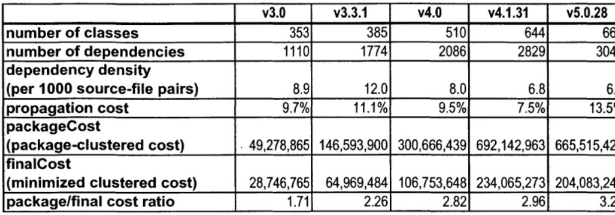
Table 2 shows the results of computing these metrics for several successive versions of
the entire Tomcat codebase, including Jasper:
-Ov3.
v3.3.1
v4.0
v4.1.31
v5.0.28number of classes 353 385 510 644 667
number of dependencies 1110 1774 2086 2829 3046
dependency density
(per 1000 source-file pairs) 8.9 12.0 8.0 6.8 6.9
propagation cost 9.7% 11.1% 9.5% 7.5% 13.5%
packageCost
(package-clustered cost) 49,278,865 146,593,900 300,666,439 692,142,963 665,515,426 finalCost
(minimized clustered cost) 28,746,765 64,969,484 106,753,648 234,065,273 204,083,241
package/final cost ratio 1.71 2.26 2.82 2.96 3.26
Table 2 Results of modularity metrics for the full Tomcat server, across multiple versions.
Table 3 shows the results of computing these metrics for several successive versions of
the main modules of Tomcat, excluding Jasper:
v3.0
v3.3.1
v4.O
v4.1.31
v5.0.28 number of classes 256 261 296 527 463 number of dependencies 655 1143 1296 2215 1908 dependency density (per 1000 pairs) 10.0 16.8 14.8 8.0 8.9 propagation cost 10.5% 12.4% 14.8% 8.6% 18.4% packageCost (package-clustered cost) 16,810,352 52,410,152 78,413,781 422,668,174 267,120,315 finalCost(minimized clustered cost) 11,140,993 20,588,043 29,282,159 182,986,033 100,249,761
package/final cost ratio 1.51 2.55 2.68 2.31 2.66
Table 3: Results of modularity metrics for the main versions
module of the Tomcat server, across multiple
Discussion
From these results we can draw several important conclusions, both about the Tomcat
project and about the model itself.
-39-Asynchronous evolution and experimentation in a modular architecture
The DSM analysis reveals a design structure - two distinctly decoupled modules - that
allowed the asynchronous evolution of these two modules. From version 3.0 to version
3.3.1, and again from version 3.3.1 to version 4.0, the main module of Tomcat was
almost entirely rewritten or rearchitected, while the Jasper module was mostly
unchanged. Moreover, the change metrics reveal that there was a different rate of
experimentation in the two modules.
This is an example of the substitution operator proposed by Baldwin and Clark (2000) at
work in the software domain. Subsequent to Tomcat's donation to the Apache Software
Foundation, and its transformation into an open-source project, Apache members
redesigned and rewrote the Tomcat-main module. This branch, initially named
"Catalina," competed with the older version of Tomcat, and Apache members
contributing to the Tomcat project voted to select one of the two branches to be adopted
as the new primary version of Tomcat (Mazzocchi, 2006). Although it is difficult to
assess the exact reasons why one version was selected over the other (and, indeed,
different members may have chosen the new version for different reasons) we can infer
from the process itself, and from the result that a new architecture was selected, that some
advantage was conferred by substituting a new version.
Of course, this example does not prove the converse - that without the design structure described above, the substitution could not have occurred in this manner. However, the
formal properties of software dependencies suggest that this is the case: Had the two
modules been tightly coupled by strong code dependencies, changes in one would
-necessarily have forced changes in its dependent modules. What this example does show
is that, at least in this case, the theoretical ability to substitute a software module
conferred by the structure is actually useful in this open-source software development
environment.
Reflections on the modularity metrics
The metrics data show that, even where the architectural intent of a set of changes is to
refactor, simplify, and make the codebase more modular, code sprawl - the increase in
the overall size of the project - is a major risk.
The evolution from version 4.0, in which the Tomcat-main module was completely
replaced, to version 4.1.31, which was the "refactoring" of this rewritten module, to
5.0.38 is interesting, because the metrics give conflicting results.
During this timeframe, the overall size of the system increased. From version 4.0 to
version 4.1.31, the propagation cost decreased considerably - from 9.5% to 7.5% - which
suggests successful refactoring, but the clustered cost more than doubled. This may be a
result of the increase in number of modules, but it may also suggest a degradation of the
quality of the package structure. Indeed, an examination of the list of packages in the
DSM for this version reveals the re-introduction of several packages which were
eliminated in the version 4.0 rewrite. For this reason, we can conjecture from the data
that, while version 4.1.31 was is considered a "production-quality" release, and is
functionally stable, it was in a state of architectural flux at this point. The low
propagation cost may actually reflect the fragmentation of the version's base classes.
That is to say, the reintroduced packages may represent redundant functionality in the
-41-basic utility classes which are widely used throughout the system; because different
portions of the system use different pieces of redundant functionality, the propagation cost of changes in this area is lowered.
In contrast, in the transition from version 4.1.31 to version 5.0.28, the propagation cost increases very significantly, from 7.5% to 13.5%. However, the clustered cost actually decreases, which is very significant, given that the number of modules actually increased.
Examination of the list of packages in the DSM suggests that the increase in propagation cost resulted from the rationalization of the product's package structure and the removal of the redundant functionality - several packages that were eliminated in version 4.0,
then reintroduced in version 4.1.31, were again eliminated. However, this rationalization, and elimination of potentially redundant functionality increases the propagation cost, because more of the system depends on the same base classes.
The data suggest that the metrics are sensitive to the number of modules (source files or classes) under consideration. For this reason, special care must be taken when using these metrics to track the evolution of a project across time, because the number of
modules in a software project often changes. Increases and decreases in the values of these metrics are neither inherently good nor inherently bad. Rather, the metrics may be used to discover and highlight the nature of the system's design evolution.
-Chapter 4: Company 2 case study: Splitting to enable
substitution
Background
The product platform, and its conundrum
Company 2's product line is a family of web-based applications - software applications
which run on a server, and which allow user interaction through web pages. Examples of
such web applications include bulletin-board systems that allow users to post and read
messages; travel sites that allow users to make and view reservations; commerce sites
with "shopping cart" functionality; or any web site that integrates information stored on
other systems such as databases. (These examples do not necessarily correspond to
Company 2's actual product offerings.)
Company 2's applications are based on its product platform. The platform consists of a
J2EE Application Server; an application framework, which implements basic services
used by all of its applications; and a business logic engine, which implements more
advanced services also used broadly within the product family. Figure 9 shows a module
block diagram of this structure.
-43-Application Applicdon Appilconon Piattorm Business logic pldiirm camponents Ssrverihmswork - platibrm corrponhnt
Figure 9: Block architectural diagram of Company 2's product family, including both platform and application components.
The platform components are shown at the bottom of the diagram, with the applications
sitting on top. Arrows indicate the dependency relationships of the modules - the
applications depend on the platform components, and the higher-level platform
components depend on the framework/server component at the bottom.
This chapter will focus on the server/framework application component, upon which the
entire product family depends. It will examine the partial redesign of the platform
structure to increase modularity and create a new option for addressing a strategic
vulnerability.
The server/framework component is a J2EE-compliant application server. That is to say,
it is an application server which conforms to the design rules of the J2EE Specification.
- 44
If that were its only role, then another, third-party, J2EE-compliant could be substituted
for this portion of its functionality.
However, this component is not only a J2EE Server; it also contains framework
components, basic services on which the whole product platform and family rely.
Therefore, a commercially-available third-party application cannot be substituted
wholesale for this major platform component.
Moreover, this component contains licensed code - some parts of it were derived from
code which Company 2 licensed from another vendor - and this code could not be readily
separated from the rest of the platform.
This situation created distinct strategic risks for Company 2: The expiration of this
license agreement could prohibit Company 2 from releasing new versions of its software
containing the licensed code. Because this licensed code was intertwined with Company
2's product family, such an event could place Company 2's entire product family at risk!
Application of the dependency structure model to this example
Use of dependency-based analysis tofind a cleaving line
To address this problem, the company performed a limited restructuring of the
server/framework platform component. The design goal of the restructuring was to
isolate the licensed code into a separate module, for which a different third-party software
product could be substituted at a later date. This substitution could be performed by
Company 2, licensing the software component and integrating it directly into the
platform, or by customers, integrating the products in the field. The secondary goals
-were to perform this separation with minimal engineering effort, minimal code changes, and minimal technical risk.
In order to achieve these goals, engineers first determined what code was subject to license restrictions. This set of Java classes is denoted by L, the licensed code.
L = {code under license}
However, if this code is to be separated, all the code which requires it must also be separated. This set is denoted by RL, the classes which require licensed code.
RL = {all classes that require some class in L}
However, all of RL cannot simply be split off and substituted, because some of it is also required for the rest of the platform and application. At this stage, the set RL Of classes was examined by a group of engineers, who used their knowledge of the platform and applications to decide what should, and should not, be excluded from the platform. Any code which was required by other platform and application components cannot be
excluded from the platform.3
3 In this case it was most expedient for engineers to make the determination simply by examining the list. However, the operation could also be performed using formal dependency analysis: To perform this
operation formally, one could use the following steps. First let A be the set of all classes in the product family:
A = {all classes in the product family}
The define A' as all of the classes except those which require the licensed code: A'= A - RL
Let RA be the classes which are required by some class in A': -46
-Once the appropriate cleaving line was determined to split the server/framework
component into two separate modules, the code dependencies that violated the constraints
imposed by the separation were systematically eliminated.
RA = {all classes that are required by some class in A '}
Then the set of classes P which must be preserved in the platform, and therefore must be extricated from dependence upon the licensed code L is simply the intersection of the two requirements sets:
P=RL RA'
In order to do so, any dependencies which go from the preserved code to the licensed code must be broken. The set Dei,, is the set of dependencies which must be eliminated:
Dejin = {all dependencies from class i to classj such that i C P and
j
E RL -}
-Figure 10 illustrates the design structure of Server-2, prior to splitting. J2EE APII Server/ framework platform component
Figure 10: DSM of Server 2, before splitting. Note that the server/framework component is composed of a single, large module.
-48--. - -- ..- - ,. '-.- . .. -. I I1 .. i I- --r I I
In contrast, following engineering work to resolve the deleterious dependencies, the DSM
shows clearly that the main server/framework component no longer relies on the licensed
components. This is shown in Figure 11.
J2EE API' Server/ framework platform component Licensed server components
Figure 11: DSM of Server 2, after splitting. Components under third-party license have been separated into a new top-level module.
-49
-I&II
.
I -4
This new structure is illustrated by the block diagram in Figure 12:
Appliiond Application Applicstion
Platform
Business logic plitbrm componentsI
-I
- Serverlrninwork platlbrm1
CL r onent IServer add-on
Licensed
Server Componernt I I-I I .J2EE API
Figure 12: Block diagram of the restructured Company 2 product family, in which licensed components are separated from the main product platform.
Because no portion of the Company 2 platform or applications depends on the licensed
server components module, another implementation may be substituted for it, as long as
the substitute module conforms to the underlying design rules which are the interface
between the product family and the licensed code module. Because, in this case, the
design rules are defined by the J2EE API module, a third-party J2EE application server
can be used for this purpose. In fact, Company 2 supports this configuration.
- 50
This substitution scenario is illustrated by the following block diagram (Figure 13). The
company's product platform is unchanged, but the licensed server components are
acquired from a third-party J2EE-compliant server:
Applicaton
Applicadon
Applaon
Platform
BusInes bgc pimtbrm cornponents - Serve rnwork I lptbrrncornonent
1.-..-...
. .
...-..
ThIrd-party application server
Third-pirty Server Component
J2EAPI
... .-.-. . ...-. . .
I.
Figure 13: Block diagram of the restructured Company 2 product family, in which a third-party product has been substituted for licensed components previously contained in the platform.
-The following DSM (Figure 14) shows the structure of the Company 2 platform with the
licensed code eliminated, and running on a third-party application server.
A J2EE API.
B Server/framework component
X
C Business logic component
D Third-party Server components
X X
E Application 1
X X X
F Application 2
X X X
G Application 3
x
x
Figure 14: DSM showing the design structure of the Company 2 product family operating with a third-party J2EE server.
Modularity metrics
Table 4 shows the metrics results for the Company 2. Due to the large size of this
software system, the minimized clustered cost metric was not computed.
Before split After Split
number of classes
10603
12750
number of dependencies
54285
65114
dependency density
(per 1000 pairs)
0.5
0.4
propagation cost
18.7%
10.3%
packageCost
(package-clustered cost)
3,490,093,345,221
6,139,113,728,992
Table 4: Modularity metrics for the Company 2 product platform, before and after splitting.
The most notable change in these metrics is a significant decrease in propagation cost,
from 18.7% to 10.3%. It makes sense that the partitioning of the design structure in this
way would decrease the propagation cost, because the main "server/framework"
- 52