Desalination by Membrane Distillation using
Electrospun Polyamide Fiber Membranes with
Surface Fluorination by Chemical Vapor Deposition
The MIT Faculty has made this article openly available. Please share how this access benefits you. Your story matters.
Citation Guo, Fei, et al. “Desalination by Membrane Distillation Using
Electrospun Polyamide Fiber Membranes with Surface Fluorination by Chemical Vapor Deposition.” ACS Applied Materials & Interfaces 7, 15 (April 2015): 8225–8232 © 2015 American Chemical Society
As Published http://dx.doi.org/10.1021/acsami.5b01197
Publisher American Chemical Society (ACS)
Version Author's final manuscript
Citable link http://hdl.handle.net/1721.1/110950
Terms of Use Article is made available in accordance with the publisher's policy and may be subject to US copyright law. Please refer to the publisher's site for terms of use.
1
Desalination by Membrane Distillation using Electrospun
Polyamide Fiber Membranes with Surface Fluorination by
Chemical Vapor Deposition
Fei Guo a, Amelia Servi b, Andong Liu a, Karen K. Gleason a and Gregory C. Rutledge a,*
a Department of Chemical Engineering, Massachusetts Institute of Technology, 77
Massachusetts Avenue, Cambridge, MA 02139, USA
b Department of Mechanical Engineering, Massachusetts Institute of Technology, 77
Massachusetts Avenue, Cambridge, MA 02139, USA
ABSTRACT
Fibrous membranes of poly(trimethyl hexamethylene terephthalamide) (PA6(3)T) were fabricated by electrospinning and rendered hydrophobic by applying a conformal coating of poly-(1H,1H,2H,2H-perfluorodecyl acrylate) (PPFDA) using initiated chemical vapor deposition (iCVD). A set of iCVD-treated electrospun PA6(3)T fiber membranes with fiber diameters ranging from 0.25 to 1.8 µm were tested for desalination using the air gap membrane distillation configuration. Permeate fluxes of 2 to 11 kg/m2/hr were observed for temperature differentials of 20 °C to 45 °C between the feed stream and condenser plate, with rejections in excess of 99.98%. The liquid entry pressure was observed to increase dramatically, from 15 to 373 kPa with reduction in fiber diameter. Contrary to expectation, for a given feed temperature the permeate flux was observed to increase for membranes of decreasing fiber diameter. The results for permeate flux and salt rejection show that it is possible to construct membranes for membrane distillation even from intrinsically hydrophilic materials after surface modification by iCVD, and that the fiber diameter is shown to play an important role on the membrane distillation performance in terms of permeate flux, salt rejection, and liquid entry pressure.
2
INTRODUCTION
Membrane-based processes are used for a variety of separations, such as removal of trace volatile organics,1 concentration of juices and acids, and water-oil separation.2-4 All of these membrane-based processes are driven by a gradient in chemical potential. In most cases, this gradient is realized by differences in absolute pressure or concentration across the membrane. Membrane-based technologies enjoy numerous benefits over competing technologies, including modularity and scalability, compactness, and the utilization of low-grade waste and/or alternative energy sources.5-6
In recent years, the applications of membrane-based processes for desalination have been expanding rapidly. Reverse osmosis (RO) is the dominant membrane-based technology for desalination, and holds great potential for water treatment worldwide.7 However, the RO technology is limited to relatively modest salinities because the osmotic pressure that must be overcome in RO increases with the salt concentration in the feed. Thus, many brines (salt concentration > 3.5%) are not amenable to separation by RO because the large pressures that must be employed are both expensive, in terms of pumping costs, and often lead to compaction of the membranes. Scaling on the membrane surface can also be a problem.7
This limitation of the RO process to modest salinity can be avoided by the membrane distillation (MD) process, while retaining many of the benefits of a membrane-based technology.8-9 Unlike RO, MD relies primarily on differences in temperature across the membrane, rather than osmotic pressure, to create the necessary gradient in chemical potential that drives separation.10-11 In MD, the driving force for diffusive transport is the difference in vapor pressure, which varies exponentially with the temperatures of the feed and permeate streams, respectively, according to Antoine’s equation.10-12 Separation in MD is made possible by differences in vapor pressures among components of a liquid that does not wet the membrane, resulting in selective enrichment of one component over the other(s) in the vapor phase. MD has been known as an effective desalination technique for more than fifty years. It was introduced in the late 1960s,13-14 and patented by Bodell in 1963.15-16 MD-related research became very active in the 1980s due to the
3
availability of new membranes.17-21 Four major configurations of the MD system have
been proposed, which differ in how the permeate liquid is processed on the cold side of the membrane;22-23 these configurations are known as direct contact membrane distillation (DCMD),24-25 air gap membrane distillation (AGMD),26-27 sweep gas membrane distillation (SGMD),28-29 and vacuum membrane distillation (VMD).30-31
The membranes commonly used for MD are made of intrinsically hydrophobic materials, such as polypropylene (PP), and polytetrafluoroethylene (PTFE). Membranes made from these materials are commercially available. They are fabricated by a variety of processes, including phase inversion, stretching, sintering, or thermally induced phase separation.12,
32-33 More recently, electrospinning has been used to fabricate MD membranes.8, 34
Electrospinning is a simple and versatile method for producing nonwoven sheets of fibers in which the diameters of both the fibers and the spaces between them are reduced by one to two orders of magnitude relative to conventional fiber-based filters and membranes.
35-37 The fibers can be spun into structures having high porosity, small pore size and high
surface-to-volume ratio. In the MD application, the membrane hydrophobicity is a critical parameter in reducing the wettability of membranes. However, most inherently hydrophobic polymers are either soluble only in nonpolar solvents, making their processing by electrospinning difficult, or else systematic variation of their membrane structures has proven relatively difficult.
To circumvent this problem, we focus on electrospun membranes made of poly(trimethyl hexamethylene terephthalamide) (PA6(3)T). PA6(3)T is a polar amorphous polymer with a glass transition around 140°C. It can be electrospun into uniform fibers over a wide range of average fiber diameters.38-39 However, being a polyamide, PA6(3)T is inherently hydrophilic, so it is not suitable for use as an MD membrane in unmodified form. It is thus desirable to lower the fiber surface energy without changing the fiber structure.
Initiated chemical vapor deposition (iCVD) is an effective technique for membrane surface modification. Using electron micro-probe analysis (EMPA), Gupta et al.40 have
4
demonstrated that the iCVD process can fully coat the pore walls of a capillary pore membrane having pores of 3 µm diameter, to a depth of at least 240 µm. Similarly, Asatekin, et al.41 used EMPA to verify the presence of iCVD-coated fluorpolymer films
in the 50 nm diameter pores of track-etched polycarbonate membranes; they found a fluorine signal at the top and bottom of the 20 µm long pores, with the ratio of the signals depending on the deposition parameters. iCVD has previously been shown to be effective in conformally coating electrospun fibrous materials and rendering the resulting membranes superhydrophobic.42 The fluoropolymer coating significantly increases the hydrophobicity of the membrane due to its low surface energy, and thus it can be used to transform hydrophilic PA6(3)T membranes into hydrophobic membranes without changing the membrane structure.
In this work, a set of iCVD-treated electrospun PA6(3)T fiber membranes are developed and tested for desalination using the AGMD configuration. This configuration is relatively simple to implement, has low energy requirements and does not require a source of clean water.26 The effect of fiber diameter on the MD performance, liquid entry pressure and pore size distribution of the electrospun membranes are studied.
METHOD
Materials
Poly(trimethyl hexamethylene terephthalamide) (PA6(3)T, density = 1.12 g/cm3, glass transition Tg=140 °C, softening point 250 °C) was obtained from Scientific Polymer
Products Inc. The substituent methyl groups in PA6(3)T suppress crystallization, yielding an amorphous material at all temperatures that is more soluble in organic solvents and easier to process than semi-crystalline polyamides42. It has good mechanical properties. Dimethylformamide (DMF) (ACS reagent, > 99.8%) and formic acid (FA) (ACS reagent, 96%) were purchased from Sigma Aldrich, Inc. and used as solvents in this work. All materials were used without further purification.
5
Electrospun Fiber Membranes
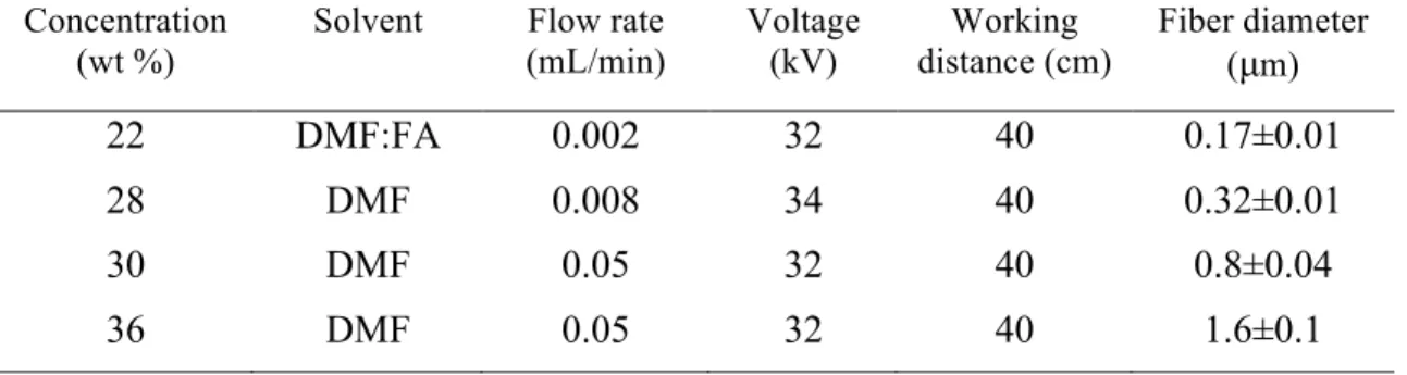
PA6(3)T solutions were prepared by dissolving the polymer in DMF, or a mixture of DMF and FA (mass ratio 99:1) where indicated (Table 1). The addition of formic acid (FA) to the PA6(3)T solution in small amounts modifies the solution conductivity, which is known to affect the diameter of fibers produced by electrospinning.38 The solutions were stirred for at least 10 hours at 80°C. The solutions with higher concentrations of PA6(3)T needed longer heating times to form homogeneous, transparent solutions. The solutions were cooled down to room temperature before electrospinning. A parallel-plate electrospinning setup was used in this work, as described in detail elsewhere.43 The operating conditions, such as flow rate, plate-to-plate distance, and voltage, are listed in Table 1. The electrospun fiber membranes were collected on a grounded aluminum foil at room temperature. The relative humidity was controlled at 25±4%. The membrane thickness was measured using an adjustable measuring force digital micrometer (Mutitoyo, Model CLM 1.6″ QM) with a contact force of 0.5 N. After spinning, the membranes were cut into pieces (4.5 cm x 9.5 cm) for further treatment and the membrane distillation test.
Table 1. Electrospinning processing parameters and the resulting average fiber diameters Concentration
(wt %)
Solvent Flow rate (mL/min) Voltage (kV) Working distance (cm) Fiber diameter (µm) 22 DMF:FA 0.002 32 40 0.17±0.01 28 DMF 0.008 34 40 0.32±0.01 30 DMF 0.05 32 40 0.8±0.04 36 DMF 0.05 32 40 1.6±0.1
Initiated Chemical Vapor Deposition
In order to increase the hydrophobicity of the electrospun PA6(3)T membranes, iCVD polymer coatings were applied to increase the fluorine content of their surfaces, as described elsewhere.42, 44-45 iCVD of poly(1H,1H,2H,2H-perfluorodecyl acrylate)
6
(PPFDA) 42, 45 was conducted using a custom-built reactor. The reaction chamber was
cylindrical with a diameter of 246 mm and a height of 38 mm. The top of the reaction chamber was covered with a removable 25 mm-thick transparent quartz plate. This transparent cover allowed in situ monitoring of the deposition through the use of laser interferometry (633 nm HeNe Laser, JDS Uniphase).
The (1H,1H,2H,2H-perfluorodecyl acrylate) (PFDA) monomer (97%, Aldrich) and the t-butyl peroxide initiator (98%, Aldrich) were used without further purification. The monomer was heated to 80 °C and fed into the chamber at a rate of 0.1 sccm. The initiator was kept at room temperature and was fed into the chamber at a rate of 1.0 sccm. PFDA condenses very easily, so the initiator to monomer ratio was kept high in order to keep the partial pressure of the PFDA low. Total pressure in the chamber was maintained at 200 mTorr throughout the deposition using a mechanical pump (45 CFM pumping speed, Alcatel). A leak rate of 0.1 sccm was recorded throughout the deposition. The reactor was equipped with an array of 14 parallel filaments (80% Ni, 20% Cr) resistively heated to 210 °C. The membranes were placed on a stage that was maintained at 25 °C using a recirculating chiller/heater (NESLAB). Sections of a plain silicon wafer and track-etched silicon wafers were placed on the stage alongside the membranes, to be used later to characterize the deposited films.
Two depositions were performed sequentially in order to coat all of the membranes. For both depositions, the coating thickness was monitored until it reached 200 nm on the silicon wafer, as determined by laser interferometry, at which point the filaments were turned off and deposition was halted. The first and second depositions took 18 minutes and 8 minutes, respectively; the difference in deposition times was attributed to residual PFDA in the chamber following the first deposition.
Contact Angle
The contact angles were measured using the sessile drop method by an advanced goniometer (model 500, Rame-Hart). The measurements of contact angle were taken within 30 s after depositing droplets of 20 µL DI water on the membrane surfaces. The reported values are averaged over ten measurements. For a porous membrane, there
7
often exists a stable (or metastable) Cassie-Baxter state 46 in which air trapped within the
pores of the membrane significantly increases the apparent contact angle of the water droplet relative to that exhibited on a smooth film of the same composition (the intrinsic contact angle).
Scanning Electron Microscopy
A JEOL 6010LA Scanning Electron Microscope (SEM) was used to image the fibrous membranes. Samples were sputter-coated with a less than 10 nm thick conductive layer of Au/Pd using a Desk II cold sputter unit (Denton Vacuum LLC) to facilitate imaging.
Liquid Entry Pressure
Liquid entry pressure (LEP) measures the propensity for intrusion of liquid into the pores of the membrane. If the LEP of a membrane is exceeded in the MD process due to excursions in salt concentration in the feed or in operating conditions such as pressure or temperature, the membrane becomes compromised; once the membrane is wetted, liquid can pass directly from the feed side to the permeate side without purification, resulting in loss of selectivity.
In this work, the LEP of the membrane was characterized using a custom-designed apparatus (see Figure S3 of Supplemental Information). In this apparatus, a syringe pump was used to generate an applied pressure on the liquid above the test membrane by pumping the liquid with a very low but constant flow rate (0.5 mL/min in this work). The test membrane was supported by a stainless steel filter holder (Advantec, filter size: dia. 13 mm, effective filtration area: 0.9 cm2). During the test, the hydrostatic pressure increased until it exceeded the capillary pressure that prevents the liquid from wetting the test membrane. The gauge pressure was monitored using a pressure sensor (USB output PX409, Omega). The highest pressure recorded by the sensor was interpreted as the LEP, or breakthrough pressure, of the test sample.
8
Pore diameter also influences the LEP as well as the mass transfer efficiency through a membrane. For uniform cylindrical pores, the pore diameter can be estimated by imaging methods, such as SEM or optical microscopy. However, the electrospun membranes have fibrous structures with randomly oriented fibers and irregular pores. A 2D image only shows a superficial view of the fiber membrane, with limited depth resolution. The estimated pore diameter based on imaging can change significantly depending on contrast or brightness during imaging.
Several methods have been reported in the literature to determine the pore diameter distribution of fibrous membranes based on the pressure required to intrude a nonwetting fluid into the pores or extrude a wetting fluid from the pores. These methods include mercury porosimetry,47-48 and capillary flow porometry (CFP).49 In all of these methods, a model for the pore geometry is required to convert the measured pressure to a characteristic pore diameter. In this work, LEP is also used to quantify the pore diameter. The configuration employed to measure LEP here is similar to that used in CFP, except that a nonwetting fluid is intruded into the membrane rather a wetting fluid extruded. It should be mentioned that the pore diameter estimated by the LEP measurement is roughly the largest throat diameter of a channel that spans the membrane thickness, similar to the bubble point measured in CFP, because the smaller pores need higher pressures to break through.
As a check, mercury porosimetry was also used to measure the pore diameter in this work. The porosity and the pore size distributions of the electrospun fiber membranes were measured using an Autopore IV porosimeter (Micromeritics, Norcross, GA). The sample membranes were cut and folded into small rectangular pieces to fit in the penetrometer. The mass of each sample was around 0.1 g. While this method permits the determination of the entire pore size distribution in principle, the required pressures are much higher than in the LEP measurement. As a result, compression of the membrane can be a source of error in the pore diameter distribution, unless suitable corrections are made.47 In this work, only the diameter corresponding to the peak in the log of differential intrusion vs.
9
pressure was used to characterize the pore diameter of the membranes. In addition to the usual Young-Laplace equation, several other equations specific to fibrous materials were used to convert pressure to pore diameter, and their results are compared.
Membrane Distillation
Membrane distillation performance was characterized using a lab-scale Air Gap Membrane Distillation (AGMD) unit (Figure 1). The feed was saline water with 3.5 wt% sodium chloride (NaCl), a salt concentration comparable to most seawater. The temperature of the feed was precisely controlled by a water bath, and varied between 40 and 80 °C. The temperature of the cooling side was maintained at 25°C by circulating a relatively large amount of water through an air cooling system. ΔT is reported as the temperature difference between the feed and cooling streams; temperature gradients due to thermal polarization on either side of the membrane are not considered. The condensing plate was made of a stainless steel (thickness: 0.5 mm).
The test membrane was tightly sealed in the module (CF042AC, Sterlitech) using a rubber sheet as a gasket (Buna-N/Nitrile Rubber, thickness: 0.25'') (see Figure S1 of Supplemental Information). The effective MD area was 36 cm2 (4 cm x 9 cm). Test membranes were supported by a polypropylene (square) mesh (2.4 mm openings, estimated thickness: ~ 2 mm). The mesh spacer in the feed side served not only as a membrane support but also as a turbulence promoter that could reduce the thermal polarization on the feed side of the membrane.12, 50
10
Figure 1. The schematic diagram of (a) the AGMD lab scale unit used in this work, and (b) the expanded diagram of AGMD module configuration. The air gap was provided and supported by polypropylene (square) mesh. The air gap was considered to be the same thickness as that of the supporting mesh (~ 2 mm).
The circulating flow of the system was generated by magnetically driven, precision-geared pumps (Micropump A-Mount Cavity Style Pump) that provide smooth, accurate, pulseless fluid delivery. The flow rates of the feed and coolant were 1.2 L/min. The temperatures and pressures at the inlets and outlets were monitored by pipe plug thermocouple probes (Digi-Sense Type-J) and pressure gauges (WIKA Instrument, LP). The permeate water was collected as it dripped out of a tube exiting the system and was automatically weighted every 60 seconds by a digital balance linked to a computer with data logging. Each sample was tested in this AGMD system for 3 hours. The permeate flux at constant temperature was very stable, with R-squared values generally larger than 99.9%, as shown in Figure S2 (Supplemental Information).
The salt concentration of the permeate water was measured by a chloride ion-selective electrode (Vernier); this method was preferred over the conventional conductivity meter in order to eliminate the effect of carbon dioxide absorbed from the air. Carbon dioxide absorbed by water from the air results in the formation of charged ions (e.g. bicarbonate), thereby increasing the conductivity of the water. The chloride ion concentration can be converted easily into the concentration of the salt (sodium chloride). In the AGMD configuration, the cooling water is only used to remove the heat from the condensing
11
plate; there is no mixing with the permeate water, so the salt rejection (R) is simply calculated based on the chloride ion concentrations in the feed and permeate streams.
𝑅 = 1 − 𝐶𝑙 ! !"#$ 𝐶𝑙! !""# (1)
RESULTS AND DISCUSSION
Electrospinning
As shown in Figure 2a-d, the PA6(3)T was electrospun into nonwoven membranes with uniform fiber diameters. The average fiber diameters of the membranes ranged over an order of magnitude, from 0.17 µm to 1.6 µm based on analysis of SEM images, made possible by variations in solvent composition and polymer concentration as well as processing parameters (Table 1). All the fibers employed in this work were smooth and regular in structure. The thicknesses of the electrospun membranes were 55±2 µm, measured by micrometer.
Figure 2. (a-d) SEM images of as-spun PA6(3)T fibers. (e-h) SEM images of the fiber corresponding to a through d, respectively, after conformal coating with PPFDA by iCVD. (scale bar: 1 µm). The contact angle (CA) was 124 ° for a flat Si substrate which
12
was treated by iCVD of PPFDA under the same conditions. The CA for the as-spun membranes was 0 ° (spontaneously wetting) in all cases.
iCVD Coating of PPFDA
Figure 2e-h show that the fibers maintained the smooth surface after the iCVD treatment, but there was a slight increase in the fiber diameter. It is difficult to measure directly the thickness of the coating, but the SEM images show that the fiber diameters increased on average by 0.08 µm to 0.3 µm. Thus the thickness of the coating was 0.04 µm to 0.15 µm, with the smaller fibers having thinner coatings. A coating thickness of 0.2 µm was measured on a reference silicon wafer under the same iCVD conditions. The thickness on the silicon wafer is larger than that on the fibers, possibly due to the high surface areas of the electrospun fiber membranes compared to a flat silicon surface. The coatings all appear to be uniform and conformal.
The contact angles (CA) for water on all the PPFDA-coated PA6(3)T fiber membranes are provided in Figure 2. As a result of the iCVD treatment, the as-spun membranes were transformed from hydrophilic (CA much smaller than 90°) to hydrophobic (CA higher than 90°). In the latter case, the apparent contact angles are all higher than 130°. The membranes with smaller fibers are more hydrophobic than those with larger fibers. The highest contact angle obtained was 151±2°, for the membrane with the smallest fiber diameter (Figure 2e).
Liquid Entry Pressure
All of the as-spun PA6(3)T fiber membranes exhibited negligible LEP values (peak pressures). After the iCVD treatment to coat the PA6(3)T fiber membranes conformally with PPFDA, there was a dramatic enhancement of LEP for some of the membranes. As shown in Figure 3, the LEP of the electrospun fiber membrane after iCVD treatment
13
increased as the fiber diameter decreased. The mercury porosimetry data confirm this trend. The significant difference in the pressures required is attributed in part to the higher surface tension of mercury compared to that for water (485 vs 72 mN/m at 25°C), but also compression of the sample at the higher intrusion pressures.51 The porosities of the membranes as measured by mercury porosimetry were 0.69, 0.77, 0.86 and 0.84 for the membranes with fiber diameters of 0.25, 0.43, 1.1 and 1.8 µm, respectively.
Temperature and salt concentration can also influence the LEP, because these two factors alter the surface tension of an aqueous solution. Decreasing temperature12, 50 or increasing content of inorganic salt 52 increases water surface tension, and thus increases the LEP. The effect of salt on LEP was studied using a 3.5 wt% sodium chloride solution having the same salt concentration as normal sea water. The liquid entry pressure for the saline was only slightly higher than that for the DI water (400 vs. 373 kPa), for the same hydrophobic membrane (iCVD treated membrane, fiber diameter, 0.25 µm). Attempts to measure the effect of temperature on LEP were confounded by transients in the apparatus required to equilibrate the membrane at higher temperatures. Nevertheless, the trend in LEP at high temperature should mimic that at room temperature, shown in Figure 3, albeit shifted downward by the ratio of surface tensions (72 and 65 mN/m at 25° and 65°C, respectively).
14
Figure 3. LEPs of iCVD-treated electrospun PA6(3)T membranes having various fiber diameters, with DI water (T=25 °C). Mercury porosimetry data showing the relationship between the mercury entry pressure (peak pressure) and the fiber diameter of the electrospun fiber membranes.
Pore Diameter
For membranes with cylindrical pores of sufficiently small diameter (Figure 4a), the relationship between the intrusion (or extrusion) pressure and pore radius can be estimated by the Young-Laplace equation:52
𝑠 = −2𝛾 cos 𝜃 /∆𝑃 (2)
where s is the pore radius, ∆𝑃 is the pressure difference between the liquid and vapor phases, 𝛾 is the liquid surface tension, and 𝜃 is the intrinsic contact angle of the material (i.e. the contact angle θ that water drops would establish on a smooth, nonporous surface of the material). The interpretation of mercury porosimetry data is also usually based on this assumption.
However, fibrous membranes do not have this kind of regular, cylindrical pore structure. As evident from Figure 2, these membranes have very irregularly shaped, highly inter-connected pore spaces. To characterize the intrusion (or extrusion) of liquid from fibrous
15
matrices such as these, other models are more appropriate than that of Young and Laplace. For example, Rijke derived a model, illustrated in Figure 4b, for liquid contact on membranes comprising parallel fibers:53
𝑠 = 𝑟 𝛾
𝑟∆𝑃− cos 𝜃 !
+ sin!𝜃 − 1
(3)
where r is the radius of the fibers.
Tuteja et al. also proposed two models for the intrusion pressure for various “re-entrant” surfaces, including those comprising parallel fibers. One of these models (the robustness height, or H* model) is based on the idea that the transition from the composite (Cassie-Baster) interface to the fully wetted interface54 occurs through deflection of the interface to an extent equal to the height of the flat (equilibrium) interface above the bottom of the fibers, as shown in Figure 4c. In this model, a positive external pressure is required to force liquid through a fibrous membrane even if it has an intrinsic contact angle less than 90°, because there exists a 3-phase contact line equilibrium somewhere along the re-entrant curvature of the bottom half of the fiber. The H* model is represented by eqn (4). The second model proposed by Tuteja et al is based on the robustness angle, or T* model, in which the 3-phase contact line can move across the re-entrant surface in response to an applied pressure. The T* model is represented by eqn. (5).54 Tuteja's T* model is similar in form to earlier models proposed by Crisp and Thorpe (1948),55 and by Purcell (1949).56
𝑠 = 2𝛾 1 − cos 𝜃 r/∆𝑃 (4)
𝑠 = 𝛾 sin 𝜃 /(2∆𝑃) (5)
Figure 4d shows the relationship between inter-fiber distance (2s), analogous to pore diameter, and the intrusion pressure for DI water at 25 °C (γ= 72 mN/m) for a
16
hypothetical membrane with monodisperse fiber diameter (0.43 µm), based on the three models. For electrospun fiber membranes, the fiber diameter can be estimated from SEM images, and the LEP can be measured as described previously in this work. A measure of pore size can be calculated by equating the LEP with the intrusion pressure in each of the models; thus, the relationship between fiber diameter and the pore diameter shown in Figure 4e was obtained. It is apparent that, for electrospun membranes, the pore diameter increases with the fiber diameter.
The mercury porosimetry analysis is based on the Young-Laplace model. Figure 3 shows the relationship between the Hg entry pressure (peak pressure) and the fiber diameter, which is relevant to the pore size of electrospun fiber membranes.
Figure 4. (a) Schematic of the liquid-vapor interface in a regular cylindrical pore of a hydrophobic membrane (Young-Laplace model): solid phase (red), liquid phase (blue), vapor phase (white). (b) Schematic of the cross-section of two parallel fibers with their
17
axes perpendicular to the plane of the paper (Rijke model). (c) Schematic of the cross-section of two parallel fibers as in (b), highlighting the liquid-vapor interface with an equilibrium contact angle < 90° (Tuteja models). (d) The relationship between the pore size and the intrusion pressure based on four models for a membrane with fiber diameter 0.43 µm. (e) The relationship between pore diameter (2s) and fiber diameter, where pore size has been calculated by equating the LEP with intrusion pressure, using the different models. The value of the contact angle used here is the intrinsic contact angle (124°) of water on a flat Si substrate that was coated with PPFDA by iCVD. The surface tension of water is 72 mN/m at room temperature.
Membrane Distillation Performance
The results of the AGMD experiments are shown in Figure 5 for feed temperatures up to 70°C (ΔT=45°C). The permeate flux is observed to vary between 2 and 11 kg/m2/hr over a range of ΔT’s spanning about 20–25°C for each membrane. Two of the membranes (d=0.25 and 1.10 mm) exhibited a slightly stronger temperature dependence of flux, which we attribute to small differences in compressibility of the membranes and to variations in the flow distribution through the mesh on the feed side. All of the sample membranes yielded very high salt rejection rates (>99.98%) when ΔT<45°C. At feed temperatures above 70°C, the salt rejection rates of the membranes with larger fiber diameters (>1 µm) were observed to decline (Table S1, Supplemental Information), indicative of wetting of the membrane and passage of the saline liquid through to the permeate. This failure of the membranes at high feed temperature was attributed to a decline in LEP, due to reduction of surface tension at higher temperature. The membranes with smaller fiber diameter (<0.5 µm) did not show such declines in salt rejection, even up to ΔT=52 °C (salt rejection=99.99%); this accords with observation of higher LEP with smaller fiber diameter (Figure 3).
Significantly, for a given ΔT between ~20 and 45°C the permeate flux apparently increases with decreasing fiber diameter within the membrane, according to Figure 5. This result runs contrary to expectation, since the Knudsen number Kn=λ/2s increases from about 0.01 to 0.25 (using the Young-Laplace equation for pore diameter) with decreasing fiber diameter from 1.8 to 0.25 µm in this work. Here, λ is the mean free path of water vapor, which is about 0.11 µm at 60°C and 1 atm.57 The larger values of Kn are
18
well within the transition regime for diffusivity in fibrous media, for which the relation is a good approximation.58 Here, ε and τ are porosity and tortuosity, respectively, while Db and Deff are the bulk self-diffusion coefficient and the effective
diffusion coefficient, respectively. In this regime, the mechanisms of both Knudsen diffusion and molecular diffusion are expected to be operative. This behavior differs from pressure-driven flow, where slip at the fiber surface increases with increasing Kn. The trend in permeate flux with fiber diameter cannot be traced to differences in membrane thickness, which are negligible for the samples employed here, or to differences in porosity, which apparently decreases with decreasing fiber diameter. We are left with the conclusion that the subtle differences in the structure of the electrospun mats comprising fibers of different average diameter give rise to noticeable variations in tortuosity. One such difference could be the increased “curl” observed previously in elecrospun mats of PA6(3)T with smaller fiber diameter, which was used to account for variations in the mechanical behavior of electrospun mats with fiber diameter.38, 59 The membrane with the smallest fiber diameter, around 0.25 µm, would have the greatest “curl”, and showed the highest permeate flux under the operating conditions explored in this work. Alternatively, surface diffusion could be partly responsible for the enhanced flux, since the membrane with the smallest fiber diameter is also the one with the highest specific surface area. The hydrophobicity of PPFDA (water contact angle =124 ° for a PPFDA-coated flat Si substrate) makes the adsorption of water layers on the coated fibers seem unlikely, however. Resolution of this question warrants further investigation.
(
Kn)
D
19
Figure 5. The MD performance in terms of permeate flux of a set of PPFDA-iCVD treated PA6(3)T membranes with different fiber diameters. All the membranes have similar thickness (~ 55 µm).
CONCLUSION
Hydrophilic electrospun fiber membranes can be rendered hydrophobic by iCVD of a conformal low surface energy coating on the fibers. This opens up the possibility for better control of membrane morphology through processing of a broader range of membrane compositions, and decouples the fiber-forming requirements from the surface energy requirements needed for liquid-vapor separation applications such as MD. By taking advantage of using a hydrophilic polymer like PA6(3)T that can be spun into fibers with a wide range of fiber diameters, we have expanded the range of materials that can be considered for fabrication of electrospun MD membranes.
In the MD application using electrospun fiber membranes, the membranes with smaller fibers are preferred because they exhibit higher liquid entry pressure and higher permeate flux. The higher LEP is readily understood to be the consequence of the proportionality
15 20 25 30 35 40 45 0 2 4 6 8 10 12 d=0.25 µm d=0.43 µm d=1.10 µm d=1.80 µm Temperature Difference (oC) P er meate Flux (kg/m 2 /hr )
20
between fiber diameter and pore diameter in electrospun membranes. The higher permeate flux is contrary to expectation, but suggests that subtle changes in membrane morphology with decreasing fiber diameter may be responsible. The salt rejection rates are very high over a wide range of temperature differences. The membranes with relatively large fiber diameters (e.g. 1.1 µm and 1.8 µm) can still be applied in MD; however, their relatively large pore sizes result in very low LEPs, which reduces their application range.
ASSOCIATED CONTENT Supporting Information
The lab scale units for the AGMD and LEP measurements, LEP of membranes under various conditions, stable permeate flux, the MD performance in terms of salt rejection. This material is available free of charge via the Internet at http://pubs.acs.org.
AUTHOR INFORMATION Corresponding Author *Professor Gregory Rutledge Phone: 617.253.0171
Fax: 617.253.2701 Email: rutledge@mit.edu
ACKNOWLEDGMENTS
This research was supported by the Cooperative Agreement between the Masdar Institute of Science and Technology (Masdar Institute), Abu Dhabi, UAE and the Massachusetts Institute of Technology (MIT), Cambridge, MA, USA - Reference
02/MI/MI/CP/11/07633/GEN/G/00. The authors would also like to acknowledge the MIT Institute of Soldier Nanotechnology (ISN) for the use of its facilities.
21
REFERENCES
(1) Sudoh, M.; Takuwa, K.; Iizuka, H.; Nagamatsuya, K. Effects of Thermal and Concentration Boundary Layers on Vapor Permeation in Membrane Distillation of Aqueous Lithium Bromide Solution. J. Membr. Sci. 1997, 131, 1- 7.
(2) Tomaszewska, M.; Gryta, M.; Morawski, A. W. Study on the Concentration of Acids by Membrane Distillation. J. Membr. Sci. 1995, 102, 113- 122.
(3) Calabro, V.; Jiao, B. L.; Drioli, E. Theoretical and Experimental-Study on Membrane Distillation in the Concentration of Orange Juice. Ind. Eng. Chem. Res. 1994,
33, 1803-1808.
(4) Gryta, M.; Karakulski, K. The Application of Membrane Distillation for The Concentration of Oil-Water Emulsions. Desalination 1999, 121, 23- 29.
(5) Camacho, L. M.; Dumee, L.; Zhang, J. H.; Li, J. D.; Duke, M.; Gomez, J.; Gray, S. Advances in Membrane Distillation for Water Desalination and Purification Applications.
Water 2013, 5, 94-196.
(6) Khayet, M.; Matsuura, T. Membrane Distillation : Principles and Applications. Elsevier: Amersterdam; Boston, 2011; 477 p.
(7) Greenlee, L. F.; Lawler, D. F.; Freeman, B. D.; Marrot, B.; Moulin, P. Reverse Osmosis Desalination: Water Sources, Technology, and Today's Challenges. Water Res. 2009, 43, 2317- 2348.
(8) Feng, C.; Khulbe, K. C.; Matsuura, I.; Gopal, R.; Kaur, S.; Rarnakrishna, S.; Khayet, A. Production of Drinking Water from Saline Water by Air-Gap Membrane Distillation Using Polyvinylidene Fluoride Nanofiber Membrane. J. Membr.Sci. 2008,
311, 1-6.
(9) Lalia, B. S.; Guillen-Burrieza, E.; Arafat, H. A.; Hashaikeh, R. Fabrication And Characterization of Polyvinylidenefluoride-Co-Hexafluoropropylene (PVDF-HFP) Electrospun Membranes for Direct Contact Membrane Distillation. J. Membr. Sci. 2013,
428, 104-115.
(10) Lawson, K. W.; Lloyd, D. R. Membrane Distillation. J. Membr. Sci. 1997, 124, 1-25.
(11) Schneider, K.; Vangassel, T. J. Membrane Distillation. Chem. Ing. Technol. 1984,
22
(12) Zhang, J. H.; Dow, N.; Duke, M.; Ostarcevic, E.; Li, J. D.; Gray, S. Identification Of Material and Physical Features of Membrane Distillation Membranes for High Performance Desalination. J. Membr. Sci. 2010, 349, 295-303.
(13) Weyl, P. K. Recoveryo of Demineralized Water from Saline Waters. US Patent 3340186, 1967.
(14) Findley, M. E. Vaporization through Porous Membranes. Ind. Eng. Chem. Proc.
Des. Dev. 1967, 6, 226-230.
(15) Bodell, B. R. Distillation of Saline Water Using Silicone Rubber Membrane. US Patent 3361645: 1968.
(16) Bodell, B. R. Silicon Rubber Vapour Diffusion in Saline Water Distillation. US Patent 285032: 1963.
(17) Hanbury, W. T.; Hodgkiess, T. Membrane Distillation - An Assessment.
Desalination 1985, 56, 287-297.
(18) Schofield, R. W.; Fane, A. G.; Fell, C. J. D. Heat and Mass-Transfer in Membrane Distillation. J. Membr. Sci. 1987, 33, 299-313.
(19) Carlsson, L. The New Generation in Sea-Water Desalination Su Membrane Distillation System. Desalination 1983, 45 (May), 221-222.
(20) Andersson, S. I.; Kjellander, N.; Rodesjo, B. Design and Field-Tests of a New Membrane Distillation Desalination Process. Desalination 1985, 56, 345-354.
(21) Smolders, K.; Franken, A. C. M. Terminology for Membrane Distillation.
Desalination 1989, 72, 249-262.
(22) Alklaibi, A. M.; Lior, N. Membrane-Distillation Desalination: Status and Potential.
Desalination 2005, 171, 111-131.
(23) Khayet, M. Membranes and Theoretical Modeling of Membrane Distillation: A Review. Adv. Colloid Interface Sci. 2011, 164, 56-88.
(24) Martinez, L.; Florido-Diaz, F. J. Theoretical and Experimental Studies on Desalination Using Membrane Distillation. Desalination 2001, 139, 373-379.
(25) Francis, L.; Maab, H.; AlSaadi, A.; Nunes, S.; Ghaffour, N.; Amy, G. L. Fabrication of Electrospun Nanofibrous Membranes for Membrane Distillation Application. Desalin. Water Treat. 2013, 51, 1337-1343.
(26) Jonsson, A. S.; Wimmerstedt, R.; Harrysson, A. C. Membrane Distillation - A Theoretical-Study of Evaporation through Microporous Membranes. Desalination 1985,
23
(27) Cipollina, A.; Di Sparti, M. G.; Tamburini, A.; Micale, G. Development of Membrane Distillation Module for Solar Energy Seawater Desalination. Chem. Eng. Res.
Des. 2012, 90, 2101-2121.
(28) Basini, L.; Dangelo, G.; Gobbi, M.; Sarti, G. C.; Gostoli, C. A Desalination Process through Sweeping Gas Membrane Distillation. Desalination 1987, 64, 245-257.
(29) Khayet, M.; Godino, P.; Mengual, J. I. Nature of Flow on Sweeping Gas Membrane Distillation. J. Membr. Sci. 2000, 170, 243-255.
(30) Bandini, S.; Gostoli, C.; Sarti, G. C. Separation Efficiency in Vacuum Membrane Distillation. J. Membr.Sci. 1992, 73, 217-229.
(31) Sarti, G. C.; Gostoli, C.; Bandini, S. Extraction of Organic-Components from Aqueous Streams by Vacuum Membrane Distillation. J. Membr. Sci. 1993, 80, 21-33. (32) Jiao, B.; Cassano, A.; Drioli, E. Recent Advances on Membrane Processes for The Concentration of Fruit Juices: A Review. J. Food Eng. 2004, 63, 303-324.
(33) Curcio, E.; Drioli, E. Membrane Distillation and Related Operations - A Review.
Sep. Purif. Rev. 2005, 34, 35-86.
(34) Subramanian, S.; Ramakrishna, S. New Directions in Nanofiltration Applications - Are Nanofibers The Right Materials as Membranes in Desalination? Desalination 2013,
308, 198-208.
(35) Khayet, M.; Matsuura, T. Membrane Distillation Principles and Applications.
Elsevier 2011.
(36) Lloyd, D. R.; Kinzer, K. E.; Tseng, H. S. Microporous Membrane Formation via Thermally Induced Phase-Separation .1. Solid Liquid-Phase Separation. J. Membr. Sci. 1990, 52, 239-261.
(37) Tomaszewska, M. Preparation and Properties of Flat-Sheet Membranes from Poly(Vinylidene Fluoride) for Membrane Distillation. Desalination 1996, 104, 1-11. (38) Pai, C. L.; Boyce, M. C.; Rutledge, G. C. Mechanical Properties of Individual Electrospun PA 6(3)T Fibers and Their Variation with Fiber Diameter. Polymer 2011, 52, 2295-2301.
(39) Mannarino, M. M.; Rutledge, G. C. Mechanical and Tribological Properties of Electrospun PA 6(3)T Fiber Mats. Polymer 2012, 53, 3017-3025.
(40) Gupta, M.; Kapur, V.; Pinkerton, N. M.; Gleason, K. K. Initiated Chemical Vapor Deposition (iCVD) of Conformal Polymeric Nanocoatings For The Surface Modification Of High-Aspect-Ratio Pores. Chem. Mater. 2008, 20, 1646-1651.
24
(41) Asatekin, A.; Gleason, K. K. Polymeric Nanopore Membranes for Hydrophobicity-Based Separations by Conformal Initiated Chemical Vapor Deposition. Nano Lett. 2011,
11, 677-686.
(42) Ma, M. L.; Mao, Y.; Gupta, M.; Gleason, K. K.; Rutledge, G. C. Superhydrophobic Fabrics Produced by Electrospinning and Chemical Vapor Deposition. Macromolecules 2005, 38, 9742- 9748.
(43) Shin, Y. M.; Hohman, M. M.; Brenner, M. P.; Rutledge, G. C. Experimental Characterization of Electrospinning: The Electrically Forced Jet And Instabilities.
Polymer 2001, 42, 9955- 9967.
(44) Gleason, K. K.; Rutledge, G. C.; Gupta, M.; Ma, M.; Mao, Y. Superhydrophobic Fibers Produced by Electrospinning and Chemical Vapor Deposition. US Patent 7651760: 2010.
(45) Coclite, A. M.; Shi, Y. J.; Gleason, K. K. Controlling the Degree of Crystallinity and Preferred Crystallographic Orientation in Poly-Perfluorodecylacrylate Thin Films by Initiated Chemical Vapor Deposition. Adv. Funct. Mater. 2012, 22, 2167-2176.
(46) Cassie, A. B. D.; Baxter, S. Wettability of Porous Surfaces. T. Faraday Soc. 1944,
40, 0546-0550.
(47) Rutledge, G. C.; Lowery, J. L.; Pai, C. L. Characterization by Mercury Porosimetry of Nonwoven Fiber Media with Deformation. J. Eng. Fiber Fabr. 2009, 4, 1-13.
(48) Lowery, J. L.; Datta, N.; Rutledge, G. C. Effect of Fiber Diameter, Pore Size And Seeding Method on Growth of Human Dermal Fibroblasts in Electrospun Poly(Epsilon-Caprolactone) Fibrous Mats. Biomaterials 2010, 31, 491-504.
(49) Nakao, S. Determination of Pore-Size and Pore-Size Distribution .39 Filtration Membranes. J. Membr. Sci. 1994, 96, 131-165.
(50) Zhang, J. H.; Gray, S.; Li, J. D. Modelling Heat and Mass Transfers in DCMD Using Compressible Membranes. J. Membr. Sci. 2012, 387, 7-16.
(51) Choong, L. T.; Mannarino, M. M.; Basu, S.; Rutledge, G. C. Compressibility of Electrospun Fiber Mats. J. Mater. Sci. 2013, 48, 7827- 7836.
(52) Vargaftik, N. B.; Volkov, B. N.; Voljak, L. D. International Tables of the Surface Tension of Water. J. Phys. Chem. Ref. Data 1983, 12, 817- 820.
(53) Rijke, A. M. Wettability and Phylogenetic Development of Feather Structure in Water Birds. J. Exp. Biol. 1970, 52, 469-479.
(54) Tuteja, A.; Choi, W.; Mabry, J. M.; McKinley, G. H.; Cohen, R. E. Robust Omniphobic Surfaces. P. Natl. Acad. Sci. USA 2008, 105, 18200-18205.
25
(55) Crisp, D. J.; Thorpe, W. H. The Water-Protecting Properties of Insect Hairs.
Discuss Faraday Soc. 1948, 3, 210-220.
(56) Purcell, W. R. Capillary Pressures - Their Measurement Using Mercury and the Calculation of Permeability Therefrom. J. Pet. Technol.1949, 186, 39-48.
(57) Alkhudhiri, A.; Darwish, N.; Hilal, N. Membrane Distillation: A Comprehensive Review. Desalination 2012, 287, 2-18.
(58) Tomadakis, M. M.; Sotirchos, S. V. Ordinary and Transition Regime Diffusion in Random Fiber Structures. AIChE J. 1993, 39, 397-412.
(59) Silberstein, M. N.; Pai, C. L.; Rutledge, G. C.; Boyce, M. C. Elastic-Plastic Behavior of Non-Woven Fibrous Mats. J. Mech. Phys. Solids. 2012, 60, 295-318.
26
TOC
A schematic illustration of this work
Desalination by Membrane Distillation using Electrospun Polyamide Fiber Membranes with Surface Fluorination by Chemical Vapor Deposition