ORIGINAL PAPER
3D Surface Measurement for Medical
Application
—Technical Comparison of Two Established
Industrial Surface Scanning Systems
K. Schwenzer-Zimmerer&J. Haberstok&L. Kovacs&B. I. Boerner&N. Schwenzer&P. Juergens& H.-F. Zeilhofer&C. Holberg
Received: 31 August 2007 / Accepted: 3 October 2007 / Published online: 19 October 2007
# Springer Science + Business Media, LLC 2007
Abstract In 3D mapping of flexible surfaces (e.g. human faces) measurement errors due to movement or positioning occur. Aggravated by equipment- or researcher-caused mistakes considerable deviations can result. Therefore first the appliances’ precision handling and reliability in clinical environment must be established. Aim of this study was to investigate accuracy and precision of two contact-free 3D measurement systems (white light vs. laser). Standard specimens of known diameter for sphere deviation, touch deviation and plane deviation were tested. Both systems are appropriate for medical application acquiring solid data
(<mm). The more complex white-light system shows better accuracy at 0.2 s measuring time. The laser system is superior concerning robustness, while accuracy is poorer and input time (1.5–2.5 s) longer. Due to the clinical demand the white-light system is superior in a laboratory environment, while the laser system is easier to handle under non-laboratory conditions.
Keywords 3D imaging . Surface scanning . Laser . White light
Introduction
The availability of three-dimensional data of body surfaces (e.g. the face), unlike direct measurement [1] or formerly two-dimensional representation (photo/film), is becoming increasingly important in many medical specialities for example anthropometry, plastic and maxillo-facial surgery, neurosurgery and visceral surgery [2–5].
In order to apply surface scanners to medicine, one usually has to resort to commercially produced systems originally designed for industrial use. In addition to photogrammetric systems [6], measuring systems with higher resolution like surface scanners based on structured white light [7], as well as linear laser scanners [8] are available. The transfer of appliances from the industrial to the medical sector does not always go smoothly [9, 10]. Any system that involves patients must be absolutely innocuous with respect to health concerns. In order to acquire precise, detailed 3D images of facial structures, in the nasal and upper-lip area, for example, measurement accuracy in the sub-millimeter range is required. Further-more, the equipment must be reliable and appropriate for use by technically untrained personnel.
K. Schwenzer-Zimmerer (*)
:
B. I. Boerner:
P. Juergens:
H.-F. ZeilhoferHightech Research Center of Cranio-Maxillofacial Surgery, University Hospital of Basel,
Spitalstr. 21,
4031 Basel, Switzerland e-mail: [email protected]
K. Schwenzer-Zimmerer
:
J. Haberstok:
B. I. Boerner:
P. Juergens:
H.-F. ZeilhoferDepartment of Cranio-Maxillofacial Surgery, University Hospital of Basel,
Basel, Switzerland L. Kovacs
Department of Plastic and Reconstructive Surgery, Klinikum rechts der Isar, Technical University Munich, Munich, Germany
N. Schwenzer
Department of Diagnostic Radiology, Eberhard-Karls-University of Tübingen, Tübingen, Germany C. Holberg Department of Orthodontics, Ludwig-Maximilians-University of Munich, Munich, Germany
When measuring flexible surfaces such as the human face, one must expect to be confronted with unforeseeable measurement errors due to arbitrary and non-arbitrary movements as well as positioning-related deformations. When these errors are aggravated by appliance- or researcher-caused mistakes, considerable deviations can result. Thus it is essential to first establish the precision of the equipment. Additionally, hardware properties such as handling and comfort as well as the reliability when used routinely must be established.
In order to evaluate their applicability to the medical sector, two commercially available, but methodically differing scanning systems were compared. The systems tested were a linear laser scanner (VIVID 900/VI-900® Konica Minolta Holdings Inc., Tokyo, Japan [11]) and a white light scanner (Tricolite® Steinbichler Optotechnik GmbH, Neubeuern, Germany [12]).
Materials and methods Measurement principle
The measurement principle of both systems is based, like most methods for measuring shapes, on the mathematical principle of triangulation. According to this principal, it is enough to know one side of a triangle and its two adjacent angles in order to complete the construction of the complete triangle. The two sides of the known angles meet explicitly at the third point of the triangle.
In Fig.1it is assumed that points A and B (and thus the distance AB) are known (Fig.1). To determine the position of point C, one measures the angle to C from points A and B, respectively, and obtains α and β and therefore γ directly. (For triangles,γ=180°−(α+β)). With the help of the law of sinus, one gets for AC and BC:
AC¼AB sin b
sin g BC¼
AB sin a sin g
The three-dimensional acquisition of an object is based on the measurement of angles and distances. Using the reflexive, refractive and scattering properties of light, various procedures for the determination of these variables can be derived according to physical laws.
Laser scanner—Line projection
The scanner described here uses laser triangulation based on line projection. Sensors functioning according to the laser triangulation principle belong to the most commonly used optoelectronic distance-measurement systems today. According to the line-projection method, a flexible line projector is located at point A of the triangle, and a camera is situated at point B (s. Fig. 2).
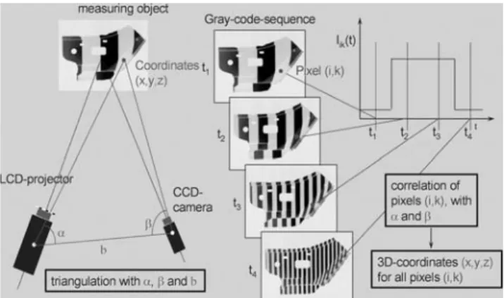
White-light projection
In stripe projection, the triangulation sensor also functions according to the basic principle of triangulation as follows: due to the known configuration of the sensor, the value Dx, measured by a diode, can be converted directly into the distance Dz of the object being measured. In the light-stripe procedure, by expanding a point of light into a line, the resulting picture can be registered by a laminar CCD sensor; the profile of the object being measured at this location can then be computed (Fig.3).
Fig. 1 Fundamental principle of triangulation: from the distance ab and the anglesα and β, the relative position of c to a and b
can be explicitly determined Fig. 3 Principle of triangulation and the spaceindividual surface points by phase shifted white light stripes (gray–time coding of code). Measurement object is a car door due to the original application (modified after Haberstok [13])
Fig. 2 Instructions for line projection. A flexible line is located at point a and a camera at point b (quoted from Vivid 910 Product Brochure; Konica Minolta Sensing Inc. Osaka Japan)
Measurement appliances
Non-contact digitizer VIVID 900/VI-900®, Minolta The scanner is 413 mm high, 213 mm wide, 271 mm deep and weighs approximately 11 kg. It runs at 100–240 V AC and functions at a wavelength of 690 nm.
Further included is the Software Package Polygon Editing Tool (PET 2.0 ®, Konica Minolta Holdings Inc., Tokyo, Japan), a lens box with three different lenses, a laser barrier and a white-balance VI-A10 cap.
There are three different, interchangeable lenses: TELE, MIDDLE and WIDE. The lens can be selected and attached according to the size and distance of the object. The closer the object is to the scanner, the greater the measurement accuracy. To reduce shadowing caused by rough-surfaced objects, the object can be positioned further away for scanning. A tabular guide of recommended measurement distances is provided by the manufacturer. The focal distance ( f ) for the TELE lens is 25 mm, for MIDDLE, f= 14 mm and for WIDE, f=8 mm. Generally one can work in a variable measurement field with a distance between the object and the camera of 0.6 and 1.2 m and a measuring time of 2.5 s 307,000 geometrical points on the z axis can be captured at a resolution of 0.008 mm.
Measurement settings vary between the fastest speed (FAST mode) and the slowest speed (FINE mode). In addition, there is an adjustable COLOUR mode. The FAST mode is appropriate for cases in which the recording speed has priority; the FINE mode, when precision is called for. Recording time is 0.3 s in the FAST mode and 2.5 s in the FINE mode. Best suited for scanning human surfaces is the
FAST mode in order to minimize movement artifacts (breathing, blinking). Once a scan is acquired, the image appears on the LC display. One obtains a polygon net which can be edited and evaluated using PET ® (PET 2.0 ®, Konica Minolta Holdings Inc., Tokyo, Japan) and all other currently available software packages (Fig.4).
Tricolite®(Steinbichler Optotechnik GmbH, Neubeuern, Germany)
The scanning set up consists of one or more LCD projectors and an associated CCD camera. Further components are a computer unit and a calibration plate for calibrating the scanner before each series of measurements. For the measurement set up, a centrally positioned LCD projector and a CCD camera are mounted, the latter at a 30° angle lateral to the central axis. Cable connections run from this moveable measurement set up to the central computer unit, which coordinates the entire measurement process. During measurement, white-light stripes are projected over the object to be measured. Furthermore, to increase accuracy, they are emitted onto the measured object in a selected stripe code (Gray code) and in phase shift (see Fig. 3). These white-light stripes are reflected back from the surface of the object and are recorded by the CCD camera. Thus, after triangulation, the 3D coordinates can be calculated for every point on the surface (s. triangulation procedure). The set up can be complemented by more projectors as well as colour-texture cameras. The system is equipped with the Comet® software (Steinbichler Optotechnik GmbH, Neu-beuern, Germany). The measuring procedure in this set up can only be initiated by the PC, which is responsible for the coordination of all the appliances involved. Raw data is obtained in the form of a 3D scatter plot, which can be evaluated using any of the currently available measurement packages (Fig.5).
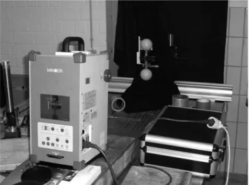
Fig. 4 Minolta set up: The casing has a handle on the top; on the front are the lens and the window out of which the laser beam is emitted. On the side are the power switch, the connecting face for the electric cable and the socket for the SCSI cable. The slit for the chip card, the integrated control panel and the LC display are located on the back, permitting easy handling directly on the appliance
Fig. 5 Tricolite set up: Configuration of LCD projector and CCD camera at a specified angle to each other
Test specimens
Both systems were tested using the quality parameters sphere-spacing error SD Δl, probing error R and flatness measurement error RE with normed test specimens of
known diameters [14]. The quality parameters are defined in detail as follows:
1. Sphere-spacing error SDΔl
The quality parameter sphere-spacing error SD serves to verify the length-measuring capability of the measuring system. Δl is determined from the difference between the measured and calibrated values of the distance between the centres of two spheres e.g. dumbbells made from steel. The surface of the spheres to be probed scatters light diffusely. 2. Probing error R
The quality parameter probing error describes the characteristic error of the optical 3D measuring system based on area scanning within a small part of the measuring volume. It is the range of the radial distance between the measured points and the best-fit sphere.
3. Flatness measurement error RE
This quality parameter means the range of the signed distances of the measured points from the best fit plane calculated according to the least-squares method. Rectan-gular parallelepipeds made from aluminium with a diffusely scattering surface are used to determine this parameter. The test plane should be approximately perpendicular to the x/y plane for all measuring positions.
Suitability with regard to health
Both systems are unobjectionable with regard to health. The white-light procedure is harmless to the eyes and calls for no special protective measures. The laser source is a class-2 laser, which requires no shielding of the eyes, but demands a proper environment for laser use without a mirror. When scanning living objects, one must take care never to look into the window from which the laser beam is emitted. No mirrors, lenses or other reflecting objects are allowed to be placed in the path of the laser beam, since there is a danger that this could influence the direction of the laser beam, provoke eye damage or even ignite flammable substances.
Results Handling
The Minolta laser scanning system has a very large measurement field, which can be covered without alter-ation. It is easy to use and the training required in order to
measure with this system is possible in minutes, even for an inexperienced layperson. Its set up is stable, showing a compact and robust construction. The mechanical connec-tion to the tripod is well solved. The lenses can be changed easily and the lens exchange is mechanically well con-structed. An advantage but also a disadvantage of this system is its calibration. The system can’t be calibrated by the user. In cases of miscalibration the system must be sent to the manufacturer. This is different with the Tricolite system which must be calibrated by the user at the beginning of every measuring series. The Tricolite system is a flexible system in the hands of a technically experienced user, which can be adapted to different tasks. Its set up is mechanically less stable and can be decalibrated more easily by mechanical effects. The depth of the measuring field is short but 3D measurements within it are very precise. The Minolta system presents a large depth of the measuring field. Therefore the triangulation angle and thus the z resolution toward the back are inevitably smaller with a consequently poorer accuracy. In both systems, the measurement time is fast (0.2 s per sight with the Tricolite and between 0.3 and 2.5 s per sight with the Minolta system). A further feature of the Minolta system is the possibility of measuring without a PC in a stand alone mode. In this set up the gained data can be stored directly on a compact flash card. As far as texture information is
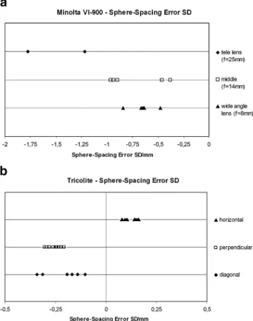
Fig. 6 a Sphere-spacing error—Minolta. b Sphere-spacing error— Tricolite
concerned the Tricolite system acquires only a gray scale texture which is not automatically mapped to the scanned surface. In contrast the Minolta system records and maps the original coloured texture information automatically. Sphere-spacing error SD
The Minolta laser scanner not only shows more deviation but all distances measured are systematically too short. The greatest deviation is given with the telephoto lens, the least deviation with the wide-angle lens (see Fig.6a). The white-light system shows less deviation (see Fig.6b).
Probing error R
The Minolta’s wide-angle lens shows major deviations (up to 4.023 mm); the results with the middle- and telephoto lenses are comparable to those obtained with the Tricolite system (Fig.7a and b).
Flatness measurement error RE
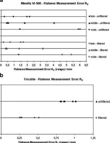
Measurement deviations with Minolta are clearly greater (maximal deviations up to 6 mm). Only slight improve-ments are made by filtering surface noise by surface smoothing algorithms, which suggests that surface smooth-ing is performed automatically by the Minolta software.
Using the Minolta system, measurements made at a large distance (small z resolution) were also considered (Fig. 8a).
Tricolite data deviate clearly less from the ideal surface— at maximally about 1 mm; the deviations can be reduced to approximately half by surface noise filtering (Fig.8b).
Discussion
The measurement accuracy of both systems lies in the sub-millimetre range. The Tricolite system measures more precisely because, with its shorter measuring-field depth, it has a shorter layer distance for smooth surfaces. This can play a role in regard to accuracy of details in complex areas like the nose, lip and ear regions. Also, when sampling objects with complex surfaces like plaster casts, the white-light method, possibly with an adapted configuration, would thus be superior. Depending on the task and problem in question, however, the appliance-dependent precision of both systems is sufficient for their medical application to the measurement of skin surfaces. Measurement errors here tend to be related to the measurement times and related movement artifacts.
Per mapping the laser system takes between 0.3 s in FAST mode and 2.5 s in FINE mode. The latter may also be suitable, depending on the problem, because of the complex Fig. 8 a Flatness measurement—Minolta. b Flatness measurement— Tricolite
surface of the face. For a complete facial image of about 270°up to four views would be required [8]. Using the laser system, this adds up to total mapping times between 0.6 and 10 s, even with a series connection of the PC-controlled scanner. The mapping times of the white-light scanner of 0.2 s also add up to 0.4–0.8 s. Since the white-light scanner is superior with regards to sampling time it is better suited for 3D Scanning of living objects because movement artifacts are avoided more easily.
Handling of the laser system is in general easier, and the appliance is more robust. It can be used without connection to a computer, thus increasing the flexibility of the system. Mobile operation with quick assembly and disassembly times as well as short, automatic calibration makes this measurement system user friendly. As far as measurement speed and accuracy are concerned, the white-light proce-dure is superior, and should thus be given preference under laboratory conditions. It must, however, be calibrated with a calibration plate before measuring. Another characteristic of this system is that its configuration can be changed. Numerous white-light cameras can be combined and a colour texture can be captured by a combination with digital cameras. The complexity of the Tricolite System requires intensive practise of this measurement technique. For well trained users, the white-light system is advanta-geous, since its configuration can be customized for various applications. It tends, however, to become decalibrated when touched, while the more robust self-calibrating laser system is much easier to handle for lay persons and for 3D scanning outside of the laboratory. Decalibration requires recalibration by the manufacturer.
Prospects
Contact-free surface capturing for medical application is well feasible with both systems. Each has its advantages and disadvantages. Which system should be given prefer-ence depends on the application in question. For 3D scanning under laboratory conditions by trained personnel, the white-light system is methodologically superior (greater precision, shorter measurement time). For 3D scanning by untrained personnel outside of the laboratory, handling of the laser scanner is more flexible and simpler. The longer measuring time can lead, however, to movement artifacts.
Acknowledgement These investigations were funded by the Suisse National Center of Competence in Research (SNF),“Computer aided and Image Guided Medical Interventions (Co-Me).”
The authors would like to thank the Steinbichler Company (Neubeuern, Germany) and the Minolta Company (Langenhagen, Germany) for technical support. The authors would further like to thank Petra Schwenzer and Virginia Dittrich for their editorial support.
References
1. Farkas, L. G., Hajnis, K., and Posnick, J. C., Anthropometric and anthroposcopic findings of the nasal and facial region in cleft patients before and after primary lip and palate repair. Cleft Palate-Craniofac. J. 30:1–12, 1993.
2. Ghoddousi, H., Edler, R., Haers, P., Wertheim, D., and Greenhill, D., Comparison of three methods of facial measurement. Int. J. Oral Maxillofac. Surg. 36:250–258, 2007.
3. Kimoto, K., and Garrett, N. R., Evaluation of a 3D digital photographic imaging system of the human face. J. Oral Rehabil. 34:201–205, 2007.
4. Gorniak, R. J. T., Kramer, E. L., Maguire Jr., G. Q., Noz, M. E., Schettino, C. J., and Zeleznik, M. P., Evaluation of a semiauto-matic 3D fusion technique applied to molecular imaging and MRI brain/frame volume data sets. J. Med. Syst. 27:141–156, 2003. 5. Bommanna Raja, K., Madheswaran, M., and Thyagarajah, K.,
Ultrasound kidney image analysis for computerized disorder identification and classification using content descriptive power spectral features. J. Med. Syst. 31:307–317, 2007.
6. Ayoub, A., Garrahy, A., Hood, C., White, J., Bock, M., Siebert, J. P., et al., Validation of a vision-based, three-dimensional facial imaging system. Cleft Palate-Craniofac. J. 40:523–529, 2003. 7. Schwenzer, K., Holberg, C., Willer, J., Mast, G., Ehrenfeld, M., 3-D
imaging of the facial surface by topometry using projected white light strips. Mund Kiefer Gesichtschir. 2(Suppl 1):130–134, 1998. 8. Kovacs, L., Zimmermann, A., Brockmann, G., Guhring, M, Baurecht, H., Papadopulos, N. A., et al., Three-dimensional recording of the human face with a 3D laser scanner. J. Plast. Reconstr. Aesthet. Surg. 59:1193–1202, 2006.
9. Weinberg, S.M., Kolar, J.C. Three-dimensional surface imaging: limitations and considerations from the anthropometric perspec-tive. J. Craniofac. Surg. 16:847–851, 2005.
10. Amann, M. C., Bosch, T., Lescure, M., Myllyla, R., Rioux, M., Laser ranging: a critical review of usual techniques for distance measurement. Opt. Eng. 40:10–19, 2001.
11. VIVID 900/VI-900 ® Konica Minolta Holdings Inc., Tokyo, Japan. Available from:http://www.minolta3d.com.
12. Tricolite® Steinbichler Optotechnik GmbH, Neubeuern, Germany. Available from:http://www.steinbichler.com.
13. Haberstok, C., Die Holographische Modalanalyse. Thesis in Applied Mechanics, Technical University, Munich, 2005. 14. VDI/VDE-Norm. 2002 August.