Publisher’s version / Version de l'éditeur:
ASHRAE Journal, 14, 12, pp. 54-56, 1973-01-01
READ THESE TERMS AND CONDITIONS CAREFULLY BEFORE USING THIS WEBSITE. https://nrc-publications.canada.ca/eng/copyright
Vous avez des questions? Nous pouvons vous aider. Pour communiquer directement avec un auteur, consultez la
première page de la revue dans laquelle son article a été publié afin de trouver ses coordonnées. Si vous n’arrivez pas à les repérer, communiquez avec nous à [email protected].
Questions? Contact the NRC Publications Archive team at
[email protected]. If you wish to email the authors directly, please see the first page of the publication for their contact information.
NRC Publications Archive
Archives des publications du CNRC
This publication could be one of several versions: author’s original, accepted manuscript or the publisher’s version. / La version de cette publication peut être l’une des suivantes : la version prépublication de l’auteur, la version acceptée du manuscrit ou la version de l’éditeur.
Access and use of this website and the material on it are subject to the Terms and Conditions set forth at
Transfer function method of calculating cooling loads, heat extraction
and space temperature
Mitalas, G. P.
https://publications-cnrc.canada.ca/fra/droits
L’accès à ce site Web et l’utilisation de son contenu sont assujettis aux conditions présentées dans le site LISEZ CES CONDITIONS ATTENTIVEMENT AVANT D’UTILISER CE SITE WEB.
NRC Publications Record / Notice d'Archives des publications de CNRC:
https://nrc-publications.canada.ca/eng/view/object/?id=bd4bf2f8-f755-4037-a6ef-4b14ec46cad7 https://publications-cnrc.canada.ca/fra/voir/objet/?id=bd4bf2f8-f755-4037-a6ef-4b14ec46cad7
NATIONAL
CONSEIL NATl
Price 10 cents
Transfer Function Method of Calculating
Cooling Loads, Heat Extraction And
Space Temperature
P%W by Gintas P. Mitalas Reprinted from ASHRAE JOURNAL Vol. 14, No. 12, December 1972p. 54-56
By permission of the American Society of Heating, Refrigerating and Air-Conditioning Engineers, Inc.
Technical Paper No. 383
of the
Division of Building Research
OTTAWA January 1973
LA METHODE DE FONCTION DE TRANSFERT ET LE CALCUL DE L'EFFORT DE REFROIDISSEMENT, DE
L'ENLEVEMENT DE LA CHALEUR ET DE LA TEMPERATURE AMBIANTE
SOMMAI RE
Une nouvelle methode de calcul de I'effort de refroidissement, l a methode de fonction de transfert, a kt6 introduite dans I'Bdition de 1972 du Handbook of Funda~nentals. Le present article est une breve etude des modalitis de calcul de cette methode, mais il s'agit surtout de montrer que celleci possede un champ d'applica- tion plus vaste que 1"'ancienne" methode. On compare 1'"ancienne" methode et la methode elargie quant au calcul des profils d'effort de refroidissement. Les rksultats d'un calcul- Cchantillon montrent graphiquement les applications elargies de cette methode relativement
i
un programme d'exploitation variable, au calcul de I'enlevement de la chaleur a une tempera- ture ambiante variable de I'air et aux caracteristiques d1en18ve- rnent de la chaleur d'une borne de conditionnement de I'air ( yTransfer Function Method
of
Calculating
Cooling Loads,
Heat Extraction
&
Space
Temperature
GINTAS P. MITALAS Member ASHRAE
A new cooling load calculation procedure, the transfer func- The ASHRAE Task Group on Energy ~ e q u i r e m e n t s after
tion method, has been incorporated rn the 1972 ASHRAE five year's work, developed a computer-oriented method
HANDBOOK OF FUNDAMENTALS, 7his presents a that has now been incorporated in the 1972 AsHRAE HAND-
short discussion of the calculation procedure based on the BOOK OF FUNDAMENTALS. This new method has been desk-
transfer f u n c t i o n method, and demonsfrates ,he extended nated as the transfer function method because it utilizes the
capability o f this new, computer-orlenfed, method. transfer function concept to relate cooling load to heat
gain, and heat extraction rate to cooling load and room air temperature.
A transfer function is a set of coefficients that relate
T
HE growing concern about e n e r g consumption and an output function at some Specific time to the value of one the consequent urge to analyze more thoroughly the o r more driving functions at that tinle and to previous values design of alternative systems for the heating and cooling of of both the input and output functions- For example, a buildings has led to a demand for improved methods of component of cooling load a t time T, QT, can be related topredicting the performance of air-conditioning systems. the corresponding component of the heat gain q T by an expression of the form
7 ,
I I I I I I I 1 I I I I 4 0 QI = v0qe.r
+
v l q e , ~ - A+
V2qs.r-2A f. .
= wlQr-,i
-
w ~ Q , - z A-
w3Ir-3*-
-
-
.
b - /-\
-
l o Values of the v,, V,. .
and the w,,w,
.
,.
coefficientsS O L - A I R T C M P C R A T U R I
'
'\ depend on heat storage characteristics of the building and onA1 OUlSlDE SUBFACE
-
s -.
& the nature of the particular heat gain component. Table I
5
(Table 44 in Chapter 22) lists values of these coefficients for3 4 -
-
various components of heat gain and for three classes ofbuilding, viz., heavy, medium and light-weight construction.
2 2 - The new computer-oriented procedure is an extension
IPANSFER F U N C I I O N
'.'
-...
IfXAMPLf 16 )Q
...
and development of the old familiar methods. It uses the2
-
"...
-
standard approach to calculate most of the components ofheat gain: heat gain from lights is the power supplied to the
I
-
2--
<
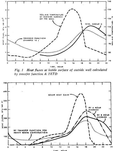
lights, etc. The heat gain through opaque wall and roof ele-ments is the only exception in that it is not calculated using
1
1
],
1
,
j0
,,
Total Equivalent Temperature Difference (TETD), butT ~ M C , H O U R rather by using the appropriate sol-air temperature data
Fig. I Heat fluxes at inside surface of outside wall calc~ilated and combining them with a wall heat transfer function, i.e.,
by rrmrsfer f~cnctiotz & T E T D this component of heat gain is found by using a transfer
function approach. Transfer function coefficients for many
700
1 I I I 1 I I I I I I widely used types of walls and roofs are listed in Tables 39 and 40 of the 1972 HANDBOOK.
boo
-
-
The heat fluxes at the inside surface of the outsideS O L A l HEAT G A I N
-4
'\ wall, given in Fig. 1, show the results of the two calculationSOU
-
/ \-
methods i.e., transfer function and TETD. The heat fluxes&
-
1 1 calculated by the two methods agree reasonably well.x
3 4 0 C - / 1 LY 6 X O U l
-
The transfer function approach to converting a com-ponent of heat gain into the associated component of cool-
i
2,oe
-
ing load is, in principle, very similar to the time-averagingL.
-
approach that was recommended in the 1967 ASHRAE5
I Z O C
-
HANDBOOK. The new technique differs in that it applies aIV T ~ A N S F ~ I F U N C ~ I O N F O R different weighting factor to each of the preceding values of
I oc heat gain rather than giving exactly the same weight to sev-
eral values of heat gain. The calculated values of cooling
1 V,,L
-1
load are more accurate when the new factors are used.0 2 4 b 8 10 1 1 14 16 I 8 20 12 I 4
I I M t , HOUt
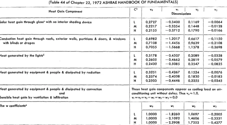
Fig. 2 Coolitzg load profiles calcitlated by transfer function & G.P. Mitalas is Assistant Research Oficer, National Research
nvet aging methods Council, Div. o f Building Research, Ottawa, Ont., Canada.
Table I. Coefficients of Room Transfer Functionsa
(Table 44 of Chapter 22, 1972 ASHRAE HANDBOOK OF FUNDAMENTALS)
--.
-Heat Gain Component V I
I
v2Dimensionless
- - -. - -. ...
Solar heat gain through glassC with no interior shading device L 0.2727 -0.3400
M 0.2217 -0.3354
H 0.2155 -0.3712
Conduction heat gain through roofs, exterior walls, partitions & doors, & windows L 0.6982 - 1.2017
with blinds or drapes M 0.7108 - 1.4456
H 0.7055 -1.5668
Heat generated b y the lightsd
Heat generated by equipment & people & dissipated b y radiation
Heat generated b y equipment & people & dissipated by convection
and
Sensible heat gain b y ventilation 8 infiltration
These heat gain components appear os cooling load on air-
conditioning unit without delay. Thus v,= 1 .O.
~ ~ = ~ ~ = ~ ~ = w ~ = w ) = w ~ = O . O The w coefficientso
&'The coefficients o f the transfer function given in this table were calculated b y procedures outlined in Ref. 44.These coefficients are applicable for the case where all the heat gain energy appears eventually or cooling load.The computer program used for these calculations was developed ot the National Research Council of Canada, Division of Building Research.
The letters L, M and H denote the following room construction features used to calculate the above room transfer functions:
L = Light construction: frome exterior wall, 2 in. concrete floor slob. approximotely 3 0 I b of material per sq ft of floor area.
M = Medium construction: 4 in. concrete e ~ t e r i o r wall, 4 in. conmete Roor slab, approximately 70 Ib o f building material per rq. ft. of floor orea.
H = Heavy construction: 6 in. concrete exterior wall, 6 in. concrete floor slab, approximotely 1 3 0 I b of building materials per sq f t of floor area. For all carer, the room was assumed t o be furnished.
The coefficients of the transfer function that relote room cooling load to the solar heot gain through gloss depend on where the solar energy is absorbed. I f the window is shoded b y an inside blind or curtain, most of the solar energy is absorbed b y the shade and is tronsferred to the room b y convection and long-wove radiation in about the same proportion as the heat goin through wells and raofs.Thur the heat gain through windows with inside shading devices can b e combined with the wall and roof heat gain and converted to cooling load using the transfer function for heat gain through walls.
If theventilating air i s exhausted through the space above the ceiling, it remover some of the heat from the lights before it enters the room. This heat ir o load on the air-conditioning plant if the air is recirculated, even lhough i t is not part of the heat gain o f the room. The percent of heat gain appearing in the room depends on the type of lighting fixture, its mounting, and the exhaust air flow.
The wi coefficients (of the denominator) apply to all components of input except for the convection prrrt of heot gain from and equipment.
Table II. Normalized Coefficients of Room Air Transfer FunctionRJ' (Table 46 of Chapter 22,1972 ASHRAE HANDBOOK OF FUNDAMENTALS)
---pp
Conshuction
/
I
I
"*Btu/(hr) (sq ft) ( F deg) dimensionless i = O
---
--.-I
Light
/
1.731
-3.501
2.221
-0.45/
1.00001
-
1.82601
1.06971
-0.20051
0.0432Medium -4.22
1
3.08 - 0.74 -2.10921
1.4606 -C.33311
0.0183Heavy
/
::::
I
-4.55I
3.611
-0.951
1.0000 -2.29081
1.7252I
-0.4277,
0.0067-
a A simplifled procedure for calculating room air transfer function coefficients i s given in Ref. 45.
The g* coefficients given in this table ore for a room with zero heat conductonce to surrounding spaces and are normalized to unit floor oreo. To get the g coefficients for a room with a total conductance K between room air and surroundings, ventilation rate V, and infiltration rate VI, it i s necessary to multiply eoch g;* value by room floor oreo and then o d d lKS(V,+YI,)1.08lZi-03pi to the resulting govolue (whereV,andVl,areincfm).
Note that go value changer with the changes o f V, and VI, values.
Daily profiles of cooling load calculated using transfer function and averaging methods as well as the heat gain used for these calculations are shown in Fig. 2. These .'
curves show that the averaging method gives a substantially different cooling load profile as compared to the profile cal- culated by the transfer function method.
The main advantage of the new procedure, however, is that it takes the calculation a step beyond the determina- tion of cooling load and evalwates the rate at which heat will be removed from a space and the temperature of the space when a specific size and type of cooling unit is used. This phase of the analysis also allows the designer to evalu- ate the effects of different schedules of operation. This was
not possible with the old methods. By enabling the designer to evaluate the deviations of room air temperature from the nominal design value it is possible for him to exploit the finite width of the comfort zone and select equipment that can maintain conditions within the zone, albeit not always at the center of the zone.
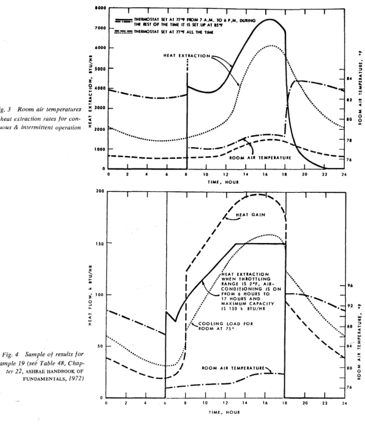
Results of a calculation are given in Fig. 3 to illustrate the flexibility of this method. In one case, room air temper- ature control is set at 77 F all the time; in the other case the thermostat set point is at 77 F only during the occu- pancy period; the rest of the time it is set at 85 F. The transfer function coefficients used for this calculation are given in Table I1 (Table 46 in Chapter 22).
Fig. 3 Roorn air temperatrcres
& herif rxfractiot~ rates for con- rir~ituirs & i?itertnittet~f ol~eraliot~
0 1 4 b B 10 I 2 14 I6 18 2 0 11 1 4
T I M E , HOUR
Fig. 4 Sample of results f o r E.\-ample 19 (se6 Table 48, Chap- ter 2 2 , ASHRAE HANDBOOK OF
FUNDAMENTALS, 1972)
0 2 4 6 8 10 1 2 4 16 18 2 0 22 2 4
TIME, HOUR
Example 19 (from Chapter 22) and the curves in Fig. 4 indicate the sort of result that can be obtained using the new methods. It is interesting to note that in this example the peak heat gain is 197 MBh,* but that the peak cooling load is only 158 MBh. Furthermore, if the cooling unit has a maximum capability of 150 kBtu/hr, it wil be able to keep the room temperature between 75.4 and 77 F. Results also show the consequences of using different throttling ranges for the control system and the conditions that would occur if the cooling system were shut down during the night. Attention is drawn to this example because it illus- trates the kind of analysis that the new method makes pos- sible. The actual results are of little intrinsic interest as it is
not intended to imply that the same ratio of heat extraction to heat gain would obtain'for other situations. Every case should be examined on its own.
CONCLUSION
This is the first time that the transfer function method has been presented in this form for practical design calculation. It can be anticipated, therefore, that some minor difficulties may arise in its application. It is hoped that difficulties, if there are any, will not deter the majority of ASHRAE HAND-
BOOK users from trying the method.
:"000's Btuh.
This publication is being distributed by the Division of Building Research of the National Research Coun- cil of Canada. I t should not be reproduced in whole or in part without permission of the original publisher. The Division would be glad t o be of assistance in obtaining such permission.
Publications o f the Division may be obtained by mailing the appropriate remittance (a Bank, Express, or Post Office Money Order, or a cheque, made payable t o the Receiver General of Canada, credit NRC) t o the National Research Council of Canada, Ottawa. K I A 0R6. Stamps are not acceptable. A list o f all publications of the Division is available and may be obtained from the Publications Section, Division o f Building Research, National Research Council of Canada, Ottawa. K I A OR6.