HAL Id: hal-02273039
https://hal.archives-ouvertes.fr/hal-02273039
Submitted on 4 Nov 2019
HAL is a multi-disciplinary open access
archive for the deposit and dissemination of
sci-entific research documents, whether they are
pub-lished or not. The documents may come from
teaching and research institutions in France or
abroad, or from public or private research centers.
L’archive ouverte pluridisciplinaire HAL, est
destinée au dépôt et à la diffusion de documents
scientifiques de niveau recherche, publiés ou non,
émanant des établissements d’enseignement et de
recherche français ou étrangers, des laboratoires
publics ou privés.
Desertscape Simulation
Axel Paris, Adrien Peytavie, Eric Guérin, Oscar Argudo, Eric Galin
To cite this version:
Axel Paris, Adrien Peytavie, Eric Guérin, Oscar Argudo, Eric Galin. Desertscape Simulation.
Com-puter Graphics Forum, Wiley, 2020, 38 (7), pp.47-55. �hal-02273039�
Desertscape Simulation
A. Paris1 , A. Peytavie1 , E. Guérin1 , O. Argudo1 , and E. Galin1
1CNRS, Université de Lyon, LIRIS, France
Abstract
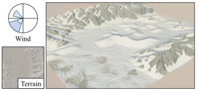
We present an interactive aeolian simulation to author hot desert scenery. Wind is an important erosion agent in deserts which, despite its importance, has been neglected in computer graphics. Our framework overcomes this and allows generating a variety of sand dunes, including barchans, longitudinal and anchored dunes, and simulates abrasion which erodes bedrock and sculpts complex landforms. Given an input time varying high altitude wind field, we compute the wind field at the surface of the terrain according to the relief, and simulate the transport of sand blown by the wind. The user can interactively model complex desert landscapes, and control their evolution throughout time either by using a variety of interactive brushes or by prescribing events along a user-defined time-line.
Keywords: Procedural modeling, desert, sand dune simulation, aeolian erosion
1. Introduction
Terrains are a visually salient feature in large-scale virtual worlds and are used in a wide range of computer graphics applications. The variety and the complexity of landforms come from the many ge-omorphological processes at different time and spatial scales such as plate tectonics, glaciation, erosion or even the presence of vege-tation, which shape the relief.
Hydraulic erosion attracted the most attention in the computer graphics community, focusing on the creation of Alpine mountain ranges with specific features resulting from the action of water, such as dendritic river and ridge networks, eroded mountain ranges with sedimentary valleys. In contrast, the impact of wind erosion over terrains in hot and arid regions has seldom been addressed de-spite their significant earth coverage and scenic visual aspect.
Wind is an important erosion agent in hot deserts, where annual rainfall is low. In particular, hot desert landscapes are character-ized by particular landforms modeled by the action of wind such as dunes of different shapes and sizes, eroded table mountains, and bedrocks sculpted by the abrasion of sand blown by the wind.
In this paper, we present an original framework inspired by the aeolian processes described in geomorphology. Our method effi-ciently simulates different sand grain movements including salta-tion, reptasalta-tion, and avalanching which take place in the generation of many desert features such as sand dunes created by the accumu-lation of sand, nabkha protecting vegetation blocking the transport of sand, and yardangs created by abrasion of the bedrock (Figure1). We model the terrain using a layered data-structure combin-ing bedrock, sand and vegetation density, and use stochastic rules to simulate how the sand transported by the wind interacts with
Terrain Wind
Figure 1: Example of a desert landscape modeled with our simu-lation. The user defined a wind rose, added local swirls, and finally placed sand at the center of the scene. Our model automatically created a mega barchan and a star-shaped dune. The turbulence also created asymmetric transverse dunes as well as a linear dune.
bedrock and vegetation. Given a user-defined heightfield and time varying high altitude wind field, our method automatically com-putes wind at the surface of the terrain taking into account the re-lief, simulates the abrasion of bedrock by the sand carried by the wind, and computes the formation of dunes. Our simulation runs at interactive rates and provides multiple levels of control: at any time during the simulation the user may add or remove sand, change the wind direction or modify the vegetation density and directly see the evolution of the system.
The main contributions outlined in this paper include: 1) a proce-dural model for approximating the wind flow over the relief of the terrain, 2) for the first time in computer graphics, an interactive aeo-lian erosion simulation derived from algorithms in geomorphology, combining a set of stochastic sand transportation rules operating on
A. Paris et al. / Desertscape Simulation a layered terrain model, 3) a controllable wind-based approach for
authoring desert landscapes, adapting wind to the terrain with a multi-scale warping and providing a variety of interactive control tools to the user. To our knowledge, this work is the first to perform an interactive approximation of the wind flow and sand transport at the surface of the terrain as a basis for generating synthetic desert landscapes.
2. Related work
Here we review erosion simulation methods applied to terrain modeling and synthesis and focus on approaches that specifi-cally address the generation of desert scenery. We refer the reader to [GGP∗19] for a complete review of terrain modeling techniques, including procedural generation, simulation and example-based synthesis. In geomorphology, we refer to [PT09,Lan95,LBS13] for a more complete overview of the formation of sand dunes, aeo-lian erosion and more generally to desert landscapes.
2.1. Erosion simulations
Erosion simulations usually approximate the geological evolution of terrain through iterations of hydraulic ero-sion [MKM89,RPP93], subsurface tectonics [CBC∗16,CCB∗18], or a combination of effects [CGG∗17]. Layered material strata are encoded as a cell-based grid of layered stacks, with different thicknesses and material properties for the layers of each cell-specific stack. Hydraulic erosion is often combined with thermal erosion [MKM89,RPP93] or hill slope erosion [CGG∗17] which is the action of material breaking and falling under the action of temperature changes. Although hydraulic erosion simulation approaches capture a vast variety of phenomena, they are difficult to control and computationally intensive, even with graphics hardware acceleration [ŠBBK08].
While the majority of procedural approaches focused on moun-tainous landforms, modeling deserts with sand dunes received little attention from the computer graphics community. [GGP∗15] pro-posed to model specific landforms, including transverse dunes, by combining parameterized elevation primitives organized in a con-struction tree. The model requires a fine tuning of the noise func-tions as well as intensive editing to locate the primitives in the scene.
Onoue [ON00] used the saltation equation and adapted simula-tions from physics into a procedural model to generate sand ripples. This method was extended by [BR04] to include the collision of sand with obstacles. Those methods successfully model sand rip-ples and small bumps, but fail to generate the vast majority of sand dunes such as barchan or star dunes. Furthermore, no interaction between layers (vegetation, bedrock and sand) is specified, despite playing a key role in the formation of desert features.
An approximation of the effects of wind erosion on rocks by us-ing the local curvature and accessibility of the surface was proposed
in [BFO∗07,JFBB10]. This approach allows the creation of
Gob-lin structures. While the method can reproduce a variety of small scale features, it does not lend itself for representing large phenom-ena such as yardangs, which range from a few meters to several kilometers.
2.2. Granular material simulations
Granular material simulations often use particles to represent the sand grains and compute their movement [ZB05,BYJM05]. These approaches can represent the dynamics of complex phenomena such as stabilization of sand particles. They can model interactions with fluids and rigid or deformable bodies [YJL∗16]. Recent work focused on preserving the exact coupling between normal and tan-gential stresses using the material point method [DBD16]. While these approaches successfully reproduce the behavior of sand with fluids, deformable bodies and rigid obstacles, they are limited to small areas (up to a few square meters) and therefore do not scale to desertscapes spatial ranges.
2.3. Sand dune simulations
Stochastic models [Wer95] have been proposed in geomorphology for simulating the transportation of sand by the wind and the for-mation of different types of dunes. Barchan and transverse dunes can be simulated efficiently with a uniform and unidirectional wind flow under different sand supply conditions. This model was im-proved by approximating the effect of wind acceleration on the windward side of dunes [MCGBW00], which produces more asym-metric dunes and allows to better simulate their movement through-out time. The impact of vegetation on the shaping of sand dunes was studied in [Baa02] by introducing an additional layer repre-senting vegetation density.
Simulating more complex dunes such as star-shaped or network dunes remains challenging: the sand accumulation results from the complex interaction between irregular wind fields and the ter-rain, and capturing the dynamics of winds with vorticity and ed-dies over a constantly evolving terrain remains a computationally intensive problem. Therefore, although changes in the wind di-rection and speed strongly influence the type and shape of dune formations, most existing techniques rely on 2D wind flow ap-proximations and avoid computationally intensive wind simulation. Narteau et al. [NZRC09] proposed a 3D wind model to represent complex effects such as transport, gravity and diffusion. This model was extended in [ZNRCdP12] to reproduce star dunes, which are complex to create by simulations.
Intensive fluid simulations are beyond the scope of our target in-teractive application. Instead, we propose a phenomenological ap-proach for computing the wind at the surface of the terrain, tak-ing into account the relief at different scales. Aeolian erosion is also known to be responsible for the formation of yardangs created by abrasion. Despite several field studies and wind tunnel experi-ments [WG84], we are not aware of any numerical model capable of creating yardangs.
3. Overview
Deserts are regions with low water supply. Depending on the amount of precipitation, they can be classified as hyper-arid, arid or semi-arid. Hyper-arid and arid deserts, which receive less than 250mm of rainfall per year, represent almost 25% of earth surface and have been extensively studied in geomorphology [Hug03].
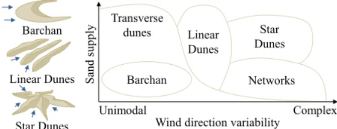
Geomorphological phenomena Deserts are composed of differ-ent landforms created by aeolian processes: wind eroding, trans-porting and depositing materials. Wind erosion effects include de-flation (removal of loose, fine-grained particles due to the turbulent action of the wind) and abrasion (wearing down of the bedrock by the grinding action of sand particles carried by the wind). The trans-port and accumulation of the sand particles lead to the formation of sand dunes. Barchan Sa nd s uppl y
Wind direction variability Unimodal Transverse dunes Complex Star Dunes Networks Linear Dunes Star Dunes Barchan Linear Dunes
Figure 2: Different types of dunes, in relation to the variability of wind direction and sand supply.
The complexity and variability of wind direction plays an impor-tant part in the formation of different dunes (Figure2): transverse dunes and barchans are formed from unimodal winds, i.e. wind blowing from one major direction, whereas star dunes and dune networks featuring complicated structures and patterns are known to be shaped by complex wind regimes, with local turbulences and vortices, even though the exact process remains an active field of research. The relief of the terrain and the presence of vegetation also influence sand transport, and thus the different types of dunes formed [LBS13]. Anchored dunes such as nabkha are those created under the influence of vegetation [Baa02], as opposed to free dunes such as transverse, barchan, and star-shaped.
Layered Model
High altitude wind field a(t)
Bedrock B Sand S Vegetation V
Sand movement:
saltation, reptation, avalanching
Aeolian erosion and
abrasion Wind surface computation w(p, t) Terrain and vegetation editing Sim ulatio n Cont rol Simulation with resistance ρ
Figure 3: Synthetic overview of the simulation.
Terrain Representation Our layered terrain model, denoted as T , is a discrete regular grid of size n × n cells. It is combined with a multi-layer ordered data-structure to represent different ter-rain materials and plant density in every cell (Figure3). The sand S layer represents the material thicknesses on top of a bedrock layer B, which defines the base elevation. Plants are represented using a generic vegetation density layer V which takes values in [0, 1] and represents vegetation cover. The resistance of the bedrock ρ : R2→ [0, 1] defines the resistance to erosion; regions with a high
resistance to erosion (ρ = 1.0) are eroded slower than low resis-tance ones (ρ = 0.0).
Wind and sand transport simulation At the heart of our method is a sand transport algorithm based on the computation of the wind at the surface of the terrain which takes into account the relief. At every time step, we compute the evolution of terrain model T (t + ∆t) according to the wind conditions w(p,t). Figure3 presents an overview of our simulation. Given an initial input lay-ered representation of the terrain and a high altitude wind field a, we compute a time varying wind field w over the surface of the ter-rain (Section4), which is used to compute the movement of sand.
The transport and collision of sand with the relief and vegeta-tion form different types of dunes (Secvegeta-tion5.1), and at the same time erode the terrain through abrasion (Section5.2). The vegeta-tion layer plays a part in the formavegeta-tion of anchored dunes such as nabkha, which only form around plants, and greatly influences the shape of the dunes by preventing sand from being blown by the wind. Since the simulation is performed at a 1 − 10 m range per cell, we finally add procedural details to the sand layer to account for small bumps around plants and sand ripples (Section6). Sim-ilarly to [Wer95], our simulation is performed on a toric domain: the sand moved beyond one bound is transported to the opposite bound, which preserves the overall volume of sand during the sim-ulation. Note that the bedrock layer has to be tileable so as to avoid artefacts caused by different elevations on opposite sides.
Control The high altitude wind regime is defined by a wind rose that prescribes the wind direction and speed distribution through-out time. At any time in the simulation, the user can change the high altitude wind field a and edit the wind field at the surface of the terrain by adding local procedural wind primitives such as ed-dies. Moreover, throughout the simulation, it is possible to add or remove sand, sculpt the underlying bedrock, and change the density of vegetation (see accompanying video).
4. Wind surface computation
We define the wind field over the surface of the terrain w : R3→ R2
by constructing a high-altitude wind field, denoted as a and com-puted from a wind distribution (wind rose), and then warping it at different scales according to the relief T . We define the wind field w as:
w(p,t) = σ(p,t) ω ◦ a(t) + u(p,t)
The function ω : R2→ R2 denotes a multi-scale warping taking
Surface wind field w(p,t) Sh ad owin g High altitude wind field a(t)
W ar pin g Wind shadow field σ(p,t) Wind rose
A. Paris et al. / Desertscape Simulation into account the relief of the terrain at different scales which
de-forms the wind field (Figure4). The function σ : R3→ [0, 1] scales the speed by computing the shadowing effects that are generated by small scale elevation features such as sand dunes and small steep cliffs. Eventually, u : R3→ R2 is a user control local wind field perturbation which allows the user to edit the wind field w locally, for instance by adding swirls or turbulence. The final resolution of the wind field w is n × n, which is the same as the other sand and bedrock layers of our simulation.
4.1. High-altitude wind field N W E S Speed (m/s) 0 5 10 15
Figure 5: Wind rose.
The high altitude wind field a : R → R2is approximated as a time varying wind of uniform direction and speed over the terrain, since we focused on relatively small domains (up to 10 × 10 km2). In our framework, users can either specify the variation of direc-tion and speed throughout time, or rely on generic wind regime models. Wind regimes are specified by a wind rose that represents the distributions of wind speeds and directions (Figure5). The wind rose diagram also features the wind speed ranges.
4.2. Warping
The high altitude wind field a is then warped according to the re-lief of the terrain at different scales. Therefore, we compute the smoothed elevation function of the terrain at different resolutions: let R a smoothing radius, we define eTi= T ~ gRias a convolution between the terrain T and the Gaussian kernel of radius Ri.
We first account for Venturi effects, which accelerate wind at higher altitudes, according to the base elevation:
v(p,t) = a(t) (1 + kWT (p))
The term kWis a scaling parameter, set to 5 × 10⁻³in our model.
While this linear equation only approximates a more physically complex phenomenon, it lends itself for our interactive purposes as it is efficient and easily controllable.
We then change the direction of the wind according to the gra-dient of the surface of the terrain at multiple scales. We define the wind at surface as a weighted sum:
i=n
∑
i=0
ciωi◦ v(p,t)
The term ωi◦ v denotes the warping of v at scale i weighted by
coefficient ci. The warping operator is in turn defined as:
ωi◦ v(p,t) = (1 − α) v(p,t) + α kT i∇ eTi⊥(p) α = k∇ eTi(p)k
The term kT i is a deviation coefficient set by the user, and α the
normalized slope of the smoothed terrain. ∇ eTi⊥(p) denotes the
or-thogonal vector to the terrain gradient in the direction of v, thus v · ∇ eTi⊥(p) > 0. In our experiments, we used n = 2: convolution radii were set to 200 m and 50 m, with corresponding weights 0.8 and 0.2, and deviation coefficients of 30.0 and 5.0 respectively.
This allows us to redirect the wind with respect to mountains and smaller cliffs or mesas.
4.3. Wind shadowing
Wind shadowing occurs in the lee side of terrain relief or vege-tation, i.e. those areas where wind flow has been slowed down sufficiently to suppress any further transport of sand. This com-plex phenomenon is fundamental in the formation of all sand dunes [Baa02].
In our simulation, we conform to experiments in geo-morphology demonstrating that wind shadowing takes place under a 15 degree accessibility angle. Therefore, wind
Shadowed cell
RS
p
Windw
Figure 6: Shadowing.
shadowing at a point p is approx-imated using a dampening function σ(p), computed as follows. Starting from p, we march in the opposite di-rection of w(p,t) and check intersec-tion with the terrain (Figure 6). The maximum marching distance is a con-trol radius Rsset to 10 m in our
simu-lation, and the marching step is set to 0.5 m. We keep the point q with the maximum elevation difference regarding p, and compute the angle α as:
tan α = (T (p) − T (q))/(kp − qk)
We finally compute shadowing as the linear interpolation between 10 and 15 degree from the angle α.
Note that the computation of w is performed at every step of the simulation in order to account for the time varying high alti-tude wind field a, as well as the constant movement of sand dunes, which leads to different warping and shadowing effects as the land-scape evolves. While this update is computationally intensive, our multi-scale approach generates realistic sand transport effects by weighting obstacles accordingly to their size: a small hill does not have the same impact on the wind direction as a mountain peak.
4.4. Control
The user-controlled perturbation field u : R3→ R2 is constructed
by combining time varying procedural wind primitives as pre-sented in [BHN07]. This approach provides a good user-control over the simulation process and guarantees that u(p,t) should be divergence-free. The perturbation field provides the user with local control and enables her to add eddies or turbulences at prescribed locations, which are important for some specific phenomena such as asymmetric transverse or star dunes (Section7).
5. Sand simulation
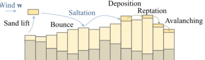
Our sand transport model involves three different sand move-ments: saltation, reptation and avalanching which are modelled as stochastic processes (Figure7). The fundamental sand transport process leading to the formation of dunes is saltation (Section5.1). Depending on its strength, wind can lift and carry sand along
its direction, bouncing possibly multiple times before being de-posited at some other location. In turn, these bounces and depo-sitions produced by saltation can trigger reptation, also referred to as creep, which is the movement of sand grains to adjacent posi-tions upon impact by other sand grains. Finally, when the deposited sand creates a local slope greater than the angle of repose threshold, avalanchingevents are triggered. Note that saltation moves sand in the direction of the wind, whereas reptation and avalanching may transport it in different directions.
Wind w
Sand lift Bounce
Reptation Deposition Saltation
Avalanching
Figure 7: Processes involved in sand transport: saltation lifts sand in the air and transports it over a few meters, possibly with multiple bounces. Deposition eventually occurs based on stochastic rules in-volving the presence of sand, vegetation and wind shadowing. Rep-tation is triggered by the deposition of sand at the end of salRep-tation.
Wind also erodes the surface of the terrain by deflation and abra-sionprocesses. In our model, aeolian abrasion occurs whenever a small amount of sand blown by the wind is transported over bare bedrock (Section5.2).
5.1. Sand transport
For every cell C of the grid, we successively trigger a series of events according to the surface wind w(p) at the location of the cell: starting with saltation, a small fixed amount of sand, often re-ferred to as slab in geomorphology [Wer95], is lifted and moved over the grid by successive saltation steps or bounces, triggering in turn reptation events until sand is eventually deposited back to the ground, which might trigger avalanching events.
Saltation We approximate saltation as a stochastic event on a given cell C in three steps. First, lifting removes a small amount of sand εS. Then, wind transports εSto a target cell denoted as N
located at q = p + d ◦ w(p,t) where d denotes the saltation distance function of the wind. In our model, the saltation distance is linear to the intensity of the wind kw(p,t)k and transports the sand along its direction. When this sand slab hits the ground, it can either bounce or be deposited on the ground according to a probability β. This probability depends on wind shadowing σ(q), the presence of sand S(q,t) and the vegetation density V(q,t) of the target cell N :
β = σ(q) + fS(S(q,t)) + fV(V(q,t))
Note that we clamp the value of β in [0, 1]. The transfer functions fS and fV are defined as follows. Following [Wer95], we model
fSas the step function fS(0) = 0.4 and fS(x) = 0.6 for x > 0. The
action of saltation is more intense in those places where vegetation is sparser since sand grains are unconsolidated, therefore we used a linear decay: fV(x) = 1 − x for the vegetation density term. In our
model, the value of εSis set to 0.1.
Steeper slopes α= 45° Windw Collision Lifting dampening α= 30° No lifting Lifting
Figure 8: Vegetation limits sand particles lifting during saltation, decreases the probability of bouncing, and prevents avalanching and reptation.
Reptation is a process whereby sand grains collide with other grains during bounces in saltation, prompting them to move in the slope direction. Reptation is the second key process in sand trans-port, after saltation. It is also, with avalanching, a process where sand grains can move laterally to the wind direction.
We model reptation as a stochastic event that is triggered by the sand slabs bounces and depositions during saltation transport. In reptation movements, a small amount of sand εR is displaced to
neighboring positions depending on the slope.
In our model, we transport sand to the n steepest neighbors of the current cell, and distribute the quantity εR(set to 0.1 in our
sim-ulation) to each neighbour proportionally to their steepness, so that the steepest neighbors receive more sand from reptation. We empir-ically found that n = 2 was enough to account for the chaotic nature of this phenomenon; adding more neighbors can lead to oscillations and visual artefacts.
Vegetation also influences reptation as it shields and retains sand from being blown by the wind. In our implementation, the proba-bility βRof a reptation event is defined as: βR= 1 − V.
Unstable cell C
s(p)>tan α
Sliding
Figure 9: Sliding.
Avalanching occurs when the local slope s(p) of the sand is greater than a given threshold defined by the repose angle: s(p) > tan α (Figure9). Sand slides in the direction of the steep-est slope only, making avalanching a deterministic process as opposed to saltation and reptation. The avalanch-ing process participates to the forma-tion of climbing dunes and talus on the leeward side of steep cliffs (see Figure10). When saltation has transported sand from one cell to another, we check stabil-ity on both cells and trigger sand slides if necessary. We model this process in the same way as the granular material stabilization process described in [CGG∗17] by checking stabilization on a per-cell basis, propagating material to neighbouring per-cells and triggering avalanching events to those cells.
Vegetation prevents avalanching by retaining sand (Figure8). In our model, vegetation density changes the angle of repose threshold value: we linearly interpolate between α = 30◦for bare sand and α = 45◦for sand covered by vegetation (V = 1).
Parameters Existing models in geomorphology are often dimen-sionless, which allows them to reproduce different phenomena
oc-A. Paris et al. / Desertscape Simulation
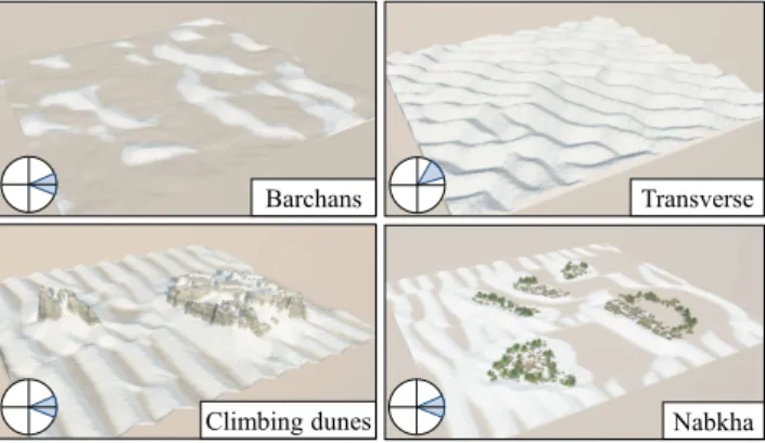
Barchans Transverse
Climbing dunes Nabkha
Figure 10: Our method generates different types of dunes: free dunes such as barchan and transverse dunes (top row) form with uniform wind conditions; anchored dunes are influenced by their environment: climbing dunes appear at the bottom of small cliffs, and nabkha are created near vegetation.
curring at different scales, such as sand dunes and sand ripples. We investigated several studies in geomorphology to determine the pa-rameters of our simulations. In deserts, sand grains are lifted by the wind and then transported over short distances. By setting a time step ∆t = 10 days and a maximum saltation distance of d0= 8 m
(per iteration), an entire barchan dune moves by ≈ 25 meters in a year, which is consistent with observations made on barchan dunes [GWA∗08]. Note that this parameter highly depends on the wind regime and the average sand supply and is only valid in the context of arid deserts.
5.2. Bedrock abrasion
Abrasion is the erosion of bedrock by the wind, more precisely by sand hitting the surface and bouncing off during saltation. Typi-cal desert landforms such as yardangs and ventifacts present in the Gobi desert are produced by the action of the wind. A yardang is a streamlined protuberance carved from bedrock by the action of the wind. In areas with low sand supply and high wind speed, sand car-ried by the wind hits the bedrock, thus eroding the surface. Softer bedrock erodes faster, which leads to the creation of characteristic landform as depicted in Figure12.
Abrasion Windw
Saltation
Figure 11: Abrasion.
We simulate bedrock abrasion dur-ing the saltation step, where sand move from one cell to another with possibly multiple bounces (Fig-ure11). If a bounce occurs on a cell C with a low sand thickness value (s(p) < 25 cm), we trigger an abrasion event for this cell. The abrasion pro-cess transforms a small amount ε of bedrock into sand, which may be transported by the wind in future saltation steps and may stabilize according to the avalanching pro-cess. The eroded amount of material ε is computed as a function of the wind speed, bedrock resistance and vegetation density:
ε = ka(1 − ρ(p)) kw(p)k (1 − V(p))
9500 years 3000 years
Close-up Close-up
Figure 12: Yardangs modeled in our simulation with large time steps. Abrasion shapes the bedrock layer into lines parallel to the major wind direction during saltation, depending on the bedrock resistance (defined as a warped noise), showing the footprint of the wind.
Abrasion is more important as the speed of the surface wind w is high. The term (1 − ρ(p)) denotes that abrasion is less intense as the bedrock is more resistant. Vegetation dampens abrasion and acts as a shield, protecting the bedrock surface. Abrasion may erode up to 4 millimeters of rock per year [CWG06] and therefore acts on a larger time scale than saltation and reptation. The constant ka, set
to 12.5 in our model, is a user-defined factor used to accelerate the effects of abrasion in our simulation (∆t = 125 days in the case of abrasion). In our model, abrasion does not take into account the angle between the wind and the surface and our framework would allow for more complex models taking into account the curvature or the slope of the terrain.
6. Amplification
Recall that our simulation generates a multi-layered representa-tion of desert landscapes at a resolurepresenta-tion of 1 − 10 m per grid cell. Smaller details such as sand ripples or sand accumulation at the base of smaller obstacles, such as plants, are generated procedu-rally as a post processing step. Therefore, the final sand elevation is defined as eS = S + R + B where R and B denote the wind ripples and sand bumps caused by small obstacles.
Vegetation bumps
Figure 13: Procedural sand bumps located around plants.
Sand ripples are smaller than dunes, with a width range of 1 − 20 cm. In our implementation, we define the presence and shape of ripples as a function of the wind direction. We relate the ripple size r linearly to the wind speed kwk. Asymmetrical ripples profiles are observed when the wind blows in a single direction, whereas
Scene Figure Size Grid Step Time
Dunes 10 0.5 × 0.5 512 0.12 36
Yardangs 12 1 × 1 512 0.53 371
Mountain 1,14 4 × 4 1024 0.60 300
Table 1: Statistics for the scene shown in this paper. Scene size (in km), grid discretization, average time of a single simulation step (in seconds) and total time of the simulation (in seconds).
symmetrical ripples form when the wind blows in several direc-tions (see Figure14right). Parallel asymmetric ripples are gener-ated and oriented orthogonally to the wind direction u = w⊥. We also weight the presence of ripples according to the wind shadow-ing effect of the relief of the sand dunes.
Small sand bumps that form near rocks and plants result from the collision of the wind-transported sand and obstacles. Sand is accumulated on the windward side of obstacles, the sand relocation and wind-ripples are diminished on the leeward side. In our model, we approximate those effects and procedurally generate sand dis-placement according to the wind and sand fields w and s respec-tively. The asymmetric sand bumps are defined by blending two point primitives (Figure13).
7. Results and discussion
We implemented our method in C++. Experiments were performed on a desktop computer equipped with Intel R Core i7, clocked at 4 GHz with 16GB of RAM, and an NVidia GTX 970 graphics card. The output of our system was streamed into Vue XStream R
to pro-duce photorealistic landscapes. Table1reports the statistics for dif-ferent scenes shown throughout the paper. The simulations were performed with cells ranging from 1 m to 10 m in size. The yardang scene (Figure12) featuring bedrock abrasion involved the compu-tation of the wind w according to the varying bedrock at every iter-ation, hence a higher iteration time.
Linear dune Mega Transverse dune Figure 14: Linear dune formed by opposite wind directions, and closeup view of a mega transverse.
Our method is the first capable of generating a variety of desert landscapes. Figures10and14show the variety of sand dunes that can be achieved with our simulation. Figures1,12 and15show complex interactions between bedrock and sand with different wind regime conditions prescribed by the user. Figure17shows several time steps of an editing session and demonstrates the capabilities of our model regarding interactive editing and fine tuning by an experienced user.
2 years 6 years
Figure 15: Using high speed wind regime increasing linearly over time, we are able to produce multi-scale dunes as found in nature.
7.1. Control
The user can interactively change the sand supply at any cell, as well as vegetation density during the simulation. Wind direction, which is the key element of aeolian landscapes, can also be changed at any time. An interactive simulation is a necessary component of our model: sand dunes emerge and disappear quickly depending on the wind regime, making interactive visual feedback necessary to allow the user to achieve her particular intent.
A variety of control mechanisms and the resulting desertscapes are showcased in Figure17. Here, the designer modeled an arid ter-rain covered with a shallow layer of sand, creating barchans dunes. She then triggered abrasion which produced yardangs, which were then covered by adding more sand to get transverse dunes. Nabkha were created by increasing vegetation density, and finally complex star dunes by playing with different wind regimes.
The user may also change the elevation of the bedrock layer to create features such as falling and climbing dunes (see Figure10).
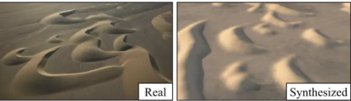
Real Synthesized
Figure 16: Comparison of real (left) and synthesized (right) barchan dunes; no user interaction was needed to create this scene.
7.2. Validation
Figure 16 shows a comparison between real and synthesized barchan dunes. While our method lacks sharp ridges due to the insufficient grid resolution, we succeed in capturing the overall shape and placement of the dunes. Moreover, we are able to recre-ate a large number of desert features: transverse, barchan, linear, climbing and star dunes, as well as yardangs produced by abra-sion as demonstrated in Figures10,12, 14and17. This qualita-tively validates the overall coherency of our simulation. We man-aged to reproduce complex phenomena and results are consistent with observations and numerical simulations done in geomorphol-ogy [Wer95,Baa02,MCGBW00].
A more complete quantitative validation of approach is difficult: currently available elevation data is not accurate enough to capture detailed desert landforms. A comparison with dense and accurate
A. Paris et al. / Desertscape Simulation
Barchans Abrasion Transverse
Nabkha Mega Barchan Star
Figure 17: Starting with a bare bedrock covered by a small amount of sand, barchans emerged because of the low sand supply and the uniform wind conditions. The user then triggered abrasion which shaped yardangs parallel to the wind direction. Then, sand was uniformly added over the entire scene, which transformed barchans into transverse dunes. Vegetation was later added on the right side of the scene, which yielded nabkha. Mega-barchans started to appear after many iterations, as observed in nature. Finally, the user removed some sand to get a more uniform sand layer, destroyed vegetation and created large dome dunes by changing wind rose parameters.
real elevations would be an interesting research direction worth in-vestigating.
7.3. Comparison with other techniques
To our knowledge, our model is the first to capture such a wide vari-ety of desert landforms. Previously published methods either focus on generic hydraulic or thermal erosion which primarily generate Alpine mountain ranges.
Previous works directly dealing with the saltation pro-cess [ON00,BR04] target the specific application of sand ripples at a much lower scale than our method. In contrast, our approach is more general and thus achieves a wider range of desert features. Other specific works only apply to a limited range of ventifacts such as Goblins [BFO∗07,JFBB10] which also belong to the small scale class of phenomena. In a sense, these works can be seen as com-plementary to ours, as they could be used to amplify desertscapes with details.
Closer in spirit to our approach is the work of [CGG∗17] that combines (hydraulic, thermal and lightning) terrain erosion and ecosystem simulation in a unified framework. Our method extends this work and could be seamlessly integrated to it as it also relies on the definition of stochastic events.
7.4. Limitations
Our model produces dune topography and landforms similar to the ones observed in geomorphology. Our model still has some limita-tions. First, the simulation grid is currently limited to 1024 × 1024 resolution in order to maintain acceptable computation time and allow for simultaneous interactive editing and control. The simula-tion could be accelerated by carefully implementing the algorithm
on graphics hardware, which is beyond the scope of this paper. An-other limitation commonly accepted for all grid-based terrain ero-sion simulations is the lack of preciero-sion. Eroded bedrock and sand dunes may have sharp features, such as crests or ridge lines, which cannot be directly captured because of the resolution simulation (recall that grid cells have 1 − 10 m size). One solution would be to use amplification combined with procedural primitives in the spirit of [GGP∗15] to restore the sharpness of the terrain.
A wider range of effects observed in geomorphology could be incorporated in our model. For instance, echo dunes [Tso83] which form on the windward side of cliffs or escarpments, are separated from the scarp by a sand-free region and are the product of the complex movement of wind, forming a fixed eddy between the es-carpment and the dune. Such dunes could be obtained by improv-ing the procedural wind warpimprov-ing and shadowimprov-ing model with proce-durally generated edits. Our small scale user-controlled wind field currently partially leverages this limitation.
8. Conclusion
We introduced a complete aeolian erosion and transport simula-tion to the field of computer graphics. Derived from the high al-titude wind is the fast approximation and computation of the sur-face wind, taking into account relief shadowing at different scales, which is central to the simulation of sand transport. In turn, salta-tion, reptation and avalanching processes are simulated in a con-sistent framework and combined with bedrock erosion to simulate abrasion as well as vegetation shielding to create nabkha.
Our model is versatile and capable of generating all the differ-ent dune types as well as abrasion effects on the bedrock. However, obtaining a specific design scene from a simulation is a challeng-ing task, requirchalleng-ing many trial and errors, especially for complex
dune shapes. A direct extension to this work would be to incorpo-rate a variety of complex wind scenarios to guide the simulation. An even more noteworthy albeit challenging avenue of future re-search would be to learn the correlations between the wind and the generated features in an inverse procedural way. Learning which parameters of the simulation lead to some specific dunes distribu-tions and shapes could lead to new insights on how certain types of dunes form and evolve.
Acknowledgments
This work was part of the project PAPAYA funded by the Fonds National pour la Société Numériqueand the project HDW ANR-16-CE33-0001, supported by Agence Nationale de la Recherche. References
[Baa02] BAAS A. C.: Chaos, fractals and self-organization in coastal geomorphology: simulating dune landscapes in vegetated environments. Geomorphology(2002), 309 – 328.2,3,4,7
[BFO∗07] BEARDALLM., FARLEYM., OUDERKIRKD., REIMSCHUS-SELC., SMITHJ., JONESM., EGBERTP.: Goblins by spheroidal weath-ering. In Proceedings of Third Eurographics Conference on Natural Phe-nomena(2007), pp. 7–14.2,8
[BHN07] BRIDSONR., HOURIHAMJ., NORDENSTAMM.: Curl-noise for procedural fluid flow. ACM Transactions on Graphics 26, 3 (07 2007), 46:1–46:3.4
[BR04] BENEŠB., ROAT.: Simulating desert scenery. In WSCG Pro-ceedings of the 12-th International Conference in Central Europe on Computer Graphics, Visualization and Computer Vision(2004), pp. 12– 18.2,8
[BYJM05] BELLN., YUY., J. MUCHAP.: Particle-based simulation of granular material. In Proceedings of the Symposium on Computer Animation(2005), pp. 77–86.2
[CBC∗16] CORDONNIERG., BRAUNJ., CANIM.-P., BENESB., ÉRIC GALIN, PEYTAVIEA., ÉRICGUÉRIN: Large scale terrain generation from tectonic uplift and fluvial erosion. Computer Graphics Forum 35, 2 (2016), 165–175.2
[CCB∗18] CORDONNIER G., CANI M.-P., BENES B., BRAUN J., GALINE.: Sculpting mountains: Interactive terrain modeling based on subsurface geology. IEEE Transactions on Visualization and Computer Graphics 24, 5 (2018), 1756–1769.2
[CGG∗17] CORDONNIERG., GALINE., GAINJ., BENESB., GUÉRIN E., PEYTAVIEA., CANIM.-P.: Authoring Landscapes by Combin-ing Ecosystem and Terrain Erosion Simulation. ACM Transactions on Graphics 36, 4 (2017), 134.2,5,8
[CWG06] COOKER., WARRENA., GOUDIEA.: Desert Geomorphol-ogy. 2006.6
[DBD16] DAVIETG., BERTAILS-DESCOUBESF.: A Semi-Implicit Ma-terial Point Method for the Continuum Simulation of Granular MaMa-terials. ACM Transactions on Graphics 35, 4 (2016), 102:1–102:13.2
[GGP∗15] GÉNEVAUX J.-D., GALINE., PEYTAVIE A., GUÉRIN E., BRIQUETC., GROSBELLETF., BENESB.: Terrain modelling from fea-ture primitives. Computer Graphics Forum 34, 6 (2015), 198–210. 2,
8
[GGP∗19] GALINE., GUÉRINE., PEYTAVIEA., CORDONNIER G., CANIM.-P., BENESB., GAINJ.: A review of digital terrain modeling. Computer Graphics Forum (Proceedings of Eurographics 2019 STAR) 38, 2 (2019), 553–577.2
[GWA∗08] GROH C., WIERSCHEM A., AKSEL N., REHBERG I., A KRUELLEC.: Barchan dunes in two dimensions: Experimental tests for minimal models. Physical review. E, Statistical, nonlinear, and soft matter physics 78(2008).6
[Hug03] HUGGETTR.: Fundamentals of Geomorphology. Fundamentals of Geomorphology. Routledge, 2003.2
[JFBB10] JONESM., FARLAYM., BUTLERM., BEARDALLM.: Di-rectable weathering of concave rock using curvature estimation. IEEE Transactions on Visualization and Computer Graphic 16, 1 (2010), 81– 97.2,8
[Lan95] LANCASTERN.: The Geomorphology of Desert Dunes. Physical Environment Series. Rootledge, 1995.2
[LBS13] LANCASTERN., BAASA., SHERMAND.: 11.1 Aeolian Geo-morphology: Introduction, vol. 11. Elsevier Academic Press Inc, 2013, pp. 1–6.2,3
[MCGBW00] MOMIJI H., CARRETERO-GONZALEZ R., BISHOP S., WARRENA.: Simulation of the effect of wind speedup in the forma-tion of transverse dune fields. Earth Surface Processes and Landforms 25(2000).2,7
[MKM89] MUSGRAVEF. K., KOLBC. E., MACER. S.: The synthe-sis and rendering of eroded fractal terrains. Computer Graphics 23, 3 (1989), 41–50.2
[NZRC09] NARTEAUC., ZHANGD., ROZIERO., CLAUDINP.: Setting the length and time scales of a cellular automaton dune model from the analysis of superimposed bed forms. Journal of Geophysical Research: Earth Surface 114, F3 (2009).2
[ON00] ONOUEK., NISHITAT.: A method for modeling and rendering dunes with wind-ripples. In Proceedings of the Pacific Conference on Computer Graphics and Applications(2000), IEEE, pp. 427–428.2,8
[PT09] PYEK., TSOARH.: Aeolian Sand and Sand Dunes. Unwin Hy-man, London, 2009.2
[RPP93] ROUDIERP., PEROCHEB., PERRINM.: Landscapes synthesis achieved through erosion and deposition process simulation. Computer Graphics Forum 12, 3 (1993), 375–383.2
[ŠBBK08] ŠTAVAˇ O., BENEŠB., BRISBINM., KRIVÁNEKˇ J.: Inter-active terrain modeling using hydraulic erosion. In Proceedings of the Symposium on Computer Animation(2008), pp. 201–210.2
[Tso83] TSOARH.: Wind tunnel modeling of echo and climbing dunes. In Eolian Sediments and Processes, vol. 38. Elsevier, 1983, pp. 247–259.
8
[Wer95] WERNERB. T.: Eolian dunes: Computer simulations and attrac-tor interpretation. Geology (1995).2,3,5,7
[WG84] WARD A. W., GREELEYR.: Evolution of the Yardangs at Rogers lake, California. GSA Bulletin 95 (1984), 829 – 837.2
[YJL∗16] YANX., JIANGY.-T., LIC.-F., MARTINR. R., HUS.-M.: Multiphase SPH simulation for interactive fluids and solids. ACM Trans-actions on Graphics 35, 4 (2016), 79:1–79:11.2
[ZB05] ZHUY., BRIDSONR.: Animating sand as a fluid. ACM Trans-actions on Graphics 24, 3 (2005), 965–972.2
[ZNRCdP12] ZHANG D., NARTEAUC., ROZIERO., COURRECH DU PONTS.: Morphology and dynamics of star dunes from numerical mod-elling. Nature Geoscience 5 (2012), 463–467.2