HAL Id: hal-02019484
https://hal-univ-rennes1.archives-ouvertes.fr/hal-02019484
Submitted on 5 Mar 2019HAL is a multi-disciplinary open access archive for the deposit and dissemination of sci-entific research documents, whether they are pub-lished or not. The documents may come from teaching and research institutions in France or abroad, or from public or private research centers.
L’archive ouverte pluridisciplinaire HAL, est destinée au dépôt et à la diffusion de documents scientifiques de niveau recherche, publiés ou non, émanant des établissements d’enseignement et de recherche français ou étrangers, des laboratoires publics ou privés.
How microwaves can help to study membrane ageing
M Rabiller-Baudry, L Paquin, C Lepéroux, H Diallo, H Al Jawad, C Sepré
To cite this version:
M Rabiller-Baudry, L Paquin, C Lepéroux, H Diallo, H Al Jawad, et al.. How microwaves can help to study membrane ageing. Environmental Technology, Taylor & Francis: STM, Behavioural Science and Public Health Titles, 2020, 40 (1), pp.1-46. �10.1080/09593330.2018.1564072�. �hal-02019484�
1 Publisher: Taylor & Francis & Informa UK Limited, trading as Taylor & Francis Group Journal: Environmental Technology
DOI: 10.1080/09593330.2018.1564072
Revised paper - submitted to Environmental Technology, December 18, 2018
How microwaves can help to study membrane ageing
Rabiller-Baudry M.a*, PaquinL.a, Lepéroux C. a, Diallo H. a, Al Jawad H.a,b, Sepré C.a
a Univ Rennes, CNRS, ISCR (Institut des Sciences Chimiques de Rennes) - UMR 6226,
F-35000 Rennes, France.
b Université Libanaise, Laboratoire de Biotechnologie Appliquée: Biomolécules, Biothérapies
et Bioprocédés du Centre AZM pour la Recherche en Biotechnologie et ses Applications, Beyrouth, Lebanon
2
How microwaves can help to study membrane ageing
AbstractThis paper studies original protocols of rapid PES/PVP membrane NaOCl degradation allowing at reaching ageing states that are representative of industrial ageing. The long term objective is to propose basis for further fundamental studies aiming at the improvement of the impact of membrane ageing on behavior in UF (fouling and cleaning mastering). The key of several protocols is the use of ageing acceleration thanks to microwave irradiation, either continuous or pulsed ones, that can be further associated (or not) with short ageing time in UF conditions. To evaluate the representativeness of obtained aged membranes, comparisons are achieved between pristine, voluntary laboratory aged membranes and an industrial membrane at the end of its service-life. Several physico-chemical analyses were used (ATR-FTIR, SEM-EDX, contact angle, SEC-HPLC). Evaluation of UF performances were made in UF of a model protein (Lysozyme, 14,300 g.mol-1). Finally, the proof of concept is done that
conditions using MW exist to reach ageing state representative of industrial ageing.
Keywords: PES/PVP membrane; ageing; microwaves irradiation; ATR-FTIR; contact-angles; SEM-EDX; SEC-HPLC; UF
Word count: 7976 (main part only- abstract, acknowledgement, references, nomenclature section, tables and figures are excluded)
1. Introduction
At industrial scale, increasing difficulties in fouling and cleaning are often encountered in the second part of the membrane life. Disruptions occur at unpredictable times and membranes have sometimes to be changed in emergency. To avoid such stress, several factories use to renew membranes at a preselected service life duration before disruption. None of these two strategies is really a sustainable one, but can be justified by the lack of
3 fundamental understanding of membrane ageing at industrial scale. To go ahead we have started ten years ago, a systematic study of the impact of the membrane ageing on disruptions, knowing that itis probably the consequence of the combination of both chemical and mechanical impacts, as explained by Pellegrin et al., [1, 2] .
In dairy, polyethersulfone/polyvinylpyrrolidone (PES/PVP) membranes are commonly used in ultrafiltration (UF) of skim milk for the standardization of the protein content before the cheese making process or for the filtration of acid and rennet whey. For these applications, membranes are twice daily cleaned with cascades of formulated detergents. Classically an alkaline cleaning step and an acid one, often with nitric acid, are achieved. After the cleaning in place (CIP) by these two solutions, a final disinfection step and a water rinsing are added, before the production start again. The main difference between the3different cases of the dairy industry is the nature of the alkaline and acid cleaning solutions. However, their order and real effect in the cascade are also questioned. Several studies have reported that the chemical ageing of PES/PVP UF membranes is not related to the alkaline formulated detergent the pH of which is in the range 11.5-12.0. Similarly, the nitric acid step, for which the pH is close to 1.6 is not responsible of the membrane chemical ageing. For instance, we have previously shown that the nitric acid step is harmlessness towards these membranes even
after soaking in more concentrated HNO3 solution and up to 1 mol.L-1 owing a null pH [3-6].
Moreover a PES/PVP nanofiltration membrane has been reported to be stable over a year after
immersion in 5.9 mol.L-1 phosphoric acid that is a very concentrated solution with a
„negative‟ pH [7].
Nowadays, it is well-known that the disinfection step is the main responsible of the PES/PVP membrane ageing, especially when it is achieved in oxidant conditions obtained by chlorine based disinfectants (see for instance [8-12] . Classically in dairy NaOCl (bleach) solutions are set at 150-200 ppm in total free chlorine (TFC) and pH close to 11.0-11.5 and used at 50°C. However, NaOCl induces more or less degradation of the two polymers constituting the membrane (Figure 1).
Insert Figure 1 about here
PVP, the minor but „hydrophilic‟ constituent of the membrane, has been shown to lead to intermediate degradation products after contact with NaOCl at pH= 7.0 - 8.0. After a long time contact, that is not clearly evaluated, PVP totally disappears. It can be underlined that such pH range is the more favorable one to induce degradation according to a radical mechanism. . These intermediates have not been evidenced after contact with NaOCl at pH= 11.5 [11]. Nevertheless, the full disappearance of PVP after long term NaOCl treatments at pH= 11.0-11.5 achieved at industrial scale has been confirmed by autopsy of membranes at the end of their service life [3-5] . Regardless of the NaOCl pH the removal of PVP might induce an increase in the membrane hydrophobicity.
PES is simultaneously the main polymer and the more hydrophobic one of the membrane. Different evolutions due to oxidizing treatments are reported in literature. It goes from simple hydroxylation of the phenyl groups, a slight modification that is compatible with an increase in hydrophilicity of the membrane, to the cleavage of a C-S covalent bond of the PES
backbone leading to formation of sulfonate (~SO3-) fixed groups attached to the aged
membrane. This last modification is in good agreement with an increase in the overall membrane hydrophilicity with respect to the presence of charges.
The conditions of the occurrence of the two modes of PES degradation are still controversial, probably with respect to the NaOCl ageing duration used in the studies that are always achieved in different conditions, for instance with respect to the concentration. On one hand, Yadav and Morison [10] have proposed the cleavage of C-S covalent bond of the backbone at
4 high alkaline pH. On the other hand, Hanafi et al. [13-14] have found, from streaming potential (SP) measurements, that the backbone cleavage occurs at pH= 60.-8.0 but not at pH= 11.5. Moreover their SP measurements for PES/PVP membranes aged in NaOCl agreed with the hydroxylation of the phenyl group at pH 6.0-8.0 and pH= 11.5. The same authors have also proved that the two evolutions of PES can co-exist at pH= 6.0.
It can be noticed that direct ATR-FTIR analysis on membranes (a technique that will be used in the present study) is not able to distinguish between the two mechanisms as the two PES possible evolutions lead to a new band located exactly at the same wavenumber close to 1030 cm-1.
A difficulty to study the impact of membrane ageing at lab. scale is the availability of aged membranes at different steps of their service life without any other variations. To collect industrial membranes is generally difficult for economic reasons. Moreover it is not sufficient because such membranes are generally fouled by proteins (even when having carefully be cleaned) and it becomes quite complicated to discriminate if the changes in the membrane performances are due to either residual fouling or membrane ageing or a combination of the two. That is why, in the present study, we have chosen to voluntary aged membranes by immersion in NaOCl solutions using different protocols aiming at finding one that can be rapid and able to lead to ageing representative of ageing state reached at industrial scale. Among several assays reported in this paper, the most original approach is based on the use of ageing acceleration thanks to micro-waves (MW) irradiation. MW activation of reactions is now commonly used for synthesis in organic chemistry [15]. For a better understanding of the reasons having conduced us to select MW irradiation, the next paragraph gives some generalities on MW activation.
2. Micro-wave activation of reactions
2.1. Microwaves in chemistry
Microwave (MW) irradiation is nowadays a well-established technology in organic chemistry laboratories [15, 16]. Microwave assisted chemistry is based on the use of intensive directed irradiation and its purposeful application can have several advantages such as short heating times, wide usable temperature and pressure range, accumulation of energy added to the system, inversion of heating flux in the reactor, higher energy efficiency, sophisticated measurement and safety technology, modular systems that allow changes from the milligram up to the kilogram scale [16].
Essential to chemical synthesis are reaction equilibrium conditions and how rapidly they can be reached. MW reaction rates are several times faster than conventional heating, because the energy efficiency is higher due to the fact that the solvent is rapidly/directly heated, thus eliminating the energy required to raise the temperature of the containing vessels [17].
MW electromagnetic energy has gained significant attention in domestic, medical, pharmaceutical and industrial applications such as for domestic microwave oven applications, for pasteurization, sterilization [18] or at lab scale to prepare product of high quality [19]. Similarities and differences between the conventional and MW heating mechanisms in terms of yield and purity of products have been reviewed by Nuchter et al. [20]. However, significant technological problems arise in attempting to scale up to production scales, particularly due to the restricted penetration depth of microwave irradiation in absorbing materials. Nevertheless, industrial oven already exists and are used for various applications (Figure 2). The possible scale-up is an important aspect for us because it means that our methodological approach could also be developed on membrane of industrial size and not only on small flat membrane as it will be shown in this paper.
5
Insert Figure 2 about here 2.2. micro-wave effects
Microwaves are a part of the electromagnetic spectrum occurring in the frequency range of 300 MHz to 300 000 MHz (Figure 3).
Generally domestic as well as laboratory ovens deliver MW at 2,450 MHz with a wavelength
of 12.2 cm corresponding to a quantum of energy of about 1 J.mol-1 (0.23 cal.mol-1).
For a given power P= 680 W, the delivered energy is 680 J.s-1. Considering a classical
chemical reaction requiring an energy of activation of 209 kJ.mol-1 (50 kcal.mol-1), it takes
about 5 min.mol-1 (time = 209,000/680= 307 s) to deliver such energy that is a high value
with respect to the small quantities generally placed in the MW oven cavity.
Insert Figure 3 about here
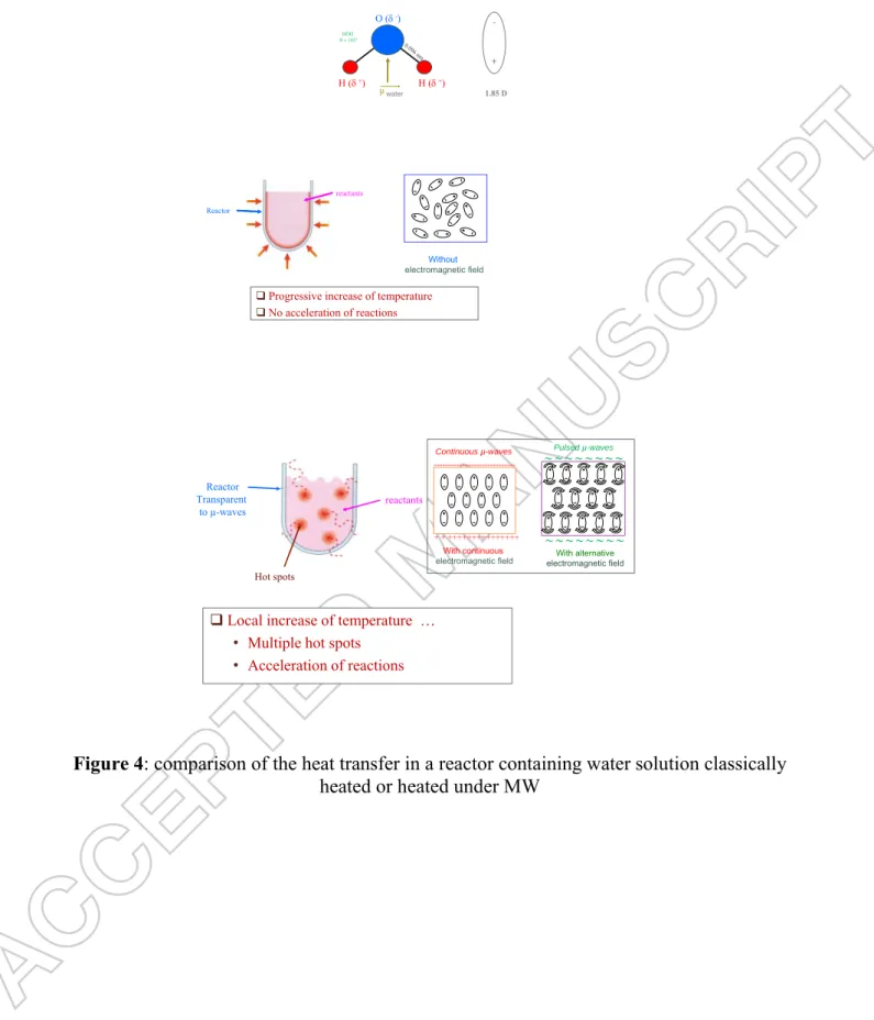
MW effects can be classified into thermal and non-thermal ones. The thermal effects result from microwave heating and are due to rapid heating, volumetric heating, superheating, hotspots and selective heating while the non-thermal effects are associated with surface polarization [21].
The principal heating mechanisms of MW are due to dipolar polarisation, conduction mechanism and interfacial polarisation. The dipolar polarisation is responsible for most of the heating observed in solvent systems while the conduction mechanism occurs when an electrical conductor is irradiated with MW leading to the movement of charge carriers under the influence of an electric field resulting in polarisation. The combination of both processes produces interfacial polarisation in systems comprising both conducting and non-conducting materials [21].
2.3. Media on which MWs are applied
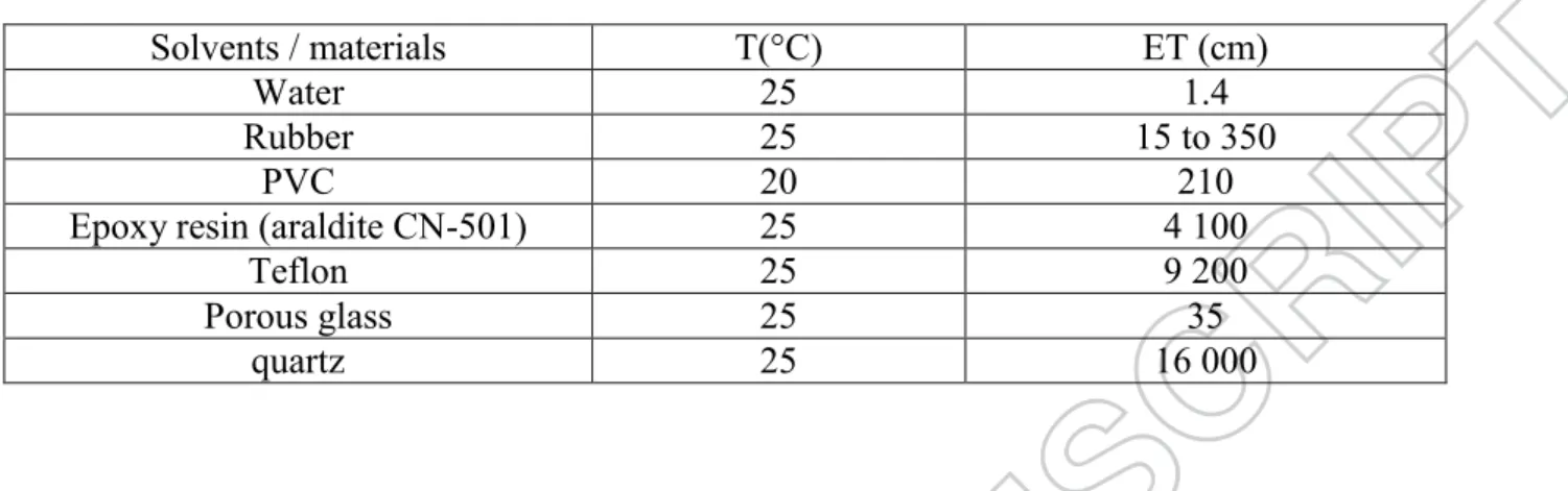
The success of the MW irradiation in chemical reactions largely depends on the electromagnetic field distribution in the volume of the solvent/reactants mixture inserted in the oven cavity. The MW penetration depth (ET) depends on materials and particularly on their dielectric constant (equation 1).
ET = ( / 2 ). ( ‟r1/2 /"r) (1)
With :
ET : the penetration depth of MW (cm)
the wavelength of the MW (cm)
‟r : the dielectric constant of the medium (measure of the ability of the molecules to become
polarised by an external electric field)
"r : the dielectric loss of the molecule (measure of the efficiency with which electromagnetic energy can be converted into heat, it usually goes through a maximum as the dielectric constant is decreased)
= 12.2 cm at 2,450 MHz
Microwave absorption via dielectric heating depends on the imaginary part of the material permittivity. The higher is the imaginary part of the permittivity, the higher is the absorbance. The ratio of the dielectric loss to the dielectric constant is defined as the dielectric loss
6 tangent, tan δ, which is an important number for characterising microwave heating [22]. Several authors considered that tan δ is representative of the absorption because it reveals the compromise between the two parameters mentioned just above.
Table 1 shows some typical values of penetration depths. Whereas metals and graphite are fully reflective, water that owns a high dielectric constant is a strong microwaves absorbent. This property can be used to accelerate chemical reactions in water solution but it induces a difficult temperature control during MW irradiation and a sudden increase in temperature can easily be observed that might favor the formation of undesirable side-products.
Organic polymers such as PVC appear as intermediate absorbents of MW and probably it is also the case for PES and PVP, but unfortunately no information has been found dealing with these two polymers constituting the membrane studied in the present paper.
On the contrary quartz is quasi fully transparent and appears as a nice material to use for reactor fabrication when reaction is achieved in a liquid medium. Porous glass is less interesting with respect to the energy efficiency. Nevertheless, taking into account the cost and practical aspects, as well the possible scale-up, glass reactors have been used in the following.
Insert Table 1 about here
The MW penetration depth (ET) depends also on the temperature and for instance in water ET increase from 1.4 cm to 5.7 cm at 25°C and 95°C, respectively.
Finally, it must also be said that the boiling points of polar solvents are higher under MW (Nucleation Limited Boiling Temperature, NLBT) than without MW as shown for a selection of solvents in Table 2. This possible local increase of temperature allows acceleration of reactions with MW irradiation compared to a reactor classically heated (Figure 4).
Insert Table 2 about here Insert Figure 4 about here
The power transferred to a reaction mixture by MW is of course of great importance and is given by the following equation:
Pd = ( + 2 π ν ε”r) │E│2 (2)
With
Pd : the power transferred per unit volume of material
: the medium conductivity
ε'r : the dielectric constant of the medium E : the local electric field intensity of MW
ν : the MW frequency (often set at 2450 MHz)
To reach and maintain a temperature corresponding to the actual industrial one applied during membrane disinfection by bleach (50°C) we have experimentally checked that the required power was close to 60 W. Although, increasing the power level was a good way to increase membrane degradation but much more attention had to be paid to reach an acceptable temperature.
7 Two different types of ovens exist: the most sophisticated are single-mode ovens running in continuous mode whereas the simpler ovens are multi-mode ones acting in a discontinuous mode. These two oven types allow more or less subtle assays and will be quickly described in the following because both of them have been used in the present study.
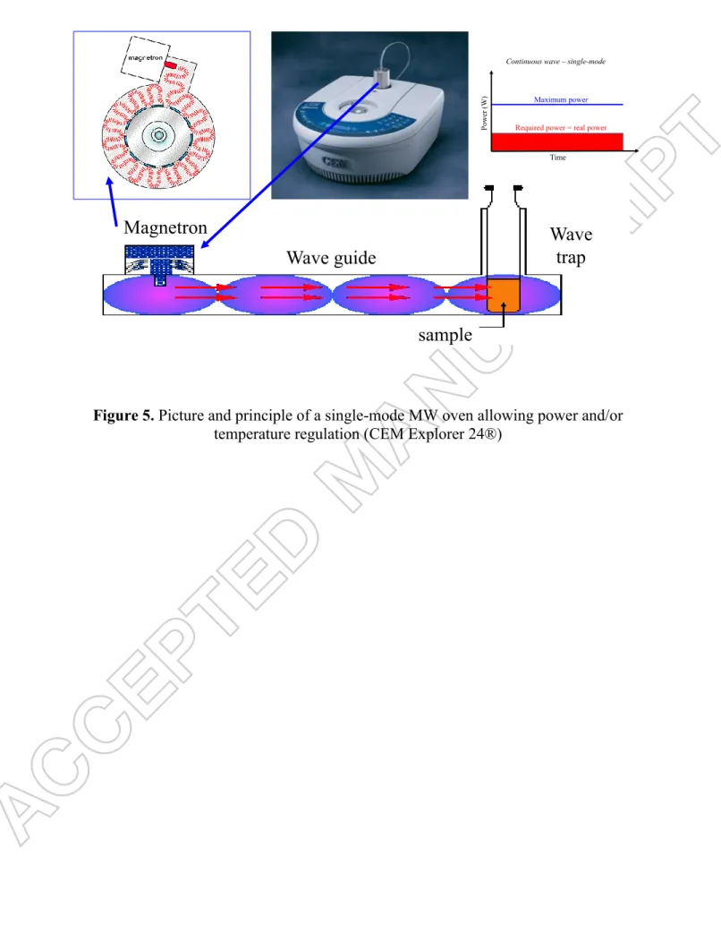
2.3.1. Continuous MW / single-mode oven. Figure 5 shows a single mode oven and the
principle of wave-guidance up to the sample located in a small cavity. The use of such oven allows the definition of precise positions within the oven, exactly where the electric field intensity is maximum. Remember that the positions of the maximum electric field intensities change from the maximum to zero in a distance of one-quarter of the operating wavelength (E typically follows a half sinus-wave pattern, Figure 3, called the “standing wave effect”). The effect linked to the well-chosen position of the sample in the electric field is observed immediately after applying the MW power and therefore it only needs few minutes for the solution to reach a uniform heating state (Figure 5). Accordingly, both temperature and power fine controls are possible (Figure 6).
The only disadvantage of such oven for the present study is that only small membrane coupons can be studied because the solution must be contained in 10 ml vessels up to 100 ml round-bottomed borosilicate glass flasks (chosen here), preventing from further filtration tests, but the magnetic stirring is possible to enhance the solution homogeneity.
Insert Figure 5 about here Insert Figure 6 about here
2.3.2. Pulsed (discontinuous) MW and multi-mode oven. Figure 7 shows multi-mode ovens
delivering pulsed MW. Contrary to the previous one, the power is applied discontinuously, meaning that its regulation is far from be nicely controlled. Another consequence is the absence of mastering of the temperature. To avoid too high increase in temperature, the experimenter has to manually choose to apply power for a given time that has to be experimentally determined according to the objectives dealing with temperature limitation. For instance, Figure 8 depicts that the size and form of the reactor as well as the number of reactors simultaneously presents in the oven can significantly modify the water evaporation rate and consequently the concentration of reactants and thus the results with a given power and oven. The size to volume ratio of membrane to solution as well as the overall matter present in the oven must be controlled for study optimisation.
Insert Figure 7 about here Insert Figure 8 about here
2.3.3. Optimisation depend on the MW oven. More or less, all ovens, either laboratory or
domestic ones, have the same magnetron, but even at constant frequency (generally 2,450 MHz) and same applied power, optimised reaction conditions are oven-dependent. This is due to the difference in the statistical distribution of the waves inside the oven, that depends on several parameters such as: the different systems to guide (waveguide) and disperse the waves (wave brewer) toward the sample inside the oven, the power supply unit, the cavity size of the oven and of course the overall volume and chemical nature of the samples in the cavity. That is why in the present study we have systematically performed experiments with constant membrane to solution ratio and constant number of glass reactors (always the same series) in
8 the multi-mode oven (see experimental part). The question is less sensitive with the single-mode oven because only one sample can enter the very small cavity but similar precautions have been taken.
2.5 conclusion on MW
To sum up, chemical reactions under MW irradiation are affected by overheating, hot spot formation, polarization, dielectric properties, solvent sensitivity to microwaves, spin alignment and nuclear spin rotations. Considering the large use of MW for synthesis purpose and knowing that degradation involved similar chemical mechanisms as synthesis, we have decided ten years ago to systematically study „How micro-waves can help to study membrane ageing and consequences on fouling and cleaning‟. This paper is the first one giving the overall trends that underpin and validate the approach.
3. Materials and Methods
3.1. Water and solutions
Water used for membrane rinsing and preparation of all solutions was demineralised and 1 µm filtered. In standard conditions (except other comments) sodium hypochlorite (NaOCl) concentration, was set at 400 ppm TFC and used either at pH = 11.5 ± 0.1 or pH= 8.0 ± 0.1 by addition of NaOH or HCl of analytical grade (Acros), respectively. It was obtained by appropriate water dilution of concentrated commercial bleach (MIC, bleach at
96,000 ppm TFC). A formulated alkaline detergent (Ultrasil 10, powder, pH 12.0 at 4 g.L-1)
provided by Ecolab (Issy Les Moulineaux, France) was used for membrane cleaning. This detergent is known to be efficient for the protein removal from pristine PES/PVP membrane [23].
Lysozyme from hen egg white (MW= 14,300 g.mol-1, isoelectric point pI= 10.7, Stokes radius
Rs= 1.8 nm) in hydrochloride form was provided by Ovonor (Tregueux, France). This protein
has been chosen because its size is close to that of -lactalbumin, the smallest soluble protein
of milk, but lysozme was less expensive. Solutions set at 1 g.L-1 were filtered at natural pH
(pH = 4.5). In such physico-chemical environnement, Lysozyme was highly positively charged. Occurrence of charge on the filtered protein induce occurrence of similar charges on the fouled membrane. Accordingly, repulsive electrostatic interactions were efficient between lysozyme free in solution and the fouled membrane. The consequnce is the enhancement of the protein rejection by the membrane when compare to pure size exclusion [24]. Addition of salt at sufficient concentration allowed to screen these electrostatic interactions. This allowed to reach transfer mechanism mainly based on steric exclusion and not on the combination of steric and electrostatic repulsions. This filtration conditions were better to appreciate the
impact of membrane ageing on protein rejection. Consequently, NaCl solution at 500 mmol.L
-1 were prepared from powder of analytical grade (Acros) and sometimes added to ultrafiltered
lysozyme solutions..
3.2. Membranes and UF conditions
3.2.1. Membranes. The UF membrane (HFK 131, 5-10 kg.mol-1) was provided by Koch (USA). This membrane is worldwide commonly used at industrial scale for UF in dairy industry. HFK-131 is mainly made of PES but contains also some PVP [25]. One spiral
membrane (6.7 m2, 4333 K131 VYV module) was used in which flat coupons of 127 cm2
9
3.2.2. Filtration with flat membranes. Prior any other use, the preservative (glycerol) was
removed by soaking the flat membrane in demineralised water (removal was checked by ATR-FTIR analysis). Then the membrane was inserted in a plate and frame cell (Rayflow X100, Orelis, France). Each flat membrane was compacted by filtering water at 3 bar, 25°C,
during 4 h in cross-flow mode (velocity close to 2 m.s-1) until a plateau value of permeance
(Lp0 = J0,water /TMP) was reached. Several virgin membranes were used in lysozyme UF. The
following UF standard conditions were: 50°C, 2 m.s-1, transmembrane pressure TMP= 2 bar
and VRR=1 (full recycling of permeate and retentate in the feed tank). Others membranes were voluntary aged in NaOCl according to various protocols tested (see below). After the ageing treatment, hey were re-compacted at 3 bar in water and finally used in lysozyme UF in standard conditions. The careful rinsing as well as the re-compaction together with the temperature control during water flux measurement were required because this membrane is both pH and temperature responsive. Precision on fluxes was better than 5%. Regardless of the membrane, either virgin or NaOCl aged, after lysozyme UF, each membrane was carefully rinsed by water. Then the membrane was demounted for analysis.
3.3. Protocols for flat membrane ageing
Regardless of the protocol, the treatment duration varied. It is commonly expressed as a cumulative dose of NaOCl received by the membrane and generally given in ppm.d total free chlorine (TFC). According to the provider the HFK-131 membrane was guaranteed up to a cumulative NaOCl dose equal to 5,000 ppm.d TFC. For a „D‟ ppm TFC NaOCl solution, the received dose was expressed according to:
NaOCl dose (ppm.d) = D (ppm) x number of days (3)
3.3.1. Ageing by soaking in NaOCl. Small membrane coupons of about 10 cm2 and 127 cm2 filtering area flat membranes were soaked in NaOCl solutions at given concentration in the 0 to 96,000 ppm TFC range up to 200 days. Moreover the pH was fixed either at pH= 8.0 (ideal for PES/PVP degradation, and corresponding to a pH commonly used in water applications at room temperature) or pH= 11.5 (less favourable to prone PES/PVP membrane degradation but corresponding to pH commonly used in dairy applications at 50°C). The temperature was maintained at 50°C all day long and decreased slowly during the night down to room temperature. Solutions were replaced every week. Regardless of the other conditions, the
NaOCl solution volume to membrane area ratio was always 14.6 L.m-2. This ratio was more
or less arbitrary chosen but it was the same that was used in UF with respect to the pilot dead volume.
3.3.2. Ageing in UF conditions at 2 bar. Flat membranes of 127 cm2 filtering area were
continuously immersed in 400 ppm TFC NaOCl solution at pH 8.0 (14.6 L.m-2) on a UF pilot
filtering all day long at 50°C. However the filtration was stopped during the night but the membrane remained immersed in the NaOCl solution. The temperature was able to slowly decrease during the night down to room temperature. Finally it was estimated that UF ageing was only one third of the time performed in the standard hydrodynamic conditions described above.
3.3.3. Accelerated ageing by immersion under continuous microwaves (60-70 W). Small
membrane coupons (14.6 L.m-2) were immersed in NaOCl solution set at 400 ppm TFC at
either pH= 8.0 or pH= 11.5. Simultaneouslys they were submitted to continuous micro-waves irradiations at 60 W that were applied during few hours in a CEM Explorer® 24 single-mode
10 oven (Labmate, 2,450 MHz, Figure 5). The microwave irradiation parameters (power and temperature) were monitored by the ChemDriver software.
The limitation of the power allowed to control the temperature that was kept constant at 50 ± 1 °C (Figure 6).. The membrane coupons were exposed to MW irradiation for either 120 min (33.3 ppm.d TFC dose) or 240 min (66.7 ppm.d TFC dose). However, this oven had a too
small cavity to insert 127 cm2 membrane preventing thus from possibility of further UF tests.
3.3.4. Accelerated ageing by immersion under pulsed microwaves (680 W). Small membrane
coupons of 10 cm2 area (always the same numbers simultaneously in the oven) or 127 cm2
filtering area flat membrane (only one in the oven) (14.6 L.m-2) were immersed in NaOCl solution set at 400 ppm TFC either at pH= 8.0 or pH= 11.5. They were submitted to pulsed microwaves at 680 W in a discontinuous mode that was applied few minutes in a multi-mode domestic oven (Moulinex, 31 L, 2,450 MHz, Figure 9). In order to limit the temperature increase, and to try to be as close as possible to conditions of the single-mode oven described above, each 3 min the warm NaOCl solution was changed for a similar volume of a fresh one initially at room temperature. The membranes were exposed to micro-waves irradiation for a maximum duration of 45 min (12.5 ppm.d TFC dose).
Insert Figure 9 about here
3.3.5. Combination of ageing in UF conditions then pulsed micro-waves (170 W). Several flat
membranes of 127 cm2 filtering area had continuously filtered a 400 ppm TFC solution at pH= 8.0 until a 500 ppm.d TFC dose exposition (14.6 L.m-2, in standard UF conditions, 50°C). After this first ageing step, the membranes were demounted and immersed in 400 ppm
TFC solution at pH 8.0 (14.6 L.m-2) under pulsed microwaves (170 W, Moulinex) for a given
duration that was maximum 12 h (corresponding to a 700 ppm.d TFC maximum cumulative dose). Finally the membranes were carefully rinsed by water, compacted once again and finally used in UF.
3.4. Physico-chemical characterisation of membrane by ATR-FTIR
Membrane degradation by NaOCl as well as protein amount on membrane was followed by ATR-FTIR. Prior to measurements membranes were carrefully dried in a dessiccator under dynamic vacuum during several days in order to get rid of water. The
dryingefficiency was checked on all spectra via the absence of the OH band in the 3000 cm-1
region allowing to estimate that the OH band harmonic, much lower than the previous one
and located close to 1660 cm-1 was null. Spectra were aquired with a spectrum 1000
spectrometer (Perkin Elmer, spectrum for windows software) equipped with an ATR
accessory (ZnSe Crystal, 12 reflexion, incidence angle of 45°, 20 scans, resolution: 2 cm-1).
Membrane samples were carefully pressed on the crystal (maximum pressure using a flat tip) for a nice signal to noise ratio. Figure 10 shows typical spectra of new membranes. All bands
can be assigned to PES except the band located at 1661 cm-1 that was the single one assigned
to PVP (C=O).
Insert Figure 10 about here
3.4.1. Protein amount on membrane. The calibration used has been established in our team
few years ago and reported in [26-27]:
11 With:
[P]: the protein concentration on membrane in µg.cm-2
H1240PES: the height (absorbance) of the band at 1240 cm-1 attributed to PES
H1539 protein amide II: the height of the band at 1539 cm-1 attributed to protein amide II band (CN+NH)
H2060-2240baseline: the average height of the baseline measured in the 2060-2240 cm-1 range of wavenumbers. Value equal to 0.0165.
The quantification was possible in a wide range of fouling from 1 to 350 µg of proteins per
square centimetre of membrane (geometric area) with a precision of 1 µg.cm-2. 19 samples of
fouled pristine membranes have been used to establish the calibration, allowing to reach r2 =
0.997.
3.4.2. Membrane characterisation by ATR-FTIR. In the following, the membrane “age” was
estimated with respect to two main markers: PVP disappearance and PES backbone modification according to a procedure explained in [25] and briefly explained in the following for sake of clarity.
The PES degradation was easily evidenced by the increase of a band located at 1030 cm-1
(Figure 10). This band was common to C-OH due to hydroxylation in ortho position of phenyl group of PES and to sulfonate groups due to PES backbone cleavage (Figure 1). The
degradation level was expressed as the HPES-backbone
1030/HPES1240 ratio in the following because
no modification of the height of the PES band located at 1240 cm-1 was observed due to the
membrane ageing.
The progressive disappearance of PVP was easy to highlight with un-fouled membranes,
either virgin or aged. Following the decrease of the 1661 cm-1 band on spectra (Figure 10),
the degradation level was expressed as the H1661PVP/H1240PES ratio in the following.
3.5. Atomic composition by SEM-EDX
Micro-analysis coupled with scanning electron microscopy (SEM-EDX) allowed to evidence variation in atomic composition of the membranes. They were previously dried and metallised with Au-Pd during a controlled time. Aiming at developing a quantitative or semi-quantitative method, the penetration depth of the electron beam must be controlled as much as possible. This depth depends on several parameters among which is the accelerating voltage that was always chosen equal to20 kV. Membranes active layer could be heterogeneous. In order to have an average value that can be considered as representative and not a particular composition related to a specific location that could be non-representative, the EDX analysis was performed during 50 s on a wide surface of the sample and not at a specific point. For this purpose a 400 magnification of the sample was arbitrary chosen corresponding to a 198 µm x 198 µm area and the whole picture was analysed. The precision was better than 5 % for each element. The main elements existing on the pristine membranes are C and N, but there was an overlapping of the two signals, and consequently it was not possible to distinguish unambiguously the PVP presence from that of PES. O and S were clearly evidenced as single atoms.
3.6. PES cleavage by SEC-HPLC
Size exclusion chromatography was used to analyse PES molecular weight evolution with respect to ageing. The stationary phase was made of a styrene/divinyl benzene
copolymer (PL-gel 5 µm, MIXED-GEL, 7.5 cm x 30 cm, Polymer Laboratories). A pre-column
12
grade, Acros) flow rate was set at 1 mL.min-1. 10 µL of samples dissolved in chloroform were
injected thanks to a VALCO valve. The UV detection was achieved at 254 nm allowing the PES detection (with respect to its phenyl groups) but not the PVP one (Spectromonitor 3000 L.D.C.). Peaks surface were integrated with a Hewlett Packard 3396.A integrator. The column
linearity was checked to be in the 1,447,000 g.mol-1-104 g.mol-1 molecular weight range with
respect to polystyrene (PS) standards. With this calibration, the apparent molecular weight of
the PES constituting the membrane was close to 22,000 g.mol-1.
Prior analysis, PES/PVP small membrane coupons of a given constant area of 10 cm2 were
soaked in 250 mL CHCl3 allowing to separate the membrane support from the other parts of
the membrane (intermediate and active layers). But, the dissolution of both the intermediate and active layers was not total in such conditions. Nevertheless, for sake of chloroform minimal consumption (and because it was not possible for us to change the nature of the eluent of the HPLC apparatus for practical aspects), the supernatant was injected after a classical 45 µm filtration. The degradation of the membrane was then followed with respect to 2 complementary datas: (1) the evolution of the amount of the soluble fraction highlighted by the overall peak intensity and (2) the average molecular masses in number and weight (apparent Mn and Mw) and the polydispersity index (apparent PI = Mw/Mn).
3.7. Contact angles and polar/apolar balance evolution
Contact angle (Ɵ) measurements were measured by the sessile drop technique with a GBX-DS Digidrop apparatus with an accuracy better than 3°. For sake of reproductibility, the membranes were very carefully dried in an oven at 100 °C during 2 days. It was previously checked that this dying method was equivalent to a drying achieved in a dessiccator under vacuum for a much longer time. For the characterisation of a given membrane, 3 different solvents of known characteristics were used, namely water, diiodomethane and formamide. By applying the Young-Dupré-Van Oss equation [28] it was possible to determine the global
superficial tension of the membrane (S) and its decomposition in apolar/hydrophobic (SLW),
acid (SA) and base (SB) components:
(1 + cos Ɵ) L = 2 [ (SLW + LLW)1/2 + (SA + LB)1/2 + (SB + LA)1/2 ] (5) Where S and L indexes referred to membrane and liquid respectively.
4. Results and discussion
At industrial scale NaOCl is generally used at 150-200 ppm, 50°C and pH 11.5 for the disinfection step in dairy. To study membrane degradation at laboratory scale, other conditions have to be found to shorten studies. However, they must be representative of the ageing state that can be reached at industrial scale during the service life of the membrane. Up to naow, the classical trend was to increase the NaOCl concentration assuming the supposition that the overall dose calculated thanks to equation 3 was a good parameter. Even if often used in literature, such assumption has never been proved and is probably partially false, especially with too high concentrations.
4.1. Preliminary experiments to determine acceptable conditions for acceleration of ageing
The first set of experiments aimed at the identification of acceptable conditions for accelerating the membrane ageing. These conditions have been mainly determined from SEM-EDX analysis before conducting an in-depth study using several analytical tools for an overall convincing demonstration.
13
4.1.1. Ageing by soaking at pH= 11.5, 50°C, and various NaOCl doses. As already said, this
pH is the one used for disinfection at industrial scale in dairy at 50°C. Membrane ageing was firstly achieved by immersion in various with NaOCl doses ranging from 50 to 200 ppm and during up to 90 days. Together with C+N, S and O, additional Cl was evidenced by SEM-EDX on aged membranes. It must be underlined that no additional cations were evidenced on the aged membranes, meaning that Cl was not in its chloride anion form. This result was in good agreement with the PES backbone cleavage of the C-S bond that is associated with the Cl fixation on the degraded PES backbone appearing simultaneously with the sulfonate groups‟ appearance (Figure 1). It can be underlined here, that the S amount cannot be modified by the sulfonate group appearance when the aged membrane is compared to the pristine one because it is only an oxidation of the initial sulfone group. For a semi-quantitative
estimation of the degradation level of the membrane, the Cl to S atomicratio was calculated
assuming that S atom only belong to the membrane regardless of its oxidation state.
SEM-EDX analyses highlighted clearly (1) the Cl uptake by the membrane and (2) an acceleration of the ageing by increasing the NaOCl concentration (Figure 11). A particular attention can be paid to significant variations between 150 and 200 ppm confirming the interest of new trends in disinfection at industrial scale by slightly lowering NaOCl concentration to 150 ppm.
Insert Figure 11 about here
4.1.2. Acceleration of membrane ageing by increase of the NaOCl dose. At high alkaline pH,
naturally obtained by increasing the NaOCl concentration, when soaking the membrane at room temperature in 96,000 ppm TFC solution, the active layer was attacked in few minutes. Several cracks appeared, highlighting that a too high increase in NaOCl concentration cannot be a nice alternative to accelerate the ageing in a representative way of industrial ageing. Similar behaviour have been found with lower, but quite high doses. Based on a trial and error approach, we have estimated that concentrations up to 800 ppm TFC could probably be used, but to take into account possible concentration during MW further irradiation, with respect to possible water evaporation, we have voluntary limited the initial concentration to 400 ppm TFC aiming also at limiting side-reactions if any.
4.1.3. Acceleration of membrane ageing due to pH decrease at 400 ppm TFC dose.
Decreasing the pH from 11.5 to 8.0 allowed to accelerate the Cl uptake (Table 3). Comparable Cl uptake were reached with either a 40,000 ppm.d dose at pH 11.5 or a 8,000 ppm.d dose at pH 8.0. In both cases this Cl uptake was close to that reached for the industrial membrane at the end of it service life (knowing from its autopsy that only a very small percentage of this value is due to salt precipitation on the industrial membrane [3, 4]).
4.1.4. Evidencing of ageing acceleration by MW irradiation at pH=8.0 and NaOCl 400 ppm TFC dose. When membrane coupons were immersed in solution at pH= 8.0 under pulsed MW
at 680 W during 45 min (66.7 ppm.d) the Cl uptake was the same as that reached either with the industrial ageing or the membrane aged up to 8,000 ppm.d without any MW irradiation (Table 3). This result confirmed the acceleration thanks to micro-waves that was reached as expected.
4.1.5. Evidencing of the combination of chemical and mechanical ageing? From SEM-EDX
analysis it was evidenced that ageing at pH= 8.0 and 400 ppm.d TFC in UF conditions allowed to increase the Cl uptake by the membrane (Table 3). At this moment, it remained unclear if the ageing level was due to a better diffusion of NaOCl in the membrane structure
14 or if a mechanical ageing was added to the chemical one. This point will be discussed in the following part. The main problem with this approach was related to the UF equipment made of stainless steel. NaOCl at such „low‟ pH and moreover at this concentration was very corrosive. Some holes have appeared in the pipes of our pilot preventing from the systematic use of such experimental approach.
Insert Table 3 about here 4.2. Systematic investigation of ageing at NaOCl 400 ppm TFC
With respect to the preliminary results detailed above, NaOCl concentration set at 400 ppm has been chosen for the following. Nevertheless, aiming at taking into account potential differences in the degradation mechanisms at pH= 11.5 and pH= 8.0, these two values have been used in parallel for several trials and characterisations. Once the NaOCl concentration has been chosen, Figure 12 shows the overall approach experimentally followed to both accelerate ageing and avoid degradations that could be non-representative on a physico-chemical point of view but also on a mechanical point of view (detachment of the active layer avoiding UF tests for instance). In the following, results are given following the characterisation technique used in order to better highlight comparison between the different ageing protocols.
Insert Figure 12 about here
4.2.1. ATR-FTIR characterisation. First of all, it has been checked that the overall
characteristics of the ATR-FTIR spectra of aged membranes were not changed by increasing the NaOCl concentration from 200 ppm TFC to 400 ppm TFC, either at pH= 11.5 or pH= 8.0. This remark was true either with or without MW irradiation. Similar variations were
evidenced, namely disappearance of the PVP 1661 cm-1 band and appearance of the 1030 cm-1
band. Only the band intensities were able to vary. No other band appearance or disappearance was evidenced on all the registered spectra.
Table 4 shows the evolution of the PVP disappearance according to the ageing protocols. At 400 ppm, moving from pH 11.5 to pH 8.0 confirmed the ageing acceleration in static immersion. At pH 8.0, the same disappearance was reached with a 4,000 ppm.d dose without MW and a 12.5 ppm.d dose with MW irradiation, thus confirming the acceleration due to microwaves. All tested durations were insufficient to reach the PVP level of the membrane aged at industrial scale but the trend of the PVP disappearance was significant.
After a 2,050 ppm.d TFC dose the degradation in UF conditions allowed to reach the level observed on the industrial aged membrane.
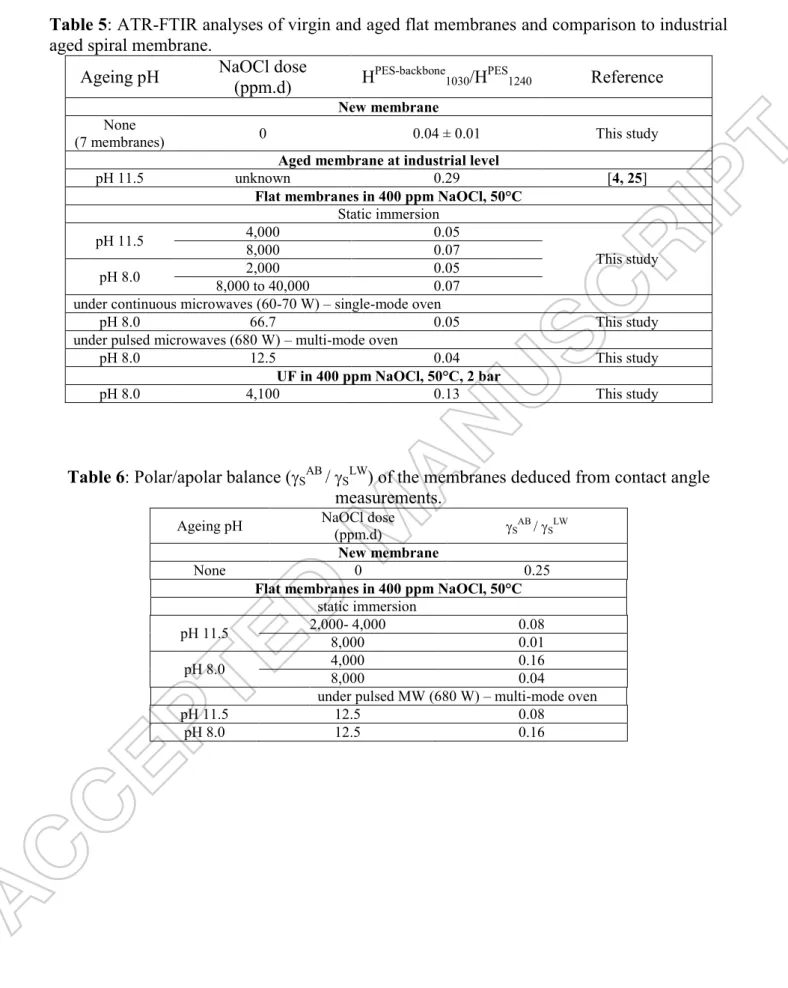
Table 5 shows the evolution of the PES backbone degradation with respect to the ageing protocols. Results confirmed that the PES backbone was much more stable than the PVP and consequently quite difficult to degrade. UF conditions allowed to evidence the PES degradation. Nevertheless trends suggested that it could also be possible, for longer and/or optimised MW treatments.
These results suggested that it could be possible to select MW degradation conditions that could be related only to PVP disappearance or to both PVP and PES degradation. This is an interesting result that could be used in the future aiming at studying the respective impact of the evolution of the two polymers on UF performances.
15
Insert Table 5 about here
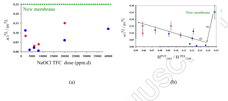
4.2.2. Contact angle and polar/apolar balance evolution. The evolution of the polar/apolar
balance is given by the SAB/sLW ratio. A decrease in this ratio means a decrease in the hydrophilic overall character of the membrane. Figure 13a depicts that the aged membranes became less polar than the new one when NaOCl dose increased up to 10,000 ppm.d, regardless of the pH in static immersion. Then the hydrophilic character increased but remained lower than that of the virgin membrane.
Attempt of correlation between the SAB/
sLW ratio and the PVP content in the membrane deduced from ATR-FTIR is shown Figure 13b.Obviously the polar/apolar character decrease can be related to the PVP departure evidenced from ATR-FTIR spectra. Roughly, experimental data obtained at pH= 11.5 and pH= 8.0 followed the same global trends. Nevertheless, some outlier data were observed at pH= 11.5 suggesting that this cannot be the single explanation.
Insert Figure 13 about here
Remembering that the PES backbone modification can increase the hydrophilic character of the aged membrane, the evolution in two times of the SAB/
sLW ratio could be in good accordance with a first rapid removal of PVP and a PES degradation starting after a sufficient NaOCl dose. Table 6 shows the evolution of the polar/apolar character of some aged membranes. These results cannot be discussed without the understanding of the previous comment.
Insert Table 6 about here
4.2.3. SEC-HPLC. Membranes aged for a long time in static immersion either at pH=11.5 or
pH= 8.0, were dissolved in CHCl3 before SEC-HPLC injection. Figure 14 shows that the
soluble fraction increased with the NaOCl dose received by the membrane, regardless of the pH. This results is in good agreement with the PES backbone evolution.
Mn, Mw and PI are shown Figure 15 for different ageing protocols. Obviously, simultaneously with the increasing amount of the soluble fraction, the characteristics of the soluble fraction evolved. Clearly, SEC-HPLC was in good agreement with the PES C-S bond cleavage, as it has been already suggested by the Cl uptake (see above, SEM-EDX).
Insert Figure 14 about here Insert Figure 15 about here 4.2. UF performances according to ageing protocols
4.2.1. Permeance to water of membranes aged by static immersion or under MW. The
membrane permeance to water was measured with respect to the membrane ageing (Table 7).
The Lpaged/Lpnew ratio variation evidenced the permeance decrease with ageing down to
40%-30% of the initial value. The permeance was close for membranes aged (1) close to 80,000 ppm.d at both pH 11.5 and pH 8.0 and (2) under pulsed micro-waves at 12.5 ppm.d at both pHs. The decrease was in good accordance with the PVP removal already mentioned above. The increase in the membrane hydrophobic character is in agreement with an increase of the overall membrane resistance to water transfer. Nevertheless no simple relationship was found
between HPVP
16 None of the tested conditions allowed to observe an increase in permeance as it was the case for the membrane aged at industrial scale. Was it due to a too short MW irradiation time or to absence of mechanical degradation in absence of UF conditions? The answer remained unclear at this moment.
Insert Table 7 about here
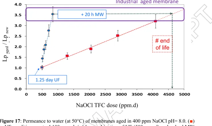
4.2.2. Permeance to water of membranes aged in UF conditions. The membrane permeance
to water (Lp) was measured for 8 flat membranes aged up to various NaOCl doses (Figure
16). Lp increased linearly up to a 2,500 ppm.d TFC dose with an excellent reproducibility.
Then the dispersion increased a little. However, the Lpaged/Lpnew ratio remained roughly linear
up to a 4,000 ppm.d dose (Figure 17). The permeance increase for this final dose was in good agreement with that estimated for the membrane aged at industrial scale from few
measurements achieved on several flat coupons of 127 cm2 aleatory sampled in the industrial
spiral membrane (Figure 17). These results were in agreement with the assumption claiming that ageing in UF conditions could be a real requirement to superimpose mechanical ageing to chemical one.
Insert Figure 16 about here Insert Figure 17 about here
4.2.3. Permeance to water of membranes aged by combination of UF and MW conditions. To
minimise the UF duration in NaOCl (with respect to the integrity of the UF pilot) combination of short UF up to 500 ppm.d dose (1.25 day) and immersion under pulsed microwaves has been tested. Simultaneously the power applied has been strongly decreased when compared to that used in the trials described above with the multi-mode oven. A power equal to 60 W has been previously shown to be efficient with the single-mode oven but this power cannot be selected with the multi-mode oven used in the present study. Finally, 170 W has been arbitrary selected because it was the lowest possible value with the multi-mode oven.
Figure 17 depicts that no permeance increase was observed after the short UF ageing. But adding short MW irradiation times (up to 20 h, 833 ppm.d dose) allowed, as expected, to increase the permeance. The degradation of both PVP and PES have been checked by ATR-FTIR for a membrane aged by a combination of short UF + 12h MW (Figure 18).
Insert Figure 18 about here
4.2.4. Rejection of lysozyme and fouling. UF of lysozyme was achieved in standard conditions
at 50°C on pristine and flat membranes aged either in UF (Figure 19a) or in static immersion with or without MW irradiation (Figure 19b). Whereas the protein rejection was full with the new membrane, ageing protocols by static immersion with or without MW induced a more or less pronounced decrease. This impact of membrane ageing on rejection was in good
accordance with industrial observations. It is well known in dairy that -lactalbumin initially
retained by the pristine membrane is able to transfer in the permeate with an aged one (generally the transmission can be increased up to 10-15% before the membrane being changed). Of course, with respect to this criterion, time under MW irradiation had to be optimised to adjust the treatment duration to the expected degradation level.
17 5. Conclusions
The present study highlights potentiality of microwaves irradiation to accelerate PES/PVP membrane ageing by NaOCl aiming at proposing a rapid ageing protocol useful at laboratory scale for further fundamental studies to improve filtration performances of aged membranes at industrial scale. Immersion of the UF membrane under pulsed MW (650 W) in deionised water have no impact on the membrane chemical degradation as checked by ATR-FTIR. On the contrary, irradiation by continuous MW (60 W, at a controlled temperature of 50°C) or by pulsed MW (650 W, with less temperature control) accelerate the degradation by NaOCl, highlighting a MW impact that cannot be only related to thermal effects of MW. The chemical degradation was followed by SEM-EDX, ATR-FTIR, SEC-HPLC and contact angle measurements with a nice agreement between all results. Nevertheless, these physico-chemical characterisations were not sufficient to conclude on the degradation representativeness when compared to ageing at industrial scale. UF performances had also to be checked and water flux as well as behaviour during UF of a model protein were determined for this purpose.
Aiming at contributing to the understanding of the relative impact of chemical and mechanical degradation, combination of a short UF step and short treatment under pulsed MW (170 W) has been studied. The combination was demonstrated to be similarly efficient as a single long UF step performed without any MW irradiation. These results suggest that mechanical degradation cannot be reached by only MW irradiation. However this assumption is in contradiction with our own more recent study highlighting that MW conditions can be found to reach the expected ageing state [29].
Regardless of this last remark, conditions using MW exist to reach ageing state representative of progressive membrane degradation at industrial scale. Of course, adjustments of at least the applied power, the irradiation duration of (pulsed) MW are required together with the control of the overall matter present in the (given) oven.
To date, we have already transposed the present study using a quite NaOCl resistant PES/PVP membrane to a less resistant one made of aromatic polyamide (RO) in order to evaluate the harmlessness of non-oxidant biocides when compared to NaOCl. Adapation of MW
irradiation conditions were required, but the general trends confirmed the interest of MW
irradiation to study the ageing or stability of other polymer membranes [30]. So the
proof of concept is done and it seems that characterisation thanks to ATR-FTIR combined to simple UF performances (water flux and rejection of a model solute) could be sufficient to go ahead.
Acknowledgements.
The authors thanks the French National Agency for Research (ANR) for the financial support during the Meduse Project (ANR-09-BLAN-0055-02) and especially to prof. Christel Causserand, coordinator of the project, for discussions.
The authors acknowledge Francis Gouttefangeas, from the CMEBA microscopy platform of the ScanMAT UMS of “Université de Rennes 1” (https://scanmat.univ-rennes1.fr/la-plate-forme-cmeba) for SEM pictures for SEM-EDX analysis of all membranes.
HAJ acknowledges the Lebanese Association for Scientific Research « LASER », the AZM association (Lebanon), Université de Rennes 1 (ISCR-CIP, ISCR and SDLM doctoral school), Lebanese University / Université Libanaise for the grants having financially supported her PhD.
18 Nomenclature section
Microwaves :
MW : micro-waves
ET : the penetration depth of MW (cm)
the wavelength of the MW (cm)
‟r : the dielectric constant of the medium
"r : the dielectric loss of the molecule
Pd : the power of MW transferred per unit volume of material
: the medium conductivity
E : the local electric field intensity of MW
ν : the MW frequency (Hz) tan δ: dielectric loss tangent
P: power delivered by the MW oven (W)
Membrane separation :
Lp0 : permeance of pristine membrane to water (L.h-1.m-2.bar-1) Lpaged : permeance of aged membrane to water (L.h-1.m-2.bar-1) J0,water : pristine membrane flux to water (L.h-1.m-2)
TMP: transmembrane pressure (bar)
VRR : volume reduction ratio = Vfeed initial/ Vfeed final (dimensionless) UF : ultrafiltration
Ageing in oxidant conditions : TFC : total free chlorine (ppm) D : dose in TFC (ppm)
NaOCldose : cumulative TFC dose (ppm.d)
ATR-FTIR characterisation :
[P]: the protein concentration on membrane (µg.cm-2)
H1240PES: the height of the band at 1240 cm-1 attributed to PES (absorbance unit)
H1539 protein amide II: the height of the band at 1539 cm-1 attributed to protein amide II band (absorbance unit)
SEC-HPLC :
Mn: apparent average molecular masses in number (g.mol-1)
Mw: apparent average molecular masses in weight (g.mol-1)
PI: apparent polydispersity index, PI = Mw/Mn (dimensionless) Contact angle measurements :
Ɵ: contact angle between the dried membrane and a given solvent(°)
S : global superficial tension of the membrane (mJ.m-2)
SLW : apolar/hydrophobic contribution to S (mJ.m-2)
SA : acid contribution to
S (mJ.m-2)
19 References
[1] Pellegrin B., Prulho R., Rivaton A., Thérias S., Gardette J.- L., Gaudichet-Maurin E., Causserand C., Multi-scale analysis of hypochlorite induced PES/PVP ultrafiltration membranes degradation. J. Membr. Sci. 2013; 447, 287-296.
[2] Pellegrin B., Gaudichet-Maurin E., Causserand C., Mechano-chemical ageing of PES/PVP ultrafiltration membranes used in drinking water production. Water Sc. Technol. 2013; 13(2), 541-551.
[3] Bégoin, L., Autopsie de membranes spirales de l‟industrie laitière- Physico-chimie du nettoyage de membranes PES d‟ultrafiltration de lait écrémé (Autopsy of spiral membranes of dairy industry. Physico-chemistry of the cleaning of PES membranes used in skim milk ultrafiltration). Report of PhD thesis of Université de Rennes 1, France, 2004.
[4] Bégoin L., Rabiller-Baudry M., Chaufer B., Faille C., Blanpain-Avet P., Benezech T., Doneva T. A., Methodology of analysis of a spiral wound module. Application to PES membrane of ultrafiltration of skimmed milk, Desalination 2006; 192, 40-53.
[5] Bégoin L., Rabiller-Baudry M., Chaufer B., Hautbois M. C., Doneva T. A., Ageing of PES industrial spiral wound membrane of acid whey ultrafiltration, Desalination 2006, 192, 25-39.
[6] Delaunay D., Nettoyage éco-efficace de membranes planes et spirales d‟ultrafiltration de lait écrémé. Approches physico-chimiques et hydrodynamiques concertées (Eco-efficient cleaning of flat and spiral membranes used in skim milk ultrafiltration. Dual approach based on physico-chemistry and hydrodynamic), Report of PhD thesis of Université de Rennes 1, France, 2007.
[7] Diallo H., Transfert de complexes métalliques en milieu acide phosphorique concentré ou dilué par membrane de nanofiltration. Application à la production de l'acide phosphorique (Transfer of metal complexes in concentrate or diluate phosphoric acid in nanofiltration. Application to phosphoric acid production), Report of PhD thesis of Université de Rennes 1, France, 2009.
[8] Wienk I. M., Meuleman E. E. B., Borneman Z, Van den Boomgaard Th., Smolders C. A., Chemical treatment of membranes of a polymer blend: mechanism of the reaction of hypochloride with poly(vinylpyrrolidone), J. Polym. Sci.: Part A: Polym. Chem., 1995; 33, 49-54.
[9] Arkhangelsky E., Kuzmenko, D. Gitis V., Impact of chemical cleaning on properties and functioning of polyethersulfone membranes, J. Membr. Sci. 2007; 305, 176–184.
https://doi.org/10.1016/j.memsci.2007.08.007
[10] Yadav K., Morison K. R., Effects of hypochlorite exposure on flux through polyethersulphone ultrafiltration membranes, Food Bioproducts Process., 2010; 88, 419-424. [11] Prulho R., Analyse multi-échelle de la dégradation de membranes polymères d'ultrafiltration au contact de l'hypochlorite de sodium (Multi-scale analysis of ultrafiltration
20 polymer membrane degradation by contact with sodium hypochlorite), Report of PhD thesis of Université Blaise Pascal, Clermont-Ferrand, France, 2013.
[12] Prulho R., Therias S., Rivaton A., Gardette J.-L., 2013. Ageing of polyethersulfone/ polyvinylpyrrolidone blends in contact with bleach water, Polym. Degrad. Stab. 2013; 98, 164–1172.
https://doi.org/10.1016/j.polymdegradstab.2013.03.011.
[13] Hanafi Y., Szymczyk A., Rabiller-Baudry M., Baddari K., Degradation of poly(ethersulfone)/polyvinylpyrrolidone membranes by sodium hypochlorite: insight from advanced electrokinetic characterizations, Environ. Sci. Technol. 2014; 48, 13419-13426. https://doi.org/10.1021/es5027882. Epub 2014 Nov 10.
[14] Hanafi Y., Loulergue P. Ababou-Girard S., Meriadec C., Rabiller-Baudry M., Baddari K., Szymczyk A., Electrokinetic analysis of PES/PVP membranes aged by sodium hypochlorite solutions at different pH, J. Membr. Sci. 2016 ; 501, 24–32.
https://doi.org/10.1016/j.memsci.2015.11.041.
[15] Loupy A. (Editor), Microwaves in Organic Synthesis, Second Edition, Wiley‐VCH Verlag GmbH & Co, Weinheim, Germany, 2008
https://doi.org/10.1002/9783527619559
[16] de la Hoz, A. (Editor) and Loupy, A. (Editor), Microwaves in Organic Synthesis, 2
Volume Set, 3rd Edition. ISBN: 978-3-527-33116-1, 57- 98, 2012.
[17] Wharton Y., Microwave Chemistry- Out of the lab and into production, Inst. Chem. Eng. EPIC 2011, 2011; symposium series 157, 117-121.
[18] Chatterjee S., Basak T., Das S., Microwave driven convection in a rotating cylindrical cavity, a numerical study, J. Food Eng. 2007; 79, 1269 -1279.
[19] Cha-um, W., Rattanadecho, P., Pakdee, W., Experimental and Numerical Analysis of Microwave Heating of Water and Oil Using a Rectangular Waveguide: Influence of Sample Sizes, Positions and Microwave Power, Food Bioprocess Technol. 2011; 11, 544-558.
[20] Nuchter M., Muller U., Ondruschka B., Tied A., Lautenschlager W., Review: microwave-assisted chemical reactions, Chem. Eng. Technol. 2003; 26, 1207 -1216.
[21] Remya N., Lin J._G., Current Status of microwave application in wastewater treatment – A review, Chem. Eng. J. 2011; 166, 797-813.
[22] Hayes B. L., Microwave Synthesis, Chemistry at the speed of Light, CEM Publishing, Matthews, NC, 2002.
[23] Diagne N. W., Rabiller-Baudry M., Paugam, L., On the actual cleanability of polyethersulfone membrane fouled by proteins at critical or limiting flux, J. Membr. Sci. 2013; 425–426, 40–47.
21 [24] Rabiller-Baudry M., Chaufer B., Aimar P., Bariou B., Lucas D., Application of a convection–diffusion–electrophoretic migration model to ultrafiltration of lysozyme at different pH values and ionic strengths, J. Membr. Sci. 2000; 179, 163–174.
[25] Rabiller-Baudry M., Bouzin A., Hallery C., Girard J., Leperoux C., Evidencing the chemical degradation of a hydrophilised PES ultrafiltration membrane despite protein fouling, Sep. Purif. Technol. 2015; 147, 62–81.
[26] Delaunay D., Rabiller-Baudry M., Gozalvez-Zafrilla J. G., Balannec B., Frappart M., Paugam L., Mapping of protein fouling by FTIR-ATR as experimental tool to study membrane fouling and fluid velocity profile in various geometries and validation by CFD simulation, Chem. Eng. Process. 2008; 47, 1106–1117.
[27] Rabiller-Baudry M., Bégoin L., Delaunay D., Paugam L., Chaufer B., A dual approach of membrane cleaning based on physico-chemistry and hydrodynamics: Application to PES membrane of dairy industry, Chem. Eng. Process. 2008; 47, 267-275.
[28] Van-Oss C. J., Forces Interfaciales en Milieux Aqueux Masson, Paris, France, 1996. [29] Rabiller-Baudry M., Thomas P., Nguyen T. K. H., Girard J. El Mansour El Jastimi M., Loulergue P., Simulation of membrane ageing to go ahead in fouling and cleaning understanding during skim milk ultrafiltration, Food Bioproducts Process. 2018; available on line
https://doi.org/ DOI: 10.1016/j.fbp.2018.10.004.
[30] Le Petit L., Rabiller-Baudry M., Touin, R., Chataigner R., Thomas P., Connan O., Périon R., Methodology for the demonstration of harmlessness of a detergent on a polyamide reverse osmosis membrane, Proceeding of Fouling and Cleaning in Food Processing Conference, April 2018, Lund, Sweden.
22 Tables
Table 1: penetration depth (ET) of MW in different solvent or materials for = 12.2 cm at 2450 MHz
Solvents / materials T(°C) ET (cm)
Water 25 1.4
Rubber 25 15 to 350
PVC 20 210
Epoxy resin (araldite CN-501) 25 4 100
Teflon 25 9 200
Porous glass 25 35
quartz 25 16 000
Table 2: Evolution of the boiling point (bp) and of the Nucleation Limited Boiling Temperature, (NLBT, under MW irradiation at 2450 MHz) of a selection of polar solvents
Solvent bp (°C) NLBT (°C) T (°C) H2O 100 104 4 EtOH 79 103 24 MeOH 65 84 19 CH2Cl2 40 55 15 CH3CN 81 107 26 Propan-2-ol 82 100 18 (CH3)2CO 56 81 25 BuOH 118 132 14 AcOEt 78 95 17
23 Table 3: SEM-EDX analyses of virgin and aged flat membranes and comparison to industrial aged spiral membrane.
Ageing pH NaOCl dose (ppm.d) Cl/S atomic ratio Reference
Aged membrane at industrial level
pH 11.5 unknown 0.033 ± 0.005 [4, 25]
Flat membranes in 400 ppm NaOCl, 50°C Static immersion
pH 11.5 8,000 0.028
This study
40,000 0.033
pH 8.0 4,000 8,000 0.024 0.033
under pulsed microwaves - multi-mode oven 680 W
pH 8.0 33.3 66.7 0.024 0.033 This study
UF in 400 ppm NaOCl, 50°C, 2 bar
pH 8.0 1,300 0.067 This study
Table 4: ATR-FTIR analyses of virgin and aged flat membranes and comparison to industrial aged spiral membrane.
Ageing pH NaOCl dose (ppm.d) HPVP
1661/HPES1240 Reference
New membrane None
(7 membranes) 0 0.15 ± 0.05
Aged spiral membrane at industrial level
pH 11.5 unknown 0.06 [4, 25]
Flat membranes in 400 ppm NaOCl, 50°C Static immersion
pH 11.5 4,000 0.14
This study
8,000 0.13
pH 8.0 4,000 8,000 0.09 0.08
under continuous microwaves (60 W) - single mode-oven
pH 8.0 33.3 0.10 This study
under pulsed microwaves (680 W) - multi-mode oven
pH 8.0 12.5 0.09 This study
UF in 400 ppm NaOCl, 50°C, 2 bar
24 Table 5: ATR-FTIR analyses of virgin and aged flat membranes and comparison to industrial aged spiral membrane.
Ageing pH NaOCl dose (ppm.d) HPES-backbone
1030/HPES1240 Reference
New membrane None
(7 membranes) 0 0.04 ± 0.01 This study
Aged membrane at industrial level
pH 11.5 unknown 0.29 [4, 25]
Flat membranes in 400 ppm NaOCl, 50°C Static immersion
pH 11.5 4,000 0.05
This study
8,000 0.07
pH 8.0 8,000 to 40,000 2,000 0.05 0.07 under continuous microwaves (60-70 W) – single-mode oven
pH 8.0 66.7 0.05 This study
under pulsed microwaves (680 W) – multi-mode oven
pH 8.0 12.5 0.04 This study
UF in 400 ppm NaOCl, 50°C, 2 bar
pH 8.0 4,100 0.13 This study
Table 6: Polar/apolar balance (SAB / SLW) of the membranes deduced from contact angle measurements.
Ageing pH NaOCl dose (ppm.d) SAB / SLW
New membrane
None 0 0.25
Flat membranes in 400 ppm NaOCl, 50°C static immersion
pH 11.5 2,000- 4,000 8,000 0.08 0.01
pH 8.0 4,000 8,000 0.16 0.04
under pulsed MW (680 W) – multi-mode oven
pH 11.5 12.5 0.08
25 Table 7: Evolution of the water permeance (Lpaged/Lpnew) of aged flat membranes and
comparison to industrial aged spiral membrane.
Ageing pH NaOCl dose (ppm.d) Lpaged/Lpnew Reference
New membrane
None 0 1.00 This study
Aged membrane at industrial level
pH 11.5 unknown (estimation) 3.5 [4, 25]
Flat membranes in 400 ppm NaOCl, 50°C Static immersion H 11.5 40,000 0.88 This study 52,800 0.30 81,200 0.30 pH 8.0 40,000 48,800 0.88 0.54 70,800 0.54
under pulsed microwaves (680 W) – multi-mode oven
pH 11.5 4.2 0.69
This study
12.5 0.43