Publisher’s version / Version de l'éditeur:
Vous avez des questions? Nous pouvons vous aider. Pour communiquer directement avec un auteur, consultez la
première page de la revue dans laquelle son article a été publié afin de trouver ses coordonnées. Si vous n’arrivez pas à les repérer, communiquez avec nous à [email protected].
Questions? Contact the NRC Publications Archive team at
[email protected]. If you wish to email the authors directly, please see the first page of the publication for their contact information.
https://publications-cnrc.canada.ca/fra/droits
L’accès à ce site Web et l’utilisation de son contenu sont assujettis aux conditions présentées dans le site LISEZ CES CONDITIONS ATTENTIVEMENT AVANT D’UTILISER CE SITE WEB.
Canadian Building Digest, 1962-01
READ THESE TERMS AND CONDITIONS CAREFULLY BEFORE USING THIS WEBSITE.
https://nrc-publications.canada.ca/eng/copyright
NRC Publications Archive Record / Notice des Archives des publications du CNRC :
https://nrc-publications.canada.ca/eng/view/object/?id=df7b268a-091b-4465-bdda-7fe942548c34
https://publications-cnrc.canada.ca/fra/voir/objet/?id=df7b268a-091b-4465-bdda-7fe942548c34
NRC Publications Archive
Archives des publications du CNRC
For the publisher’s version, please access the DOI link below./ Pour consulter la version de l’éditeur, utilisez le lien DOI ci-dessous.
https://doi.org/10.4224/40000767
Access and use of this website and the material on it are subject to the Terms and Conditions set forth at
Window air leakage
Canadian Building Digest
Division of Building Research, National Research Council Canada
CBD 25
Window Air Leakage
Originally published January 1962 J. R. Sasaki and A. G. Wilson
Please note
This publication is a part of a discontinued series and is archived here as an historical reference. Readers should consult design and regulatory experts for guidance on the applicability of the information to current construction practice.
Cracks around windows are usually the major source of the air leakage that affects so significantly the performance of buildings. Air infiltration increases the heating load in winter and may limit comfort conditions adjacent to windows; in air conditioned buildings it increases the cooling load in summer. On the other hand, it provides some or all of the outside air needed to control odours and relative humidity in buildings without mechanical ventilation, and may supply as well the air required for the combustion of fuel for heating.
Air leakage around windows also affects the performance of the windows themselves. The configuration of the air flow path is important with respect to their resistance to rain leakage and dust penetration, and with double windows largely determines the conditions under which condensation between panes will occur.
It is the purpose of this Digest to discuss the implications of window air leakage, its characteristics and criteria. Much that is said may be applied to air leakage around closed doors. Leakage through doors having a high traffic rate is especially significant and is a separate problem.
Implications of Air Leakage
In a typical air conditioned office building equipped with loose double windows (2 cfm/ft of crack at 0.30 in. water) that take up a third of the gross outer wall area, window air leakage contributes approximately 45 per cent of the wall heat gain in summer and 60 per cent of the wall heat loss in winter under design weather conditions. In the same building equipped with very tight windows (0.1 cfm/ft of crack at 0.30 in. water) window air leakage contributes approximately 4 per cent of the wall heat gain in summer and 8 per cent of the wall heat loss in winter. The proportion of the total building heat gain or loss from window air leakage depends on the building design and use. It will usually be quite a small percentage of the total cooling requirements; for example, 4 per cent with the loose windows and ¼ per cent with the tight windows referred to above. For heating the values may be 16 and 1 per cent respectively. It might be noted that design weather conditions occur infrequently and that for most of the year the percentage of the heat loss or gain from air leakage will be less than the figures referred to above.
In buildings with mechanical ventilation, window tightness need only be limited by economics, assuming that the ventilation system provides the number of air changes required to control
odour and humidity. Without air conditioning it is usually necessary to have operable windows since mechanical ventilation systems generally do not provide sufficient ventilation and air movement for summer comfort.
In buildings without mechanical ventilation window tightness may be limited by the minimum outdoor air requirement. The hourly air change required to control odours depends on the use and occupancy of the building; for houses the minimum accepted at present is about 0.3, although it is possible that slightly lower values would be acceptable to some families. This ventilation rate or greater may be required to prevent: excessive relative humidity in many houses (see CBD 1). Infiltration also, provides the furnace air requirement. For a relatively tight insulated house air needed for combustion under design weather conditions amounts to about 1/8 air change per hour; adding an equal amount for the control of chimney draft brings the total to about ¼ air change per hour.
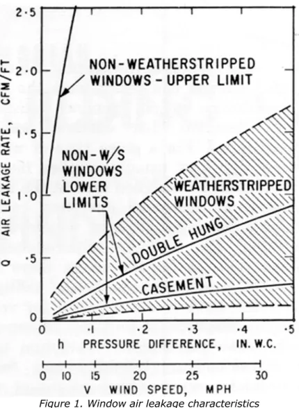
Air leakage into buildings varies markedly with weather conditions; it may provide adequate air change rates under some weather conditions and either excessive or inadequate rates under others. In a well insulated bungalow with loose windows and doors (2 cfm/ft of crack at 0.30 in. water) air infiltration can easily amount to one air change per hour and contribute up to 30 per cent of the total heat loss under design weather conditions. With very tight windows (0.1 cfm/ft of crack at 0.30 in. water) and weatherstripped doors, air leakage could be reduced to 'a air change and amount to only 5 per cent of the total heat loss under design conditions. In such a tight house it would be necessary to induce additional ventilation through open windows or other means and provide a separate air supply for combustion. Thus it is not possible on the basis of fuel economy o justify this degree of air tightness with operable windows. With the aid of weatherstripping windows available at present can provide air leakage rates down to ½ cfm per foot of crack at 0.30 inch water (Fig. 1). Such windows, with weatherstripped doors, are likely to limit house ventilation rates to 31 air change per hour under design weather conditions in most of Canada.
Figure 1. Window air leakage characteristics
In designing double windows to overcome condensation between panes the air leakage rate of the inner glazing assembly should not exceed about 0.1 cfm per foot at 0.30 inch water (see CBD 5). This is readily achieved with double glazing in a single sash where air flow between sash and frame bypasses the air space. To achieve this degree of air tightness between sash and frame while retaining ease of operation, as would be required for windows with independently operating inner and outer sash, requires an unusual quality of design. Windows of this tightness are sometimes specified by architects for air conditioned buildings or for buildings having special requirements where a custom design can be justified.
In order to appreciate fully the significance of the window air leakage values referred to above, a knowledge of the mechanism. of window air leakage and current window air leakage criteria is required.
Window Air Leakage Characteristics
Window air leakage is the flow of air around a closed sash and through a frame that results from a pressure difference across the window. Significant air leakage can also take place between the window frame and the surrounding construction; but this depends on construction details and workmanship and is not a characteristic of the window.
The relationship between air flow and pressure difference across a window can be expressed as Q = chn, where Q is the window air leakage and h is the pressure difference. The pressure
outside air temperature difference and ventilating equipment (see CBD 23). The value of the exponent, n, falls between ½ and 1 depending on the characteristics of the cracks and the pressure difference; at typical design pressure differences it is closer to ½ for units with cracks of normal width and closer to 1 for units having unusually narrow cracks. The geometry factor, c, increases as the amount or length of crack increases; the reciprocal is a measure of the window tightness or resistance to air flow.
Resistance to air flow through a given amount of crack increases as the length of path through the crack increases or as the effective crack width or clearance decreases. This clearance depends on the alignment of mating surfaces and on the effectiveness of locking devices. In general, increasing tightness results in more difficult sash operation.
The tightness of any window arrangement can usually be increased significantly by the use of weatherstripping - any material or device introduced between the sash and frame to decrease the clearance or increase the length of the air flow path without interfering with the sash operation. Weatherstripping should be capable of convenient replacement and of withstanding wear and weathering over a long period without loss of effectiveness.
In double windows having independently operating inner and outer sash the resistance to air flow depends on the tightness of both units. In order to control condensation between panes, however, it is necessary to provide essentially all the resistance to air flow at the inner unit (see CBD 5).
The air pressure difference across windows also provides the force that causes rain penetration. It is greatest across elements such as weatherstripping that provide the major resistance to air leakage, so that it is important to protect these elements from wetting by wind driven rain. With double windows this is accomplished conveniently by providing essentially all the resistance to air leakage at the inner sash. The possibility of rain penetration past the outer sash is minimized since there is no air pressure difference across it.
It has become common practice in Canada and the U.S.A. to express window air leakage rate, Q, as air flow per foot of window crack length. Crack length is determined by summing the individual crack lengths that occur wherever the operating sash contacts the frame or another sash and is based on the dimensions of the clear opening in the frame. It is usual to assume that the total air leakage for any size of window can be calculated from values of the air leakage per foot of crack obtained for a specimen of similar design. Air leakage per foot of crack, however, usually varies more or less with window size, both because different cracks in a window occur in different proportion and because pressures imposed by locking hardware vary. For a precise definition of window air leakage it is therefore necessary to describe the window dimensions; in window specifications a standard size is usually specified.
In Europe it is the practice to excess air leakage as a rate per unit area of window. Here again, it is necessary to specify the Size of window in making comparisons.
Because the factors affecting window tightness are complex, the air leakage characteristic of a window must be determined directly by test. An air pressure difference is imposed across the window and the resulting flow measured. The test apparatus consists of a pressure chamber, a window mounting panel forming one wall of the chamber, an air supply to the chamber and a flow meter. The window is mounted in the panel so that air leakage can only occur around the sash and through the frame. Double windows may be tested with the storm unit open to ensure that the inner unit alone provides the required resistance to air flow. Window air leakage measurements are usually made at pressure differences from 0.10 to 0.30 inch water column, corresponding to the stagnation pressure of wind of 15 to 25 mph, since air leakage at higher wind speeds is not of concern.
A large number of window air leakage tests have been performed in the United States, Britain and Europe. The majority of windows tested were single wood vertical sliders and casements although a number of types of aluminum, steel and wood single and double windows have been tested more recently. Typical air leakage characteristics of vertical sliding and casement
windows are summarized in Fig. 1, which shows the large variation in the tightness of non-weatherstripped windows as compared to that of non-weatherstripped windows. The advantage of weatherstripping in reducing air leakage is evident.
Window Air Leakage Criteria
The large variation in air leakage characteristics of windows clearly demonstrates the need for air leakage performance criteria. In establishing performance criteria for Canadian windows both the benefits of tight windows and the degree of tightness obtainable at reasonable cost must be considered.
Window air leakage criteria have been developing in both the United States and Norway, and are of special interest here since the climate in parts of these countries is similar to that in Canada. In Norway the Building Research Institute has published air leakage rating curves based on tests on a large number of windows, mainly wood casement, in a standard opening. Translated into air leakage per foot of sash crack at 0.30 inch water column, the maximum air leakage rates for classification as acceptable, good and excellent are 0.36 cfm, 0.19 cfm and 0.16 cfm respectively.
In the United States, separate air leakage criteria have been established for aluminum, steel and wood single windows by the respective manufacturers' associations. The following values are the maximum permissible for the various window types, in cfm per foot of sash crack at a pressure difference of 0.3 inch water column:
Aluminum Windows Vertical
sliding - standard duty cfm/ft- ¾ - heavy duty cfm/ft- ½ Horizontal
sliding - standard duty
- ¾ cfm/ft Casement - standard and heavy duty
weatherstripped
- ½ cfm/ft non-weatherstripped cfm/ft- 1 Steel
Windows - all types - 1 cfm/ft Wood
Windows - standard duty -weatherstripped Horizontal and vertical
sliding cfm/ft- ¾ Casement cfm/ft- ½,
A significant step in Canada has been the development by the Canadian Government Specifications Board of performance specifications for aluminum and sashless windows. In these specifications air leakage requirements are comparable to those listed for aluminum windows in the United States. The Canadian Standards Association has published wood window specifications that are soon expected to incorporate air leakage requirements.
Summary
Substantial savings in the heating and cooling costs of buildings can result from the use of tight windows, but in general satisfactory tightness demands that windows must be weatherstripped.
For a given type of window, increased tightness usually implies increased cost. This must be weighed against the savings resulting from decreased operating cost and the other advantages of tight windows when establishing air leakage requirements. In buildings such as houses where there is no mechanical ventilation and air infiltration provides the outdoor air required for ventilation and combustion of fuel, use of extremely tight windows can reduce ventilation to the point where odour, humidity and furnace draft problems occur. Other means of ventilation must then be introduced. This degree of window tightness is therefore greater than can be justified on the basis of fuel economy alone.
In order to minimize or eliminate the problem of condensation between panes of double windows the resistance to air flow around the inner glazing assembly must be many times that around the outer glazing assembly. It follows that in windows with independently operating inner and outer sash the resistance to air leakage should be provided entirely by the inner sash. This is consistent with good design for resistance to rain penetration as well. These implications of air leakage must be considered in the design and selection of windows in addition to the more obvious effects of over-all infiltration on a building and its occupants.