Publisher’s version / Version de l'éditeur:
Vous avez des questions? Nous pouvons vous aider. Pour communiquer directement avec un auteur, consultez la première page de la revue dans laquelle son article a été publié afin de trouver ses coordonnées. Si vous n’arrivez pas à les repérer, communiquez avec nous à [email protected].
Questions? Contact the NRC Publications Archive team at
[email protected]. If you wish to email the authors directly, please see the first page of the publication for their contact information.
https://publications-cnrc.canada.ca/fra/droits
L’accès à ce site Web et l’utilisation de son contenu sont assujettis aux conditions présentées dans le site LISEZ CES CONDITIONS ATTENTIVEMENT AVANT D’UTILISER CE SITE WEB.
Internal Report (National Research Council of Canada. Division of Building
Research), 1963-04
READ THESE TERMS AND CONDITIONS CAREFULLY BEFORE USING THIS WEBSITE. https://nrc-publications.canada.ca/eng/copyright
NRC Publications Archive Record / Notice des Archives des publications du CNRC :
https://nrc-publications.canada.ca/eng/view/object/?id=1bec96dc-0c99-4623-b3ac-7c2e35497dc5 https://publications-cnrc.canada.ca/fra/voir/objet/?id=1bec96dc-0c99-4623-b3ac-7c2e35497dc5
NRC Publications Archive
Archives des publications du CNRC
For the publisher’s version, please access the DOI link below./ Pour consulter la version de l’éditeur, utilisez le lien DOI ci-dessous.
https://doi.org/10.4224/20358536
Access and use of this website and the material on it are subject to the Terms and Conditions set forth at
Full-scale loading test on a valley and hip roof
NATIONAL RESEARCH COUNCIL CANADA
DIVISION OF BUILDING RESEARCH
FULL-SCALE LOADING TEST ON A VALLEY AND HIP ROOF
by
W. A. Dalgliesh
Internal Report No. 267 of the
Division of Building Research
OTTAWA April 1963
P R E F A C E
T h e s t r e n g t h and adequacy of roof f r a m i n g s y s t e m s in c u r r e n t u s e in Canadian houses have been t h e subjects of r a t h e r intensive s t u d i e s by t h e Division of Building R e s e a r c h . T h e need for an evaluation of t r a d i t i o n a l r a f t e r and joist roof f r a m e s a r o s e p a r t l y in connection with the r e v i s i o n of the National Building Code. T h e Building S t r u c t u r e s Section t e s t e d s e v e r a l full-scale r o o f s a s well a s individual joist and r a f t e r f r a m e s under simulated snow loads up to failure.
Valley and hip r o o f s had not been included in t h i s s e r i e s of t e s t s . In specifying valley r a f t e r and hip r a f t e r s i z e s for the Housing S t a n d a r d s 1963, t h e s e r a f t e r s w e r e s i m p l y r e q u i r e d t o b e 2 in. deeper than t h e common r a f t e r s . Calculations, m a d e t o check the adequacy of t h e r e q u i r e m e n t , showed that u n l e s s the sheathing could b e counted on for a considerable p a r t of the l o a d - c a r r y i n g capacity of t h e valley section, t h e valley r a f t e r deflections would b e excessive. It s e e m e d , t h e r e f o r e , d e s i r a b l e to obtain verification of the p e r f o r m a n c e of the valley r a f t e r b y actual t e s t , provided t h i s could b e done in the limited t i m e that r e m a i n e d b e f o r e publication of the Housing Standards. A single f u l l - s c a l e loading t e s t of a valley and hip roof was accordingly c a r r i e d out t o evaluate t h i s unknown element in i t s s t r u c t u r a l action.
. T h e t e s t was planned jointly b y H. J. T h o r b u r n and
W. A. Dalgliesh, R e s e a r c h Officers in t h e Building S t r u c t u r e s Section. After t h e d e p a r t u r e of H. J. T h o r b u r n f o r post graduate s t u d i e s in England, W. A. Dalgliesh was r e s p o n s i b l e for the execution of the t e s t and t h e completion of this r e p o r t under t h e direction of W, R. S c h r i e v e r , Head of t h e Section.
Ottawa, April 1963
R o b e r t F. Legget, Director.
FULL-SCALE LOADING TEST ON A VALLEY AND H I P ROOF
by
W. A. Dalgliesh
T h e Housing Standards 1963, now Supplement No. 5 to the National Building Code of Canada, r e q u i r e that hip and valley r a f t e r s b e 2 in. deeper than t h e corresponding common r a f t e r s and that, in addition, r i d g e support b e provided in the hip o r valley
section where a t i e cannot b e m a d e between opposite r a f t e r ends. Calculations w e r e m a d e t o check the adequacy of t h i s r e q u i r e m e n t . In t h e s e p r e l i m i n a r y calculations, the s t r e n g t h of the roof f r a m i n g m e m b e r s only (i. e. without the sheathing) was c o n s i d e r e d ; the uniform load on the jack r a f t e r s was a s s u m e d t o b e divided equally between the valley r a f t e r and t h e r i d g e beam. T h i s approach indicated that the bending moment in t h e valley r a f t e r
might b e a s much a s 5 to 10 t i m e s g r e a t e r than in the common r a f t e r in which c a s e t h e 2-in. i n c r e a s e in depth for the valley r a f t e r would b e inadequate.
It was thought, however, that the valley portion of a roof s y s t e m might d e r i v e an additional. amount of s t r e n g t h and s t i f f n e s s f r o m the sheathing, an e f f e c t which is difficult to evaluate theoretically,
i n view of the m a n y complications caused by the yielding of nailed
connections in an actual roof. Consequently, i t was decided to d e t e r m i n e the t r u e s t r e n g t h of a hip and valley roof, due t o both "framing action" and "sheathing action,
"
by conducting a load t e s t on a f u l l - s c a l e roof. Since t h e r e was only a limited period of t i m e within which a change t o the valley r a f t e r r e q u i r e m e n t s could s t i l l be m a d e in the Housing Standards, only one s i m p l e t e s t was c a r r i e d out.DESCRIPTION O F ROOF
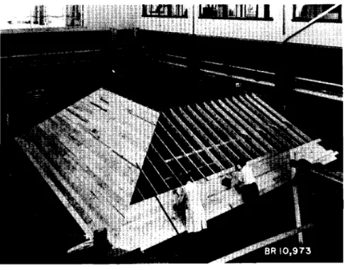
An L-shaped roof 28 by 28 ft in plan, with 24-ft s p a n s and 5/12 s l o p e s was constructed in s t r i c t a c c o r d a n c e with the Housing Standards 1963 ( F i g u r e s 1 and 2). R a f t e r s , joists and r i d g e b e a m s w e r e 2 by 6 in. except for the hip and valley r a f t e r s which w e r e
2 by 8 in. At 4-ft i n t e r v a l s , 2- by 4-in. r i d g e s u p p o r t s w e r e provided in the valley section, and knee ,walls w e r e used in place of c o l l a r t i e s w h e r e t h e jack r a f t e r s w e r e too s h o r t t o i n s t a l l a collar t i e a t the mid-point of the r a f t e r span. A l l m e m b e r s w e r e No. 1 (construction)
E a s t e r n Spruce, except f o r t h e sheathing which was No. 2 E a s t e r n S p r u c e and Pine.
T h e p r i m a r y p u r p o s e of t h e t e s t was t o d e t e r m i n e the s t r u c t u r a l action and whether t h e valley r a f t e r would deflect unduly under load; consequently, only the valley, hip and four common r a f t e r s w e r e i n s t r u m e n t e d for deflection readings. In addition, pencil l i n e s w e r e m a r k e d a c r o s s v a r i o u s joints t o indicate whether movement would
t&ke p l a c e during loading.
T e n deflection gauges w e r e used: 5 on the valley r a f t e r , 1 each on t h e c e n t r e of t h e hip and t h e 4 common r a f t e r s ( F i g u r e 3). After each load application, deflection r e a d i n g s w e r e m a d e by a s u r v e y o r ' s l e v e l s e t up outside t h e roof.
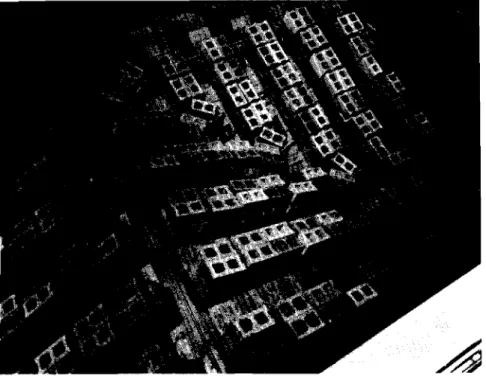
T h e load consisted of 8-in. c o n c r e t e blocks applied over the e n t i r e roof s u r f a c e i n l a y e r s consisting of 216 blocks each. Spaces w e r e left between r o w s of blocks to prevent a r c h i n g of t h e load a s the roof deflected. Blocks in the f i r s t l a y e r averaged 47. 5 l b each, while a l l o t h e r s a v e r a g e d 40 lb. B e c a u s e each block contributed load t o an a r e a (on t h e horizontal) of 3. 55 s q ft, t h e f i r s t l a y e r gave a uniform loading of 13. 4 psf, while succeeding l a y e r s added 11. 3 psf each ( F i g u r e 4).
Supports w e r e s e t up under t h e roof s e p a r a t e d f r o m the s t r u c t u r e by gaps of a few inches w h e r e and when they w e r e considered n e c e s s a r y , a s a safeguard against complete collapse of t h e roof under t h e dead weight method of loading used.
OBSERVAT I ONS
T a b l e I l i s t s t h e loads and corresponding deflections of t h e
valley, hip and common r a f t e r s . Generally, the r o o f behaved " e l a ~ t i c a l l y ' ~ up t o 40 psf, but a s the downward deflection of the valley r a f t e r i n c r e a s e d , jack r a f t e r s began t o pull away f r o m the N-S r i d g e b e a m on t h e valley side. As t h e r i d g e beam was supported by kingposts i t could not move downwards with the valley r a f t e r and consequently e i t h e r t h e jack-to -valley r a f t e r connection o r the jack-to-ridge beam connection would have t o
s e p a r a t e ; the s e p a r a t i o n o c c u r r e d at 45 t o 50 psf a t the jack-to-ridge connection.
J a c k r a f t e r s Nos. 2 and 3 ( F i g u r e 3) in the hip section a l s o seemed to be rotating upwards with r e s p e c t to the hip r a f t e r at a load of 45 to 50 p s f .
At a load of 55 to 60 p s f the pulling away of the jack r a f t e r s on the west side of the N-S ridge had increased to a maximum of 3/4 in. At 70 psf the middle portion of the N-S ridge beam ( a 2 by 6) could
be seen bowing slightly to the east. The jack r a f t e r s on the west
side had slipped downwards, and the sheathing had a pronounced bow in the middle ( F i g u r e 7).
Two rows of blocks had been added around the bottom, two rows laid a t the top on the e a s t side of the N-S ridge, and one row completed on the west side of the N-S ridge at the top when failure occurred by slippage of the jack r a f t e r s down the ridge beam. T h e average load over the roof at this t i m e was 70 to 75 psf ( F i g u r e 5).
The r a f t e r s , in the c e n t r a l region especially, on the west side of the N-S ridge had pulled down and out f r o m the ridge. A support was built to catch t h e s e r a f t e r ends and loading was continued up to
80 to 85 psf ( F i g u r e 6). Because i t appeared that t h e r a f t e r ends were moving towards the ridge t o thrust against i t in bearing, the support was removed, readings taken, and then loading was continued.
Before long the north r a f t e r s on the E-W ridge began t o pull away and the roof s u r f a c e began t o settle. Loading was stopped
immediately and blocks w e r e removed t o leave a load of 70 p s f on the roof over the weekend.
Measurements taken on the following Monday showed that r a f t e r s on the west side of the N-S ridge had dropped in some places a s much a s 4 1/4 in. vertically down the ridge at the connection but s t i l l were t h r u s t -bearing on the ridge for a length of 1 1/4 in. ( F i g u r e s 7, 8). This was t r u e of r a f t e r s Nos. 5 and 6 ( F i g u r e 3). R a f t e r s Nos. 1 t o 4 were not bearing but were separated from the ridge by amounts varying from 3/4 in. at r a f t e r No. 1 t o 1/8 in. at r a f t e r No. 4. R a f t e r s Nos. 7 t o 12 ( F i g u r e 3) had shifted downwards by p r o g r e s s i v e l y l e s s e r amounts, and w e r e bearing on the ridge except for r a f t e r s Nos. 10 and 11 which were 1/4 in. f r o m the ridge.
A s i m i l a r situation was found on the north side of the E-W r a f t e r , where r a f t e r s Nos. 2 t o 8 ( F i g u r e 3) had slipped about 4 in. leaving 1 t o 2 in. of bearing on the ridge ( F i g u r e
9).
RESULTS
J a c k r a f t e r s began t o s e p a r a t e f r o m the N-S r i d g e b e a m along t h e w e s t s i d e a t 45 t o 50 psf. At 70 t o 75 psf s o m e of t h e r a f t e r s pulled completely f r e e of the r i d g e b e a m , causing a sudden s e t t l e m e n t of the sheathing; f a i l u r e can b e s a i d to have been r e a c h e d , although complete c o l l a p s e did not occur a t t h i s point. As loading continued, t h o s e r a f t e r s which had pulled f r e e dropped back onto t h e N-S r i d g e b e a m , 2 o r 3 in. below t h e i r o r i g i n a l positions. Loading was stopped a t 80 t o 8 5 p s f a f t e r r a f t e r s on the n o r t h s i d e of the E-W r i d g e had begun t o p u l l away f r o m t h e r i d g e b e a m and t o t a l c o l l a p s e of the roof s e e m e d imminent.
T h e m o s t i m p o r t a n t r e s u l t was that t h e deflections e x p e r i e n c e d by t h e v a l l e y and hip r a f t e r s w e r e not r e a l l y e x c e s s i v e when c o m p a r e d t o t h o s e of t h e four i n s t r u m e n t e d common r a f t e r s ( F i g u r e 9 ) . T h e upper end of t h e v a l l e y r a f t e r was pushed downwards a t o t a l of 0. 9 in. a t t h e r i d g e ; only n e t deflections ( f r o m a s t r a i g h t l i n e joining the ends of the r a f t e r s ) which r e p r e s e n t the v e r t i c a l component of the a c t u a l m o v e m e n t s of t h e gauge points a r e given in F i g u r e
9.
DI SCUSSI ON O F RESULTS
In t h e f i r s t a n a l y s i s of t h e f r a m i n g s y s t e m in t h e valley a r e a , the jack r a f t e r s w e r e c o n s i d e r e d t o span a s s i m p l e b e a m s between the r i d g e and t h e valley r a f t e r . Half t h e load c a r r i e d by e a c h jack r a f t e r was a s s u m e d t o b e t r a n s f e r r e d t o t h e valley r a f t e r which would have caused e x c e s s i v e deflections at working loads.
T h e f u l l - s c a l e t e s t showed that no such e x c e s s i v e deflections o c c u r r e d a t working loads. T h e unexpected s t i f f n e s s of the valley s e c t i o n a p p e a r e d t o be provided by t h e combined action of the sheathing,
jack r a f t e r s and t h e v a l l e y r a f t e r in spanning between t h e h e e l and the peak in the valley s e c t i o n , and can p r o b a b l y b e explained a s follows:
T h e v a l l e y section c o n s i s t e d e s s e n t i a l l y of two right-angled t r i a n g l e s joined along t h e i r hypotenuses by t h e valley r a f t e r . T h e two p l a n e s m e t a t t h e f a i r l y f l a t angle of 148 deg. Sections at r i g h t angles t o t h e valley r a f t e r w e r e V-shaped and varied in depth f r o m 0 ft a t e i t h e r end t o a m a x i m u m of 2 1/3 ft.
As load w a s applied t o t h e p l a n e s of t h i s V-shaped "beam, " p a r t of i t was t r a n s m i t t e d through t h e jack r a f t e r s t o the v a l l e y r a f t e r which deflected v e r t i c a l l y downwards. T h i s caused s t r e s s t o b e applied
in the planes of t h e roof and t h e r e l a t i v e l y high stiffness of t h e s e planes apparently prevented e x c e s s i v e deflection of the valley
r a f t e r . T h e valley section thus acted somewhat like a single-folded plate, the action of which can be visualized a s t h a t of two inclined
deep b e a m s joined together along a bottom "seam. T h e s e two b e a m s b y their interaction w e r e loaded in-plane and gave mutual l a t e r a1 support to each other t o p r e v e n t out -of -plane bending.
The fact that t h e sheathing was continuous back into the gable s e c t i o n s m a y have helped t o c a r r y s o m e of the load into the common r a f t e r s a s well, but i t s e e m s probable that a m a j o r portion of the load was borne d i r e c t l y by the valley section a s d e s c r i b e d above.
CONCLUSIONS
T h e f u l l - s c a l e loading t e s t , c a r r i e d out on a n L-shaped valley-and-hip r o o f , indicated that t h e valley r a f t e r used in the t e s t was able to m a t c h sufficiently the s t r e n g t h of the common r a f t e r s although neither r e a c h e d f a i l u r e . T h i s showed that the original assumption about the strength and stiffness of the valley section of the r o o f , based on the f r a m i n g action only, had been too p e s s i m i s t i c .
T h e deflections of the hip r a f t e r w e r e s m a l l a s expected. T h e deflections m e a s u r e d a t the mid-point of the hip r a f t e r w e r e slightly l e s s than the deflections of the common r a f t e r s .
In conclusion, i t can b e stated that the L-shaped valley-and- hip r o o f tested with a v e r t i c a l l y supported ridge, showed a load
-
c a r r y i n g capacity c o m p a r a b l e t o that of a s t r a i g h t roof of the s a m e type of r a f t e r and joist construction. No m e m b e r s failed in the t e s t ; the weak link in the s t r u c t u r e proved t o b e t h e toe-nailed connection of the r a f t e r s t o the r i d g e beam.T A B L E I
LOAD - D E F L E CTION DATA
Net V e r t i c a l M i d - P o i n t D e f l e c t i o n s , in. Net D e f l e c t i o n s of V a l l e y R a f t e r , in. Load p s f 1 3 25 36 47 59 70 7 5 8 1 8 5 Hip e 0. 22 0. 37 0 . 5 7 0. 7 5 0 . 9 0 1. 12 1. 16 1. 43 1. 67 Load p s f 1 3 25 3 6 47 5 9 70 7 5 8 1 8 5 R e m a r k s B e h a v i o u r m a i n l y e l a s t i c J a c k - t o - r i d g e joint opening N e a r - f a i l u r e of r o o f r e a c h e d V a l l e y c 0. 16 0. 36 0 . 5 6 0 . 8 7 1. 23 1. 8 4 2. 1 5 2. 49 2. 7 4 C o m m o n R a f t e r s G a u g e P o i n t f 0. 17 0. 33 0 . 5 1 0 . 7 3 0 . 9 3 1. 30 1. 42 1. 58 1. 70 a 0. 07 0. 17 0. 27 0. 41 0. 56 0 . 8 5 0. 92 1. 07 1. 20 g 0. 22 0. 35 0 . 5 2 0 . 7 4 0 . 9 5 1. 33 1. 4 3 1. 6 4 1. 7 5 b 0. 16 0. 3 4 0. 5 3 0. 8 3 1. 15 1. 79 1. 99 2. 29 2. 58 h 0 . 0 5 0. 30 0 . 4 5 0 . 6 5 0 . 8 5 1. 26 1. 46 1. 8 4 2.06 c 0. 16 0. 36 0. 56 0. 87 1. 23 1. 8 4 2. 1 5 2. 49 2. 7 4 k 0. 1 4 0. 25 0 . 3 9 0. 56 0. 71 1. 00 1. 0 4 1. 42 2. 44 d 0. 13 0. 29 0. 47 0. 7 3 1. 00 1. 61 1 . 8 3 2. 05 2. 31
LEVEL 0
D E - F L E C T I O N G A U G E S M A R Y E P A To
6
PLAN
\IIE.ld
ofq O O F
84 2 8 8 5
-
2F l G U Q L
3
F i g u r e 4 Loading p r o c e d u r e f o r v a l l e y a n d h i p r o o f t e s t
Figure 5 70-to 75-psf load caused failure of rafter along the N-S ridge (top of picture)
F i g u r e
6
F u r t h e r loading t o 80 t o 85 psf i n c r e a s e d r a f t e r movement along t h e N S r i d g e shown and a l s o caused a s i m i l a r f a i l u r e of t h e n o r t h r a f t e r joints along the E-W
r i d g eF i g u r e 7 Sheathing r e m a i n e d bowed even a f t e r unloading b e c a u s e the r a f t e r s had t h r u s t against the r i d g e beam and wedged t h e r e a t 8 0 - to 85-psf load
F i g u r e 8 Two s h e a t h i n g b o a r d s r e m o v e d ; n o t e t h e p o s i t i o n of t h e r a f t e r e n d s a f t e r a downward d i s p l a c e m e n t of up t o 4 1/4 in.
0 - 5 1.0 1-5 2.0
2.5
3.0 V E q T I C A L M / D P O I N T D E F L E C T I O N I N I N C M L S I II / '
*-
i
I
-
-
i
-
-
i
-
-
i
-
-
i
-- /
HIP
4 A F T e R
-
-
I I I I A 0 0- 5
1.01.5
2.0 2.5 V E q T . MIDPOINT DEFLECTION /N /rllCtl&So
a 5 1 . 01.5
2 . 02 . 5 3.0
O -5 1.01.5
2.0 2.5V E Q T I C A L M I D p O I N J DEFLECTION V & g T . MIDPOINT DEFLECTION
IN I N C H E S I N I N C M E S