HAL Id: hal-02115524
https://hal-amu.archives-ouvertes.fr/hal-02115524
Submitted on 30 Apr 2019
HAL is a multi-disciplinary open access
archive for the deposit and dissemination of
sci-entific research documents, whether they are
pub-lished or not. The documents may come from
teaching and research institutions in France or
abroad, or from public or private research centers.
L’archive ouverte pluridisciplinaire HAL, est
destinée au dépôt et à la diffusion de documents
scientifiques de niveau recherche, publiés ou non,
émanant des établissements d’enseignement et de
recherche français ou étrangers, des laboratoires
publics ou privés.
DEMO design using the SYCOMORE system code:
Influence of technological constraints on the reactor
performances
Cédric Reux, Sébastien Kahn, L. Zani, Bernard Pégourié, N. Piot, Michal
Owsiak, Giacomo Aiello, Jean-Francois Artaud, Arthur Boutry, Saied
Dardour, et al.
To cite this version:
Cédric Reux, Sébastien Kahn, L. Zani, Bernard Pégourié, N. Piot, et al.. DEMO design using the
SYCOMORE system code: Influence of technological constraints on the reactor performances. Fusion
Engineering and Design, Elsevier, 2018, 136, pp.1572-1576. �10.1016/j.fusengdes.2018.05.059�.
�hal-02115524�
DEMO design using the SYCOMORE system code: In
fluence of technological
constraints on the reactor performances
C. Reux
a,⁎, S. Kahn
a, L. Zani
a, B. Pégourié
a, N. Piot
a, M. Owsiak
e, G. Aiello
b, J.-F. Artaud
a,
A. Boutry
a, S. Dardour
c, L. Di Gallo
a, J.-L. Duchateau
a, D. Galassi
a,d, F. Imbeaux
a, J.-C. Jaboulay
b,
P. Magaud
a, J. Said
a, B. Saoutic
a, P. Sardain
aaCEA, IRFM, F-13108 Saint-Paul-lez-Durance, France
bCEA, DEN, Saclay, DM2S, SERMA, F-91191 Gif-sur-Yvette, France cCEA/DEN/DER/SESI/LEMS, F-13108 Saint-Paul-lez-Durance, France
dAix-Marseille Université, CNRS, Centrale Marseille, M2P2 UMR 7340, 13451 Marseille, France ePoznan Supercomputing and Networking Center; IChb PAS, Noskowskiego 12/14,61-704 Poznan, Poland
A R T I C L E I N F O Keywords: DEMO System code Fusion reactor Breeding blankets Superconducting magnets Tritium Tritium Power balance A B S T R A C T
The next step for fusion energy after the ITER tokamak is the demonstration power plant DEMO. In this fra-mework, system codes are used to address high-level key design issues for the DEMO pre-conceptual phase. They aim at capturing the interactions between the subsystems of a fusion reactor. SYCOMORE is a modular system code which includes physics and technology models coupled to an optimizer in order to explore a large design parameter space. In the present paper, trade-off studies focused on technology modules are reported including the influence of some design-driving assumptions on the reactor performances and size, starting from a European DEMO1-like design (more than 500 MW net electric power and 2 h burn duration). The increase of the me-chanical stress limits in TF and CS magnets can help reducing the reactor size, slightly more when high tem-perature superconductors are used in the TF coil. The tritium breeding ratio can be improved to more than 1.10 by a moderate increase of the size, but the tritium burn-up ratio needs one additional meter of major radius for every percent increase. Divertor coolant options are also compared, showing some differences between helium, hot and cold water scenarios at various incident divertor heatfluxes.
1. Introduction
The next step for fusion energy after ITER is the design and building of a demonstration power plant usually called DEMO. Design trade-offs must therefore be made to ensure that the primary goals of such a re-actor are met. System codes aim at providing a global view of a fusion power plant by describing all its susbsytems using simple engineering models and scaling laws. One important feature of system codes is the ability to capture interactions between subsystems: design choices made on one subsystem may affect all the others. Such a method en-sures the consistency of the design result. Fusion power plant design usually involves both plasma physics and fusion technology modelling. Thefinal performance of the reactor depends as much on the plasma as all the technological elements supporting it: superconducting magnets, tritium breeding blankets and tritium systems, plasma facing compo-nents, thermodynamical power conversion systems. The present con-tribution explores the influence of the performances of these
subsystems on the reactor global performances and size through the use of the SYCOMORE system code.
2. The SYCOMORE system code 2.1. General description
SYCOMORE is a modular system code developed at CEA-IRFM for DEMO design. It contains a suite of plasma and technology modules addressing DEMO designs as well as an optimizer allowing the user to specifyfigures of merit and constraints on the outputs or inputs of the calculation. A complete description of the content of the modules can be found in[1]and[2].
2.2. Relevant technology modules
SYCOMORE has been recently upgraded with technology-oriented
⁎Corresponding author.
modules. Their description is given below. 2.2.1. Superconducting magnets
The toroidalfield (TF) Coil module updated version used in SYC-OMORE aims to stand the best representation of the TF magnet inner leg radial build. In a general way the TF extended representation usually includes compliance with TF design criteria such as temperature margin, hotspot temperature and mechanical stress limits both on jacket and casing. In thefirst version of the module[3]most of them were considered while in the present version all are included. The de-scription of the TF magnet also includes considerations of turns stacking optimization in the casing winding housing, representing for both conductor jacket and casingfinite radii for corners. The inputs taken from the SYCOMORE workflow to build the TF section are the TF inner leg outermost side position, the TF total current and the major radius. Together with the classical design criteria (temperature margin, hotspot maximum temperature, Tresca stress upper limit, maximum ground voltage during discharge) the casing minimum thickness is also im-posed. In the present study, two designs options are proposed: a Low Temperature Superconductor (LTS) Nb3Sn similar to the one used in
European DEMO studies, and a generic high temperature super-conductor (HTS). The generic HTS is based on REBCO-like character-istics (critical current formula, temperature margin, quench detection time) as described in [4]. The real geometry of the HTS conductor (tapes instead of strands) is ignored in the present study: the LTS cable geometry is kept for the HTS study. The goal of such a rough assump-tion is to assess the performance gains (or machine size reducassump-tion) provided by a potentially higher toroidalfield. The detailed design of the HTS coils within a system code is left for future studies. More details on the module and its validation can be seen in[4].
2.2.2. Tritium systems
Tritium breeding blankets are mainly modelled from the neutronics point of view. The neutronics module uses a surrogate model composed of neural networks trained against 2D and 3D neutronics calculations. Using a simplified geometrical model of the reactor, it computes the tritium breeding ratio and energy multiplication factor as a function of the fusion power and geometric features of the reactor. The blanket coverage is 88% in the module, with the divertor occupying the re-maining 12%. Heating and access ports are left out of the TBR calcu-lation but taken into account in the total thermal power recovered by blankets. The TBR calculated by the module does not take. A more complete description can be found in[5,1].
2.2.3. Particleflux balance
This module computes the input and output particlefluxes (deu-terium D and tritium T) for plasma fuelling (mainly through cryogenic pellets) and pumping. The tritium burn-up (D-T fuel consumption rate over total tritium injection rate) is the main output of the module. The method is based on the one presented in[8,9].
The D/Tflux released by the plasma between ELMs (ΓDTdiff) is
com-puted using an effective cylindrical transport model, assuming that deuterium, tritium and helium have the same diffusion coefficients
= f f ρ ρ Γ Γ log 1/ log 1/ DT diff He DT He He DT
With fXandρXbeing respectively concentrations of fuel species and
corresponding deposition location along the minor radius. The helium flux ΓHeis defined by ΓHe= Pfus/Efus.
The D/T particleflux released by the ELMs is estimated from the fraction of the power conducted through the separatrix released by the ELMs αELMPsep, the pedestal particle Nped and energy Wped density:
ΓELM=αELMPsepNped/Wped.
The D/T particleflux is then used to define the particle flux to inject with highfield side (HFS) ice pelletsΓDTHFS pel=ΓDTdiff+ΓELM. In addition,
the maximum divertor heat capacity is used to define a minimal ELM frequency. The energy released by ELMs is defined according to results reported in[10]and[11]. The NGS pellet ablation model[12]is used to define the smallest pellet size with large enough penetration to fuel the plasma (NminHFS) and space constraints for the curvature of the pellet
injection tube are considered following[13]. The HFS pellet frequency is defined asνHFS=Γ /N
DT HFS pel
minHFS. If this frequency is smaller than the
minimal ELM frequency, lowfield side pellets are used to trigger the ELMs and the corresponding particleflux is computed. Finally, a di-vertor pumping efficiency is considered to take into account recycling in the divertor. In the studies shown in the present article, a pumping efficiency of 0.01 was assumed.
2.2.4. Power conversion systems
The power conversion system models the various coolant loops in the reactor using thermodynamical calculations described in[14,15]. This model only computes the various heatflows in the cooling circuits taking as inputs the total thermal power recovered by blankets and divertor. Neutronics parameters (energy multiplication factor) are handled by the neutronics module described in Section 2.2.2. Heat transfer loops from blankets and divertor are modelled by a heat source, a pump plus its pressurizer or a compressor depending on the chosen coolant and a heat sink. Breeding blankets are helium-cooled in the present version, whereas divertor can be cooled with either water or helium. Both heatsinks for divertor and blankets are connected to a Rankine water cycle for power conversion. Two turbines (high and med/low pressure) are used for power conversion. The minimum and maximum temperatures in the divertor and blanket cycles are given as user inputs, and chosen to reflect the current technologies for water (PWR reactors) and helium cycles. The pressure distribution in the various cycles is also given as afixed input following current technol-ogies. Pressure drops in the divertor and blanket cycles are not yet calculated consistently, as this would require the detailed cooling channel geometry in the divertor or blanket circuits. It would increase the computation time beyond what is required for a system code. Such a calculation is currently in development for the first wall cooling channels of the HCLL blanket model, but is left for future work. Divertor and blanket cycles are then connected to the power conversion Rankine cycle. Its efficiency is computed as a function of the temperature at the steam generator outlet and a pressure distribution given by the user and optimized on a typical DEMO reactor. Depending on the operation temperature of a water cooled divertor, its heat can be used for Rankine steam cycle preheaters or reheaters instead of high grade heat to the steam generator.
2.2.5. Plasma facing components
Plasma facing components are treated in SYCOMORE with their maximum allowed heatflux. The heat flux on the divertor is computed by an edge plasma physics model. Macroscopic limits for the peak heat flux limit (max(Qpeak)) are used as a proxy for the technology chosen for
the divertor. More details on the edge plasma physics model can be found in[1]or[6].
3. Results
3.1. Starting design point
The starting design for this study is a DEMO1-like optimization problem: find the smallest machine in terms of major radius with 500 MW net electric power and 2 h burn duration. Optimization vari-ables are the major and minor radii, the toroidal magnetic field on plasma axis and the density-averaged plasma temperature. Constraints are summarized inTable 1. The optimization procedure uses a genetic algorithm described in[16]. In all the subsequent results, all these constraints are always simultaneously fulfilled thus giving a consistent integrated design.
3.2. Toroidalfield superconducting magnets: LTS vs. HTS, influence of maximum steel stress
In order to assess the influence on the design performances of the maximum allowed stressσmax,TFon the steel jacket of the toroidalfield
magnets, the smallest possible designs satisfying DEMO1-constraints for a range ofσmax,TFwere determined. The range forσmax,TFwas chosen
deliberately wide, including very high values, to explore a parameter space in which the maximum allowed stresses are no longer the limiting design factor. This space is believed to favor HTS which can withstand higher maximumfields on the conductor. It is acknowledged that no present-day cryogenic steels able to reach these stress exist but this is only an exploratory study which is one of the purposes of system codes. The results are given inFig. 1. The temperature margin and quench detection delay for LTS and HTS are respectively 1.5 K/3.0 s and 10 K/ 15.0 s.
Compared to the baseline DEMO1-like constraint around 650 MPa, increasingσmax,TFto values up to 900 MPa can yield a gain of approx
30 cm on the radius of the reactor. The gains tend to saturate with σmax,TFvalues above 1000 MPa. Using HTS yields around 10 cm gain on
the reactor size forσmax,TFvalues above 800 MPa. This is explained by
the larger sensitivity of LTS to the increased effective field on the conductor Beff(more superconducting material is needed) compared to
HTS. The gain is moderate due to the fact that Beffis on overall quite
low and thus far from the region where HTS show significant differ-ences from LTS. More advanced or compact designs at higher Btmight
be different and are left for future investigations.
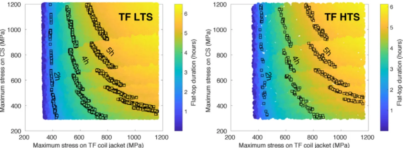
At fixed reactor size, increasing σmax,TF can allow longer burn
durations as shown inFig. 2. 5 h could be reached if bothσmax,TFand
σmax,CS limits were increased to 800 and 600 MPa respectively. The
difference between TF LTS and TF HTS is again very moderate, but could provide additional benefits if HTS were used in the CS. 3.3. Tritium breeding ratio, tritium burn-up
The evolution of the reactor size to meet DEMO1 constraints for a range of TBR values is given inFig. 3. Every point represents the highest TBR which can be reached for a given size of the machine, or in other words, the smallest machine for a given TBR.
Increasing the TBR from 1.05 to 1.11 only needs a 25–30 cm major radius increase, with only slight signs of saturation above 1.10. The compactness at low TBR values is only partly due to the reduction of the inboard breeding zone thickness. The TF coil is indeed brought closer to the plasma thanks to the thinner breeding zone, thus requiring lower field on the coil then less steel.
Tritium-related constraints also include the burn-up ratio. Although no hard minimum is set, this ratio determines the size of the tritium plant needed to process the tokamak exhaust gas. A too low burn-up would lead to unacceptably high tritium inventories in the plant. SYCOMORE was used to determine by how much the burn-up ratio can be increased by system-level considerations namely by varying the iterations variables described in Section 3.1, i.e. not changing the plasma scenario.Fig. 4shows that adding one percent burn up needs approximately 1.0 m additional major radius. Reaching 3% burn-up with the constraints described inTable 1therefore needs a 11.5 m re-actor. The main part of the burn-up improvement is due to the increase of the fusion power with the size. Increasing the toroidalfield is another route to increase burn-up, but is less favorable in terms of net electric power due to the higher powerflux on the divertor.
3.4. Divertor coolant
Starting from the DEMO1-like case, three coolant options (helium, 325 °C water and 155 °C water) at 3 different maximum heat fluxes (as proposed for example in [7]) on the divertor were explored.Fig. 5
shows the smallest possible design for the three different maximum heat fluxes. It shows that Helium or hot (PWR-level) water are equivalent in term of reactor size. The additional pumping power re-quired for helium is almost compensated by the increased divertor cycle efficiency, and any difference would be small anyway, given the low fraction of the total thermal power (200 MW out of 2000 MW) received by the divertor. Going to lower water temperatures (for instance due to heatflux constraints) leads to a larger device to be able to meet the 500 MW Pnetconstraint. The reactor size is nonetheless equivalent for a
5 MW m−2hot water design and a 10 MW m−2cold water design. The fact that all three coolant choices are close to each other for the 15 MW m−2constraint can be attributed to lower fusion power needed to fulfill the constraints and therefore lower conducted power to the divertor, shrinking the difference between the various coolant choices. 4. Conclusion
The impact of technological constraints on the performances and size of a pulsed DEMO1-like reactor (Pnet> 500 MW and
Δ(tburn) > 2 h) were explored using the SYCOMORE system code.
Increasing the mechanical stress limit on TF magnets can yield several tens of cm from the baseline 650 MPa point but tend to saturate above 1000 MPa. The size reduction is slightly better for high temperature superconductors at high mechanical stresses. Atfixed major radius, the burn duration can also be increased by 2–3 h thanks to an increase of mechanical stress limits on both TF and CS coils. The tritium breeding ratio can be increased from 1.05 to 1.11 by a 25 cm major radius in-crease but also tends to saturate for higher values. Conversely, the
burn-Table 1
Starting point– DEMO1-like constraints.
Figure of merit Minimize R Optimization variables R, a, B0, Te ne
Constraints
Pnet > 500 MW
Flat-top duration > 7200 s δ95,κ95 0.33, 1.59
Safety factor at 95%flux 3.5 Greenwald fraction 1.2
H-factor 1.1
NBI current drive efficiency 0.35 × 10²⁰×〈T e〉
Max. heatflux on divertor 10 MW m−2 Tritium breeding ratio 1.10 Neutronflux on TF coil 1013n.m−2.s−1
Number of TF coils 16 Max. stress on TF coil jacket 650 MPa Max. stress on TF coil vault 650 MPa Max. stress on CS coil 400 MPa
Fig. 1. Smallest DEMO1-like reactor for a range of maximum stresses allowed on the TF steel, with corresponding maximumfield on the TF conductor.
up fraction is much more difficult to improve from the reactor design perspective: Each 1% gain needs an additional meter on the major ra-dius. For a DEMO1-like design, helium and hot water are almost equivalent in terms of net electric power, the additional pumping power required being compensated by the better efficiency of the cycle. Cold water divertor conversely leads to larger design to meet the constraints. These studies show the importance of integrating as many technological constraints as possible in system codes to benefit from their ability to capture potentially counter-intuitive trade-offs between subsystems.
References
[1] C. Reux, et al., DEMO reactor design using the new modular system code SYCOMORE, Nuclear Fusion 55 (June) (2015) 7.
[2] C. Reux, et al., DEMO design using the SYCOMORE system code: conservative as-sumptions and pathways towards the reactor, Proceedings of the 26th IAEA FEC Conference, Kyoto, Japan, 2016 October.
[3] J.-L. Duchateau, et al., Conceptual integrated approach for the magnet system of a tokamak reactor, Fusion Eng. Des. 89 (11) (2014) 2531–2556.
[4] L. Zani, et al., Development and applications of magnets module for SYCOMORE CEA system code, presented at SOFE 2017 Conference, to be published in Transaction on Plasma Science (2017).
Fig. 2. Evolution of burn duration by varyingσmax,TF. Left: LTS. Right: HTS.
Fig. 3. Smallest DEMO1-like reactor for a given TBR request. Left: corresponding inboard breeding zone thickness. Right: corresponding radius of the outermost side of the inboard leg of the TF coil.
Fig. 4. Smallest DEMO1-like reactor for a number of different burn-up targets.
Corresponding net electric power as a colorscale. Fig. 5. Smallest DEMO1-like reactor for a range of divertor coolant scenarios.
[5] J.-C. Jaboulay, et al., Neutronic predesign tool for fusion power reactors system assessment, Fusion Eng. Des. 88 (9–10) (2013) 2336–2342.
[6] D. Galassi, Investigating heatflux imbalance in the complex geometries of fusion devices and assessing simplified models as guide lines to code understanding and pre-design tools for reactors, Università Di Bologna, 2013 (Master thesis). [7] J.-H. You, et al., A review on two previous divertor target concepts for DEMO:
mutual impact between structural design requirements and materials performance, Nuclear Fusion 55 (2015) 11.
[8] A.R. Polevoi, et al., Assessment of pumping requirements in ITER for pellet fuelling and ELM pace making, Proceedings of the 35th EPS conference on plasma physics, Hersonissos, Greece, 9–13 June 2008. ECA Vol. 32 (2008) P-1.109.
[9] A.S. Kukushkin, et al., Physics requirements on fuel throughput in ITER, J. Nucl. Mater. 415 (2011) S497.
[10] T. Eich, et al., Divertor power deposition and target current asymmetries during
type-I ELMs in ASDEX upgrade and JET, J. Nucl. Mater. 363–365 (2007) 989. [11] T. Eich, et al., Type-I ELM power deposition profile width and temporal shape in
JET, J. Nucl. Mater. 415 (2011) S856.
[12] P.B. Parks, R.J. Turnbull, Effect of transonic flow in the ablation cloud on the lifetime of a solid hydrogen pellet in plasma, Phys. Fluids 21 (1978) 1735. [13] P.T. Lang, et al., Considerations on the DEMO pellet fuelling system, Symposium on
Fusion Technology, San Sebastian, Spain, 2014 October.
[14] Y.A. Cengel, M. Boles, Thermodynamics: An Engineering Approach, 4th ed., McGraw-Hill Science/Engineering/Math, 2001 ISBN: 0-0725-4904-1. [15] S. Dardour, Development of an Energy Conversion Module for the SYCOMORE
Platform, CEA Nuclear Energy Division Internal report, 2013.
[16] L. Di Gallo, et al., Coupling between a multi-physics workflow engine and an op-timization framework, Comput. Phys. Commun. (2016 March).