HAL Id: hal-01537626
https://hal.archives-ouvertes.fr/hal-01537626
Submitted on 25 May 2020
HAL is a multi-disciplinary open access
archive for the deposit and dissemination of
sci-entific research documents, whether they are
pub-lished or not. The documents may come from
teaching and research institutions in France or
abroad, or from public or private research centers.
L’archive ouverte pluridisciplinaire HAL, est
destinée au dépôt et à la diffusion de documents
scientifiques de niveau recherche, publiés ou non,
émanant des établissements d’enseignement et de
recherche français ou étrangers, des laboratoires
publics ou privés.
Elastic-strain distribution in metallic film-polymer
substrate composites
G. Geandier, P.-O. Renault, E. Le Bourhis, P. Goudeau, D. Faurie,
Christophe Le Bourlot, Ph. Djémia, Olivier Castelnau, S. M. Chérif
To cite this version:
G. Geandier, P.-O. Renault, E. Le Bourhis, P. Goudeau, D. Faurie, et al.. Elastic-strain distribution in
metallic film-polymer substrate composites. Applied Physics Letters, American Institute of Physics,
2010, 96 (4), pp.1-3. �10.1063/1.3293450�. �hal-01537626�
Elastic-strain distribution in metallic film-polymer substrate composites
G. Geandier,1 P.-O. Renault,1 E. Le Bourhis,1,a兲 Ph. Goudeau,1 D. Faurie,2 C. Le Bourlot,2 Ph. Djémia,2O. Castelnau,2and S. M. Chérif2
1Laboratoire de Physique des Matériaux, Université de Poitiers, UMR 6630 CNRS, SP2MI-Téléport 2-Bd
Marie et Pierre Curie, B.P. 30179, 86962 Futuroscope-Chasseneuil Cedex, France
2
Laboratoire des Propriétés Mécaniques et Thermodynamique des Matériaux, Université Paris13, UPR 9001 CNRS, 93430 Villetaneuse, France
Synchrotron x-ray radiation was used for in situ strain measurements during uniaxial tests on polymer substrates coated by a metallic gold film 400 nm thick deposited without interlayer or surface treatment. X-ray diffraction allowed capturing both components elastic strains and determining how these were partitioned between the metallic film and the polymeric substrate. For strains below 0.8%, deformation is continuous through the metal-polymer interface while above, the onset of plasticity in the metallic film induces a shift between film and substrate elastic strains.
Understanding the mechanical behavior of nanostruc-tured thin films in relation to their microstructure is of ut-most importance for the development of technological applications.1At nanometer length scales, mechanical prop-erties are significantly altered.2The processes responsible for these changes are not fully understood yet and are believed to be caused by grain-surface and grain-boundary volumes becoming dominant over the bulk. In a film, changes are further caused by boundary conditions at the free surface and interfaces.1,2 Mechanical failure of metallic stiff thin films attached to a compliant polymeric substrate poses a significant challenge in the development of integrated structures such as flexible and stretchable electronics. Me-chanical behavior studies of metallic thin films deposited onto polymeric substrates mainly focused on rather large deformations.3,4In order to enhance the adhesion of the me-tallic film, either the substrate surface is activated by an oxy-gen plasma,5,6 or an adhesion layer is deposited onto the polymer substrate with strongly reactive metals such as Ti, Cr, and Al.7,8Generally, the authors supposed that the inter-face is strong enough to assume that deformation 共in the elastic regime兲 is continuous through either the substrate-film interface or the interfaces within multilayers. Both from the fundamental and applicative points of view, it is of utmost importance to clarify this question. Elastic behavior can be studied by x-ray diffraction 共XRD兲.9,10 High intensity syn-chrotron x-rays allow characterizing small volumes of mate-rial in a time schedule acceptable for in situ loading.7,11Tests were generally carried out loading uniaxially a film-substrate composite, the film being stressed biaxially because of the mismatch between the Poisson’s ratios of either the film and the supporting substrate7,11or the different sublayers.12 Mul-tiphase materials are a key area of study for diffraction-based stress or strain measurement techniques. Polymer-matrix composites have been avoided because of the difficulty in obtaining accurate diffraction data from a hydrogen-containing material. The development of synchrotron x-ray techniques offers exciting possibilities for such composite materials. Hence, we demonstrate that synchrotron XRD can
be used to monitor with accuracy both polymeric substrate and metallic film elastic strains during in situ mechanical loading.
X-ray lattice strain measurements were carried out on a laminate composite formed by a polycrystalline gold film deposited by physical vapor deposition onto a polyimide substrate from Du Pont de Nemours 共registered trademark Kapton®兲. These were 127.5 m thick and 14⫻6 mm2 in
size dog-bones cleaned with ethanol before deposition. Gold films were deposited using ion-beam sputtering. Growth chamber base pressure was 7.10−5 Pa while working
pres-sure during film growth was 10−2 Pa. Deposition was carried out at room temperature with an Ar+ ion beam at 1.2 keV.
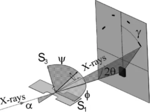
Films thickness was 400⫾10 nm while a strong 兵111其 fiber texture was obtained.13The dog-bone samples were gripped by a Deben™ tensile tester loaded uniaxially from 0 to 25 N 共macroscopic stress applied to the substrate-film composite from 0 to 33 MPa兲, unloaded to 9 N and reloaded up to 35 N 共macroscopic stress 46 MPa兲 before complete unloading. Noticeably, a threshold load of 8 N is to be applied in order to prevent sample displacements that may affect the diffrac-tion strain data. Diffracdiffrac-tion experiments have been carried out on BM02 beamline at the European Synchrotron Radia-tion Facility共ESRF, Grenoble, France兲. X-ray diffracted sig-nal was recorded by a MAR133 charge-coupled device 共CCD兲 detector placed at 120 mm from the sample and per-pendicular to the incoming beam共Fig.1兲. During the
experi-ment, the diffraction signal was recorded every 12 s 共4 s exposure time and 8 s readout兲 while the displacements of the sample surface were recorded every 30 s with a CCD camera placed above the tensile tester. The x-ray beam en-ergy was set at E = 20 keV 共=0.061992 nm兲 which is the beamline optimum for photon flux. XRD images were ana-lyzed using FIT2Dsoftware14 to obtain classical 2-intensity
diagrams integrated with a step of 1° along ␥ 共see Fig.1兲.
Digital optical image correlation has been carried out by
DEFTAC software using four different areas taken on optical images of the sample surface.
The XRD pattern of polyimide substrate obtained on a Seifert diffractometer 共Cu radiation, =0.154 nm, E = 8.04 keV, not shown here兲 displays three main character-istic reflections 共2= 15, 22.5, 27°兲 revealing its
semicrystal-a兲Author to whom correspondence should be addressed. Electronic mail: [email protected].
line nature, i.e., a mixture of crystalline and amorphous phases. Related peaks under synchrotron radiation 共E = 20 keV兲 are obtained at smaller 2 angles and stopped by the beamstop 共Fig. 1兲. Figure 2 shows the x-ray intensity measured from both the coated and the bare polyimide sub-strates on synchrotron beamline. For the coated sample, we obtain an intense peak attributed to gold while another one appears at smaller 2. Latter one is similar to that detected for the uncoated polyimide sample and is attributed to the substrate. Hence, using XRD we are able to monitor both film and substrate responses and extract respective strains fitting both peaks by Pearson VII functions. Changes in in-terplanar spacing dhkl can be used with Bragg’s law
= 2dhklsin to determine the elastic strain through the change in the Bragg’s scattering angle
= ln
冉
ddhkl 0冊
= ln
冉
sin0sin
冊
. 共1兲In the present experiment, reference state 共d0,0兲
corre-sponds to unloaded state. Strain results can then be converted into stress using a suitable stiffness value. Since diffraction is inherently selective and therefore based toward a particular set of grains, the peak shifts can be exploited for multiphase materials to provide information about strain or stress states of individual phases separately. It is important to note that XRD strains for polyimide are obtained for crystalline zones only. Hence, as mentioned above complementary optical
measurements were carried out to determine the macroscopic strains that consider both crystalline and amorphous zones.
With a two-dimensional 共2D兲 detector, strain measure-ments for several directions 共,兲 are available in a single exposure.15 Figure 3 shows the strain evolution for two 共,兲 positions for gold 共film兲 and one 共,兲 position for polyimide. The position at 90°共i.e., ␥= 0°, Fig.1兲
corre-sponds to the direction perpendicular to the tensile axis. Due to the much smaller intensity of the polyimide diffraction peak, substrate x-ray strain data are more scattered共variance ⬃5⫻10−4兲 than gold ones 共variance ⬃8⫻10−5兲. Despite the
scatter, Fig.3clearly demonstrates that both strain evolutions for gold film and Kapton®substrate can be measured accu-rately for small applied deformations. We observe for gold opposite signs for strains determined along ␥= 70° and 0°, namely, tension and compression, respectively, as expected from Poisson’s effect. Upon unloading, the strains recover elastically. Both evolutions at ␥= 0° 共measured directions 共= 90° ,⬃5°兲 close to each other兲 are very similar for the film and substrate. However, there is a small but noticeable change in the evolution of the strain in the two materials between the two cycles. Indeed, gold film and Kapton® sub-strate strains for the same共,兲 position are identical during the first cycle. Looking more carefully at the second cycle 共obtained under larger macroscopic stresses, e.g., 46 MPa versus 33 MPa兲, we can detect that the x-ray elastic strain is slightly larger in the substrate than in the film, this phenom-enon being emphasized at the end of the cycle. To improve the observation of this phenomenon, we smoothed the poly-imide data averaging over 5 consecutive points with an achieved strain resolution better than 5⫻10−4共taken as twice
the variance ⬃2.5⫻10−4兲. The key factor in achieving such a strain resolution is the superior statistics obtained with the use of both high intensity synchrotron radiation and 2D de-tector. In summary, the strain is transmitted unchanged through the film-substrate interface during the first cycle. Both the crystalline zones in the polyimide substrate and the gold thin film behave elastically and identically within the experimental uncertainty. During the second cycle 共under larger stresses兲, the responses deviate from each other be-cause of the onset of plasticity in the gold film, only the elastic strains being monitored. Noticeably, Böhm et al.7 re-port a yield stress of 500 MPa for similar deposited gold films which corresponds to the level of stress expected at the maximum of the second loading cycle.
FIG. 1. Sketch of the experiment showing the loaded specimen, the 2D detector, the incident x-ray beam, and the diffracted beam at Bragg’s angle 2.is the angle between the specimen surface normal S3and the diffract-ing plane normal,the rotation angle of the specimen around its surface normal, S1is the direction of load application,␥is the rotation angle around the detector surface normal. The Beamstop position is shown on the detec-tor.␣is the incident beam angle共␣= 9°兲.
13 14 15 16 17 5000 10000 15000 20000 2θ (°) Bare substrate Coated substrate
FIG. 2. XRD patterns of the bare Kapton® 共square symbol兲 and gold-Kapton®composite共gray circles兲 in the region of the 兵111其 gold peak using synchrotron radiation共E=20 keV兲.
0 50 100 150 200 250 300 -0.004 -0.002 0.000 0.002 0.004 Time (min) Kapton,γ= 0° Gold,γ= 70° Gold,γ= 0°
FIG. 3. X-ray strains for gold film and Kapton®substrate for different共,兲 directions共i.e., different␥angles兲 as a function of time. Black open circles and bold line are for gold at␥= 70° and 0°, respectively. Gray squares are for Kapton®at␥= 0°.
X-rays only interact with the crystalline part of the sub-strate and inform on the strain in crystalline zones. There-fore, an optical technique was used to determine the macro-scopic strain which considers both crystalline and amorphous components of the substrate. Figure4shows the evolution of the optical longitudinal strain in the plane 11 and of the macroscopic stress applied to the film-substrate composite. It can be observed that the strain follows a linear evolution as the applied stress. The strain evaluated by the optical method 共longitudinal 11兲 can be usefully compared to that obtained
by XRD 关e.g., 共␥= 70°兲兴. The obtained ratio 11/共␥ = 70°兲⬃2.5 is determined to be constant over the experiment carried out in the elastic domain indicating that crystalline and amorphous zones deform elastically and similarly.
The above results show that we can consider that defor-mation is continuous through the metal-polymer interface in a film-substrate composite loaded uniaxially in its elastic do-main 共namely, for both components兲. This is an important result since some authors recommend the use of an interlayer in order improve the adhesion between a film and a substrate of different nature.7,8We reveal that the Au-polyimide inter-face sustains elastic strains with a continuity of the deforma-tions being observed. From the fundamental point of view, this result has also important implications since the modeling of the coated substrate 共without interlayer兲 is much
simpli-fied considering a laminate formed by the film and the substrate.11,13
The elastic strain partition in a metallic film-polymeric substrate laminate has been studied by synchrotron XRD that allows monitoring the elastic responses of both components. No intermediate interlayer between the gold film and the Kapton®substrate has been used to improve adhesion. How-ever, we showed that there is a complete strain transfer through the film-substrate interface as long as the elastic do-main is scrutinized.
The authors gratefully acknowledge the European Syn-chrotron Radiation Facility for provision of beamline, as well as the staff of BM02共D2AM兲 beamline.
1M. A. Meyers, A. Mishra, and D. J. Benson,Prog. Mater. Sci. 51, 427 共2006兲.
2E. Arzt,Acta Mater. 46, 5611共1998兲.
3S. P. Lacour, S. Wagner, Z. Huang, and Z. Suo,Appl. Phys. Lett. 82, 2404 共2003兲.
4Y. Xiang, T. Li, Z. Suo, and J. J. Vlassak,Appl. Phys. Lett. 87, 161910 共2005兲.
5M. Hommel and O. Kraft,Acta Mater. 49, 3935共2001兲.
6D. L. Pappas and J. J. Cuomo,J. Vac. Sci. Technol. A 9, 2704共1991兲. 7J. Böhm, P. Grüber, R. Spolenak, A. Stierle, A. Wanner, and E. Arzt,Rev.
Sci. Instrum. 75, 1110共2004兲.
8M. K. Ghosh and K. L. Mittal, Polyimides: Fundamentals and
Applica-tions共Marcel Dekker, New York, 1996兲.
9V. Hauk, Structural and Residual Stress Analysis by Non Destructive
Methods: Evaluation, Application, Assessment共Elsevier Science,
Amster-dam, 1997兲.
10I. C. Noyan and J. B. Cohen, Residual Stresses: Measurements by
Diffrac-tion and InterpretaDiffrac-tion共Springer, New York, 1987兲.
11P.-O. Renault, E. Le Bourhis, P. Villain, Ph. Goudeau, K. F. Badawi, and D. Faurie,Appl. Phys. Lett. 83, 473共2003兲.
12N. A. Mara, D. Bhattacharyya, R. G. Hoagland, and A. Misra,Scr. Mater.
58, 874共2008兲.
13D. Faurie, P.-O. Renault, E. Le Bourhis, and Ph. Goudeau,J. Appl. Phys.
98, 093511共2005兲.
14A. Hammersley, S. Svensson, and A. Thompson,Nucl. Instrum. Methods
Phys. Res. A 346, 312共1994兲.
15G. Geandier, P. O. Renault, S. Teat, E. Le Bourhis, B. Lamongie, and P. Goudeau,J. Appl. Crystallogr. 41, 1076共2008兲.
0 50 100 150 200 250 300 0.000 0.004 0.008 0.012 0.016 0 10 20 30 40 50 Time (min) Optical strain Applied stress
FIG. 4. Macroscopic stress applied to the substrate-film composite and mac-roscopic共true兲 longitudinal strain 11as a function of time.