HAL Id: hal-01181003
https://hal.inria.fr/hal-01181003
Submitted on 28 Jul 2015
HAL is a multi-disciplinary open access
archive for the deposit and dissemination of
sci-entific research documents, whether they are
pub-lished or not. The documents may come from
L’archive ouverte pluridisciplinaire HAL, est
destinée au dépôt et à la diffusion de documents
scientifiques de niveau recherche, publiés ou non,
émanant des établissements d’enseignement et de
A Multi-View Co-Modeling and Co-Simulation
Framework for Heterogeneous Embedded Systems
Amani Khecharem, Robert de Simone
To cite this version:
Amani Khecharem, Robert de Simone. A Multi-View Co-Modeling and Co-Simulation Framework for
Heterogeneous Embedded Systems. [Research Report] Inria Sophia Antipolis. 2015. �hal-01181003�
A Multi-View Co-Modeling and
Co-Simulation Framework for
Heterogeneous Embedded Systems
Amani Khecharem
∗1and Robert de Simone
†21
Univ. Nice-Sophia Antipolis, CNRS, UMR7271, I3S F-06900
Sophia Antipolis
2
INRIA, F-06902 Sophia Antipolis
July 28, 2015
Abstract
The design of embedded platforms for connected objects (smartphones and beyond) is made harder because such systems must satisfy strin-gent constraint beyond functional correctness and accuracy. Namely, extra-functional requirements such as performance, power consumption and thermal dissipation are equally important, while there are important trade-offs between them. In the recent years so-called virtual platform-based design has been proposed, so that rather abstract models of func-tional and extra-funcfunc-tional views could be applied, together with applica-tion models seen as task graphs with performance and memory require-ments, to simulate global system dynamics before hardware was actually built. While a truly based Model Driven Engineering approach, tools and methods from this methodological area were seldom used in the pro-cess, which mainly consist of SystemC multiform simulation in practice. But, increasingly, dedicated domain-specific simulation tools, appear in the landscape, and the way to combine them properly for co-simulation becomes a true issue. It is our belief that joint multi-view modeling is key as the co-modeling approach to occur prior to co-simulation. This is all the more true as the various views/aspects here meant to be co-simulated are not distinct components of a system, as one generally assume, but distinct facets of a same component. For instance in our case a SystemC simu-lator may be found to extract abstract execution traces (or uns) from a generator program, traces which will be further annotated and decorated in the other distinct extra functional view ranges (performance, power, temperature), whose results may in turn impact the forthcoming rest of the trace. We provide a multiview modeling framework, and then show as an example how to connect it with a real (co)-simulation tool such as Synopsys Platform Architect MCO.
Keywords— Multi-view modeling, MDE, Synopsys Platform Architect MCO,
IEEE-42010, Co-simulation
∗Univ. Nice-Sophia Antipolis, CNRS, UMR7271, I3S F-06900 Sophia Antipolis †INRIA, F-06902 Sophia Antipolis
1
Introduction
Embedded systems are characterized by dealing with strict non-functional con-cerns, such as heat dissipation, energy consumption, safety and time perfor-mance. These concerns are modeled and analyzed by experts of specific domains. Experts have their own languages and tools to describe the system model from their point of view. Nevertheless, these expert’s models are strongly connected in our approach through the goals of system modeling and global engineering encompassing all aspects. The behavior of a model could impact the behavior of the other ones. Powering a component off in a model that describes power concerns, affects the functional behavior of the component in a functional de-scription model. Also, Excessive temperature in specific spots of a chip may lead to activity slow-down, or migration of tasks on different processors. The ele-ments of each expert’s domain are redefinitions of eleele-ments from other domains without conserving a consistence relationship between them.
In order to manage the structural and behavioral consistency among various expert’s models of a single system, architects propose to represent them in views [1].To this goal, views maintain their consistency by using correspondences, a syntax and semantic association between the expert’s domain elements.
The behavior specification of a view is the combination of various kinds of behavior. For instance, the power consumption of a component could be rep-resented by a Finite State Machine (FSM) [2]. Each state expresses a specific power mode, e.g., dynamic or static power consumption. However, to calculate the power consumption in a power mode, an equation need to be defined in each state. Therefore, according to this behavior description, there is a com-bination of two types of behavior: discrete event (FSM) and continuous time (equation evaluation). A well-known issue is that when assembling a continuous model with a discrete one (and even two discrete ones with distinct simulation policies), care must be taken for adaptive methods to combine the different dynamics (simulation steps may not coincide). Whether it is the duty (and the opportunity) to sample continuous values and construct meaningful timed events (state changes) on either side of the interface is a matter of debate that is often context-dependent. Indeed, it depends on the functionality of the local simulator, if distinct co-simulation is attempted, or on the off-line adjustment of distinct simulation constraints, if single global simulation is meant.
Ad-hoc techniques for join simulation of functional and extra-functional as-pects of chip design have been developed, mostly, in the context of SystemC [3] and SystemC-AMS [4], but they often lack the abstraction and orthogonality of concerns that allows reuse and modularity. On the other hand, co-simulation and co-modeling concerns can be found in the principles behind the FMU/FMI [5] and IP-XACT [6] standards, respectively. But they pay little attention to the case where distinct models are actually distinct facets/views of the same object, our goal here.
Model-Driven Engineering MDE [7] provides elements to specify specific do-main models. These models are expressed by an explicit language known as Domain-Specific Modeling Lan- guage (DSML)[8]. A DSML contains a syntax and structural semantics defined by a meta-model. This language also define an execution semantics that is usually specified in natural language or transforming the structure definition into executable code or models. Nevertheless, natural language is ambiguous in its interpretation, and transformations do not
guaran-tee that the wished behavior in the DSML corresponds to the target behavior. Moreover, the combination of various kinds of behavior is difficult to achieve following these approaches.
Our Multi View Approach proposed in this paper is a DSML that expresses the structure and and behavior of a system through views. This language pro-vides a framework where experts design their domains, abstracting their con-cepts to build a specific point of view of the system.
The contents of this paper is organized as follows. First, we present vari-ous approaches associated with co-modeling and co-simulation and motivate our approach in Section 2. Then, in section 3, we introduce the multi view model-ing approach we propose. Section 4 details each of the view domain model as well as the inter-view associations. Afterwards, we show, in Section 5 how to connect our multi view modeling framewok with Synopsys Platform Architect MCO tool. Finally, we give some conclusions in Section 6.
2
A Co-Modeling and Co-Simulation Framework
There are specific challenges involved in the design of mobile connected objects (such as smartphones and tablets, but also many others). In addition to func-tional correctness, real-time performance aspects may be requested for multi-media or communications (while “real-time" does not mean “always faster", but quite on the opposite “just as fast as to met deadlines"). Energy consumption is also an issue (because of autonomous battery powering, as is temperature level because of contact with human body or other sensible textures). Of course these topics are also requirements in the range of desktop and server computers, but solutions found are in general of a different nature.
The need for predicting functional and extra-functional evolutions “at some level of accuracy" early in the design phase led to the promotion of so-called vir-tual platforms, that are basically simulation models in which one attempts to include representation of all aspects aforementioned. This may result in a com-pound simulation model (usually written in SystemC [3], or rather assembled from SystemC component pieces put together), or more recently be attempted as a combination of two or more cooperative simulation engines. The latter approach is usually prompted by the fact that thermal simulation of floorplan models is rather different in nature from original SystemC [3] purpose of digital IP block modeling.
Now, while much attention is given to efficient (early) co-simulation, the topic of front-end co-modeling framework is usually dealt with in a rather ad-hoc informal way. The issue of proper model coupling, while admittedly a rather academic concern, is still an important one. While there are emerging standards for assembling SystemC components (IP-XACT [6]) or combining several simulators in a multi-physics co-simulation framework (FMU/FMI 2.0 [5]), they say little or nothing about the nature of the distinct models and of their interaction, at least in an intelligible and explicit modeling way. Furthermore, the FMU/FMI formalism is to the best of our knowledge always used in a case where the distinct simulators are invoked to represent distinct components (or subsystems) of a larger complex system. Here we are in a case where we want to co-simulate different aspects (or views) of the same system, and so the role of consistency between the trace path being followed by simulators is key in the
process.
To get a glimpse of the general issue, consider the following scenario: a given high-level model of some application use case, meant to represent a typical usage of the device in a relevant period (say in a day) is provided as a task graph; some initial trace may be extracted from it (which consists of selecting a single run out of a potential generative program). This trace is passed on to a model of the execution platform, where it is mapped to the hardware resources according to the current global configuration (this amounts to an abstract role of the projected Operating System). The mapped trace can then be simulated for performance with the current clock speeds, provided cost functions for elementary operations have been characterized on this architecture. Then power update can also be computed for this (now timed) trace given the power modes of various components (some may be turned off if not needed). Finally the impact of this timed and power consuming trace on the temperature (and the heat diffusion across the dye) can be simulated by a last simulation engine. Of course power consumption may in fact depend on temperature, clock processor speeds may be set up from remaining power budget, and the task mapping to hardware may depend also on all these many parameters (in addiction to be imposed possibly by the application). But in the event-based simulation tradition, effects of a given simulation "slice"are only taken into account at the next scheduling decision point, even if it may consist of undoing the last step because some value went out of bounds (temperature too hot, or power below zero for instance). In a way, to co-simulation issue here borrows the same features as the simple concurrent event-driven simulators already had to cope with.
Building a full-fledged co-simulation environment based on the premises of the previous example would certainly be very ambitious, and perhaps inefficient. Our current goal is more modestly to better understand what are the require-ments for a corresponding co-modeling framework, where distinct model views could each be clearly and orthogonally introduced first, in a modular fashion, and only then related according to their physical interactions.
The modeling will start from a backbone representation of the basic archi-tectural execution platform (which will indeed motivate the word "platform"), a bit like boards on a rack. The backbone is thus a structural block diagram representation of IP blocks, interconnects, and typical device components. Each view will be organized roughly in the same same uniform way: it will consist of a structural part, providing the modeling elements on which to build the
be-havioral part, that describe how changes occur in the view configuration, and
under which causes. The separation allows modularity and reuse, since the structural view parts are in a sense supposed to be abstract version of real physical elements later deployed on the realized object, while the behavioral part may be more subject to change in order to attempt different strategies (or simply be obfuscated in a simplified simulation plan, with some decisions being user-provided, for sake of simulation efficiency).
Concerning the structural part of views: performance view will introduce a partition of the blocks into clock domains, with nominal frequency ranges;
power view will introduce power domains, again a partition of the block diagram
backbone view, with activity levels (off, idle, active,...) and consistency rules between them; thermal view provides an abstract floorplan (again a partition of ...), with rectangular coordinate and diffusion rules between them. Finally,
the application view will provide links to which task/communication could be executed on which IP block/interconnect. In each view one is thus left with (discrete) control variables, encompassing the possible configurations of that view.
The behavioral part of views, on the other hand, prescribes how the these control values will be assigned and modified, as dynamic simulation goes along. We shall generally call such transition descriptions Application/Clock/Power/ Thermal Management Units (AMU, CMU, PMU, TMU), to recall the relation to their implementation deployed counterparts. The AMU can be thought of as an abstract vision of firmware, more specifically Operating System mapping and schduling functions. The transitions of *MUs will be triggered by explicit events from inside the system, either user-defined (if the application is meant to force some power or performance mode, or generated from (usually continuous) variables measuring physical quantities: temperatures at the defined location points in the floorplan of the thermal view, battery level, ... Those physical values are themselves correlated according to physical laws, which shall form the last ingredient of our co-modeling framework: thermal view physical values may be related to power value (as a processing resource may consume more power according to its temperature), performance values may be linked to power (as computing faster means consuming more power).Those physical relations are often acyclic, in terms of the Modelica formalism, in the sense that they are undirected (one can compute temperature from power or vice-versa). The top-level major connection between views is the one linking the application view to the architecture backbone one, computing task and communication mapping in presence of clcok, power, thermal level information. Even though it could be presented as other inter-view relations for sake of (rather fake) symmetry, it is in fact highly algorithmic and cyber in nature. It could be made arbitrarily complex, and the exact strategies in existing mobile devices is usually kept secret by constructors. Even though our main objective was to describe a clean and explicit co-modeling environment to allow precise co-simulation of joint multi-view systems, we shall refrain at that stage from proposing a modeling solution here (it could be fixed by an adequate SystemC power-thermal-aware OS description).
Last year in a FDL paper [9]ed some attempts at linking a preliminary ver-sion of such a co-modeling framework to abstract simulation tools such as Scilab (for thermal modeling) and our own tool CCSL/TimeSquare for application scheduling. In the current paper we go one step beyond by providing a two-fold transformation scheme which translates both the application view and the back-bone platform (basic) view into Synopsys MCO Platform Architect models, in a way that can easily be extended to encompass performance and power views (still under development), and also be connected with external tools (such as Scilab [10] or Docea Power AcePlorer [11]) for thermal modeling (as prototyped in [12]). Again the difficulties met to realize in practice the "global picture" show the intrinsic complexity of the assembly methods, but we are truly convinced that establishing a clear "view-component"-based setting for representation of such complex virtual platforms is a key step in the proper understanding and reuse of the multi-view co-simulation methodology approach.
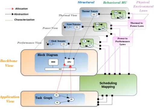
Figure 1: Multi-View Approach
3
An MDE Multi View Modeling Approach
3.1
Architecture description
The design of a system needs to take into account different concerns. Such system concerns comprises reliability, performance, cost, temperature or power consumption. These concerns require different types of point of views since they rely on various facets of the system (power, thermal, etc.). Thus, the main purpose of multi-view modeling is to build full-fledged models of a system from several points of view while ensuring consistency among system concerns.
The ISO/IEC 42010 [1] is a standard that introduces, analyses and relates concepts such as architectural description which contains four essential concepts:
Viewpoint, View, Correspondence and Correspondence Rule. According to the
standard, a Viewpoint is a way of looking at a system; the View is composed of models determined by the viewpoint. The Correspondence specifies the view relation with the semantics defined by Correspondence Rules.
3.2
Multi-View approach
We apply the multi-view approach to predefine rules and elements that can de-scribe and coordinate different views of a system. More precisely, based on a system backbone, our approach allows defining specific views that are focused on the control of its non-functional properties. Hence, experts from various domains can build a system from their own point of view (time performance, power, temperature, etc.) while maintaining the system consistency by
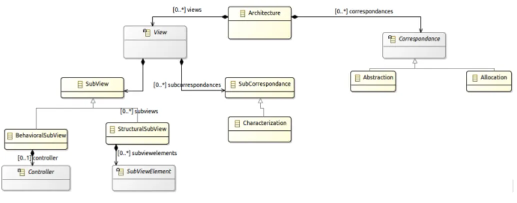
specify-Figure 2: Multi-View Meta-Model
ing the relationships with the other points of view.
We use MDE [7] to define the syntax of the multi-view system model. MDE is a software design technique which aims to use models at different levels of abstraction for developing systems. A model is built by using and conforming to Domain Specific Modeling Languages (DSMLs). In our work, we use the Modeling Framework (EMF) [13] features to specify our MDE infrastructure. We have Ecore representations for our meta-models and we use Sirius [14] syntax create our models.
We inspired by the concepts defined in IEEE-42010 to describe the architec-ture description. Figure 2 depicts a part of the multi-view approach meta-model (we hide Controller and SubViewElement containments). The root element is
Architecture. An Architecture is a set of views and correspondences.
A View defines the needed elements to describe a specific domain. Each view is split in two Subviews: a StructuralSubView and a BehavioralSubView. The first SubView is composed of subViewElements. It describes, with a component-based approach, the variables and configurations whose value will represent the current state of operation of the controller, seen from other views (e.g. the task graph application, the IP Block ..). The second SubView controls and schedules the execution of the subViewElements and can also controls other views. Further that subviews, each view has SubCorrespondance called Characterization. The latter is the association between a property defined in a subViewElement and its behavior in the controller.
A Correspondence states the relationships between views. We have deter-mined two main types of Correspondences in our architecture description:
Al-location and Abstraction. The first correspondence is commonly employed to
associate an action from an application to a hardware component in the embed-ded platform. The second correspondence specifies that the structural element defined in a view is used in another view to specify features that belong to this particular view.
In the context of power and thermal aware modeling, the system is special-ized in five views, depicted in Figure 1:
• The Backbone View defines the main view of IP block diagrams and in-terconnects.
• T he Application View is an abstract description of use case scenarios describing how typically the architectural computing resources can be ac-tivated.
• The Performance View presents a model to bind duration, latency, through-put for the execution of application tasks onto architecture resource, pos-sibly under power constraints.
• The Power View describes how energy is consumed by application tasks mapped onto architecture resource, at a given performance rate.
• The Thermal View describes how application task executions will heat up the chip depending on their architecture placement, the power consumed and the (performance) duration
4
Views Definition
Figure 1 depicts the Multi-View Overview. We illustrate two interdependent global views: The Backbone View and The Application View. The Backbone View presents a reference to the Power , Performance and Thermal Views. Both Backbone and Application views share a controller which specifies the scheduling and the spacial allocation used to define how application functions are partitioned and executed among architectural components. We detailed below each view separately.
4.1
Backbone View
The Backbone view plays the role of the platform execution of the system. It defines the main view of the IP block diagrams and interconnects. This view presents the reference of objects on which other views shall be “hooked" for their structural definitions. So, in this view, the non-functional properties are not defined, they are specified in dedicated views. For instance, considering a power domain example, the power view definition depends on the elements included in the backbone view, i.e., power experts abstract elements from another view to build their own view. The abstraction action is identified as a Correspondence between views.
The Backbone View owns a StructuralSubView which defines the concepts and relationships needed to describe the hardware architecture. A
SubViewEle-ment is specialized by HwComponent, which represents any hardware
compo-nent (e.g CPU, Bus, Memory, ...) defined in the platform execution. These components are controlled by the controller shared between the Application and the Backbone views. For instance, if a task, which is described in an ap-plication view, is mapped to a CPU, the controller must be notified when the task is executed. Once the controller receives the notification, it sends a control event to the CPU to change its internal mode, e.g., to Busy state.
4.2
Application View
The structural application view represents an abstract task graph, later can-didate to be mapped onto the architecture. The view also should provide the
potential representation (which task and which connexion could be mapped on which block for computation or communication. Optionally, the task could also enforce a clock speed on a processor backbone component for execution, and a power configuration as well, requesting the hardware resource it needs for proper execution.
4.3
Performance View
The performance view is primarily based on the structural definition of clock
domains. Each clock domain encompass a number of blocks from the backbone
architecture view of which they form a partition. In addition, the performance view shall define a (discrete) number of admissible clock speed for every such clock domain. Next to the structural subview (which again remains largely constant a part of the platform definition), the behavioral performance subview shall represent an abstract Clock Management Unit CMU, whose purpose is to select and switch between the clock speed values (by DVFS [15]) according to various inputs from various views.
4.4
Power View
The Power view specifies the elements that intend to supply power and to control power features of system components defined in the Backbone view. To model the structure of the power view, we inspired by the concepts defined in the IEEE-1801 [16] and CPF [17] languages. The power structural subview defines a (discrete) number of power domains, each encompassing some IP Blocks from the backbone architecture views. Each such block must be assigned a power domains, and they may be hierarchical. Power domains can also switch in between a (discrete) number of admissible power states (off, idle, standby, active,..). Moreover, the view defines the admissible vectors connecting these values across different power domains (for instance a mother domain cannot be off while a sister domain remains active). The behavioral power subview, here again, will describe how to select and switch between these allowable power domains, according to inputs from other views (forming a number of connected power state machines).
4.5
Thermal View
The Thermal View describes the domain specified by thermal experts to repre-sent thermal features of the Backbone View elements. Precisely, the structural thermal subview describes an abstract floorplan representations with topology rectangles mapped onto IP blocks from the backbone architecture views. A given block may encompass several rectangles. In addition, the structural ther-mal view should provide the neighboured relation between rectangles, and the laws of temperature diffusion across them (which is continuous, not discrete)
4.6
Inter-View interactions
Of course, as we already mentioned several times, the different view models far from independent, being distinct facets of the same system. Here are the main
inter-view interactions that we could identify, with the ability to impact the global behavior dynamics, and thus the co-simulation process:
• power and temperature may be linked in that chip processor energy con-sumption grows with the rising heat. For instance, the temperature behav-ior in the Thermal View owns a state that is characterized by the thermal equation: dTdt = CP
th + 1
RthCth (T-Tenv), where T is the cpu temperature
(the cpu is an abstracted element from the Backbone View) , Cthand Rth
are respectively the thermal capacitance and resistance of cpu, Tenv is
the cpu environmental temperature and P is the cpu power consumption defined in the power view.
• power and performance may also be linked, which is the exact purpose of DVFS [15] technique that may scale down voltage (and speed) to save energy.
These two relation may be seen as introducing a record of physical law phenomena into the cyberland description of embedded SoC, even through the power-performance relation can largely be described at the discrete level of nominal speed/power ratio.
• The third interview interaction is certainly by far the more complex, as it consists in computing the exact (run-time or compile-time) mapping between application tasks and backbone architecture resources, under the current configuration in terms of processing resource availability, remain-ing battery-level energy availability, and current heat at specific chip dye spots. This can be made arbitrarily complex algorithmically, as some effect of a thermal-power aware Operating System. Here certainly more or less sophisticated SystemC operational models could be devised. In our case, and for our current goal aiming more at the preliminary definition of an in-tegrated multi-view co-modeling framework than a realistic co-simulation environment, we shall assume that task mapping is user-provided (as a static, off-line assignment function to backbone architecture resources.
5
Multi View Analysis
5.1
Synopsys Platform Architect MCO
In our work, we target a hard simulation tool, the Synopsys Platform Architect MCO [18]. The goal of MCO is to provide analysis for the expected system per-formance of a target application. The MCO methodology require two different models combined according to the Y-chart [19] approach:
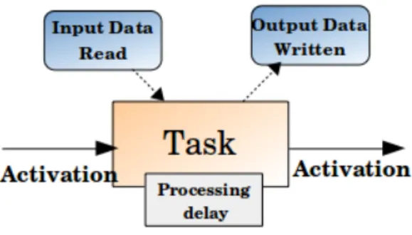
• An application task graph of the target application. The Figure 3 depicts the task graph concept. A task graph is a set of executable tasks (actions) synchronized by transmitting tokens or samples. Hence, each task has its dependencies that specifies in which order the tasks have to be activated for processing a specific set of data. Moreover, each node has a process-ing delay which specifies the amount of time a task occupies a processprocess-ing resource when being activated. The tasks may run in parallel, because they are operating on different sets of data at a time. In the final exe-cution platform, separate tasks may be executed by different processing
Figure 3: The Task Concept
elements. In MCO Platform, the task graph is specified by a number of tables contained in an input CSV (Comma Separated Values) file. There are four basic types of input tables for task graph creation which can be identified by availability of key header names in the leftmost two columns: 1. Taskgraph node table: Each data line of this table specifies the
prop-erties of a task graph node (name, start_delay, wait_delay,..) 2. Taskgraph connection table: Each data line of this table specifies the
properties of a task graph edge.
3. Taskgraph function table: According to the GTL approach, a task node may have a number of functions plugged (processing or mem-ories access). The data rows of this table specify the properties of such functions.
4. Functional Memory table: Task functions or channel implementa-tions may refer to functional memories. Each data line of this table specifies the properties of such a memory for both, mapped and un-mapped tasks.
• A hardware platform model with generic Virtual Processing Unit (VPU) blocks. A VPU is a processing resource for a number of tasks. Once a task graph of an application is created, it can be statically mapped onto the VPU hardware platform. Each VPU in the system will be assigned one or more tasks from the task graph. The VPUs will execute these tasks. When a task executes on a VPU, it will do the required memory accesses on the boundary ports of the VPU block. During simulation, we can collect the performance analysis to focus on the load of the application on the processing elements. It helps answering questions like; how many processing elements of which kind are required, and, what is the best way to partition the target application. The mapping is defined statically in a CSV file. Each data line in this mapping file associates a node to a VPU. We propose to use our multi-view approach to specify the concerning system domains and to generate specialized models needed by the MCO tool in order to analyse the performance of our architecture.
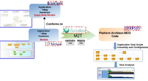
Figure 4: Generation Process
5.2
Transformation Overview
In this paper, we propose to focus only on the generation of the Backbone and Application View models to the MCO tool. To do so, we use the Model Transformation (MT) [20] key aspect of the MDE development process which is a compilation process that allows moving from an abstract model to a more detailed target model.
Figure 4 depicts the transformation overview. Based on our Application and Backbone meta-models specified with Ecore Tools [21], we define models conform to these meta-models using the concrete syntax Sirius [14]. Then, we write a set of transformation rules in an Acceleo [22] template file. Using Acceleo model-driven code generator, an execution chain created using the Application and Backbone meta-models, the defined model and the template file as inputs, can be launched to generate the Architecture and the coresponding Mapping CSV files. Once these CSV files are imported in MCO Platform Architect and the task graph has been validated, we can analyze how the application behaves on the target platform, created in the meta-modeling stage. We can experiment with different mappings and can analyze the impact of the traffic on the Interconnect and Memory systems.
5.3
Case Study
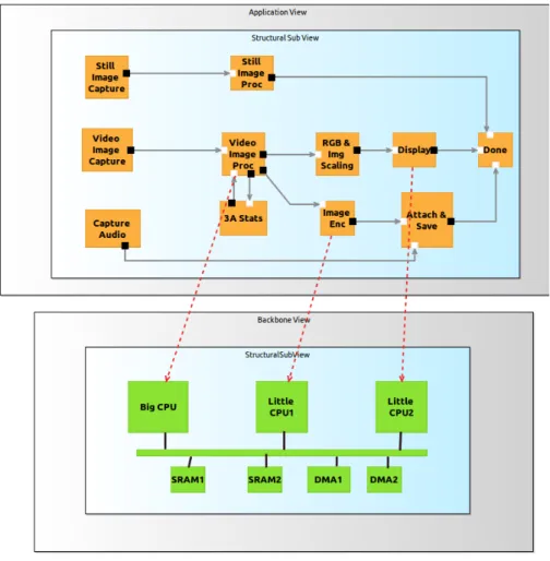
The Figure 5 depicts a model example of a video and still capture task graph which is conform to the Application and Backbone Views meta-models described in 3.2. To do so, we defined a graphical concrete syntax with Sirius based on our multi view approach modeling and which assures the creation of the instance models. In the Backbone View, we propose an example SoC [23] which illustrates abstractly the BIG.Little paradigm, with two little CPUs, a Big CPU, SDRAMs and DMAs connected by a bus. The purpose here is to have as simple as possible a description involving blocks with similar functions (computing cores), but various features concerning performance, power, and to allow temperature
Figure 5: Mapped Task Graph Example
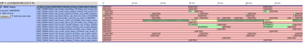
differences and alternative mapping. The red dashed arrow, in the Figure 5 specifies the allocation of an Action to a specific CPU. Using this example and the defined Acceleo rules, we generate two CSV files dedicated to our application and our mapping. These two files are ready to be imported into the MCO Platform Architect. Once they are loaded in the tool and validated, we can focus on the analysis. We show in the figure 6 the analysis of our mapping. The MCO Trace chart shows the states of tasks over time: CREATE, WAITING, READY, RUNNING, and so on. In the Figure 7, we depict the CPUs utilisation through execution. We show that the ’Big’ CPU core (CPU0 in this figure)is the most used when demand is high.
6
Conclusion
The modeling of SoC involves different interdependent expertise domains to deal with functional properties as well as non functional ones while maintaining the system’s consistency. To avoid such issues, we proposed, in this paper, a multi
Figure 6: Mapped Task Graph Analysis Result
Figure 7: CPUs Utilisation
view modeling framework where each specific domain is specified in separate view. We define dependencies among view through links and correspondences, to ensure the coherence of the different views in the system. Furthermore, we shown as a case study how to connect our multi view approach with a real co-simulation tool, Synopsys Platform Architect MCO.
7
Acknowledgement
This work is partially supported by the ANR INS Projects HOPE (ANR-12-INSE- 0003).
References
[1] “Systems and software engineering – architecture description,”
ISO/IEC/IEEE 42010:2011(E) (Revision of ISO/IEC 42010:2007 and IEEE Std 1471-2000), pp. 1 –46, 2011.
[2] A. Girault, B. Lee, and E. Lee, “Hierarchical finite state machines with mul-tiple concurrency models,” in Computer-Aided Design of Integrated Circuits
and Systems, vol. 18, 1999, pp. 742 – 760.
[3] P. R. Panda, “Systemc: A modeling platform supporting multiple design abstractions,” in Proceedings of the 14th International Symposium on
Systems Synthesis, ser. ISSS ’01. New York, NY, USA: ACM, 2001, pp. 75–80. [Online]. Available: http://doi.acm.org/10.1145/500001.500018 [4] A. Vachoux, C. Grimm, and K. Einwich, “Systemc-ams requirements,
de-sign objectives and rationale,” in Proceedings of the Conference on Dede-sign,
Automation and Test in Europe - Volume 1, ser. DATE ’03, 2003, pp.
10 388–.
[5] FMI, “Functional mock-up interface,” https://www.fmi-standard.org/. [6] S. Revol, S. Taha, F. Terrier, A. Clouard, S. Gérard, A. Radermacher, and
key standards: UML and IP-XACT,” in Distributed Embedded Systems:
Design, Middleware and Resources, IFIP 20th World Computer Congress, TC10 Working Conference on Distributed and Parallel Embedded Systems (DIPES 2008), September 7-10, 2008, Milano, Italy, 2008, pp. 69–78.
[7] S. Kent, “Model driven engineering,” in Proceedings of the Third
International Conference on Integrated Formal Methods, ser. IFM ’02.
London, UK, UK: Springer-Verlag, 2002, pp. 286–298. [Online]. Available: http://dl.acm.org/citation.cfm?id=647983.743552
[8] “Proceedings of the workshop on domain-specific modeling languages, berlin, germany, march 14, 2008,” ser. CEUR Workshop Proceedings, D. Fahland, D. A. Sadilek, M. Scheidgen, and S. Weißleder, Eds., vol. 324. CEUR-WS.org, 2008.
[9] A. Khecharem, C. Gomez, J. Deantoni, F. Mallet, and R. De Simone, “Execution of Heterogeneous Models for Thermal Analysis with a Multi-view Approach,” Munich, Germany, Oct. 2014. [Online]. Available: https://hal.inria.fr/hal-01060309
[10] Scilab, “Scilab,” https://www.scilab.org/, 2015.
[11] D. Power, “Aceplorer,” http://www.doceapower.com/products-services/ aceplorer.html, 2013.
[12] C. Gomez, J. DeAntoni, and F. Mallet, “Power consumption analysis using multi-view modeling,” in Power and Timing Modeling, Optimization and
Simulation (PATMOS), 2013 23rd International Workshop on, Sept 2013,
pp. 235–238.
[13] EMF, “Eclipse modeling framework,” http://www.eclipse.org/modeling/ emf/.
[14] Eclipse, “Sirius,” http://eclipse.org/sirius/.
[15] “Circuits and systems magazine, ieee,” Enabling power-efficient DVFS
op-erations on silicon., pp. 10(1):14 –30, 2010.
[16] Accelera, “Unified power format 1.0,” http://www.accellera.org/activities/ p1801.
[17] “Silicon integration initiative,” IEEE Std 1801-2009, pp. C1 –218, 2009. [18] Synopsys, “Platform architect,” http://www.synopsys.com/
platformarchitect/.
[19] B. Kienhuis, E. F. Deprettere, P. v. d. Wolf, and K. A. Vissers, “A methodology to design programmable embedded systems - the y-chart approach,” in Embedded Processor Design Challenges: Systems,
Architectures, Modeling, and Simulation - SAMOS. London, UK, UK: Springer-Verlag, 2002, pp. 18–37. [Online]. Available: http: //dl.acm.org/citation.cfm?id=646466.691571
[20] S. Sendall and W. Kozaczynski, “Model Transformation the Heart and Soul of Model-Driven Software Development,” Tech. Rep., 2003.
[21] Eclipse, “Ecore tools,” http://www.acceleo.org/pages/home/en/. [22] Acceleo, “Mda generator home,” http://eclipse.org/ecoretools/.
[23] P. Greenhalgh, “Big.little processing with arm cortex-a15 and cortex-a,” http://www.arm.com/files/downloads/, 2011.