HAL Id: hal-00299204
https://hal.archives-ouvertes.fr/hal-00299204
Submitted on 6 Jun 2005
HAL is a multi-disciplinary open access
archive for the deposit and dissemination of
sci-entific research documents, whether they are
pub-lished or not. The documents may come from
teaching and research institutions in France or
abroad, or from public or private research centers.
L’archive ouverte pluridisciplinaire HAL, est
destinée au dépôt et à la diffusion de documents
scientifiques de niveau recherche, publiés ou non,
émanant des établissements d’enseignement et de
recherche français ou étrangers, des laboratoires
publics ou privés.
History and present state of the Slano Blato landslide
J. Logar, K. Fifer Bizjak, M. Ko?evar, M. Miko?, M. Ribi?i?, B. Majes
To cite this version:
J. Logar, K. Fifer Bizjak, M. Ko?evar, M. Miko?, M. Ribi?i?, et al.. History and present state of the
Slano Blato landslide. Natural Hazards and Earth System Science, Copernicus Publications on behalf
of the European Geosciences Union, 2005, 5 (3), pp.447-457. �hal-00299204�
Natural Hazards and Earth System Sciences, 5, 447–457, 2005 SRef-ID: 1684-9981/nhess/2005-5-447
European Geosciences Union
© 2005 Author(s). This work is licensed under a Creative Commons License.
Natural Hazards
and Earth
System Sciences
History and present state of the Slano Blato landslide
J. Logar1, K. Fifer Bizjak2, M. Koˇcevar3, M. Mikoˇs1, M. Ribiˇciˇc4, and B. Majes11University of Ljubljana, Faculty of Civil and Geodetic Engineering, Ljubljana, Slovenia 2Civil Engineering Institute, Ljubljana, Slovenia
3Geoinˇzeniring, Ljubljana, Slovenia
4University of Ljubljana, Faculty of Natural Sciences and Technology, Ljubljana, Slovenia
Received: 19 October 2004 – Revised: 13 May 2005 – Accepted: 18 May 2005 – Published: 6 June 2005
Abstract. The Slano Blato landslide is more than 1290 m long, 60 to 200 m wide and 3 to 11 m deep with a volume of about 700 000 m3. It is located in the Eocene flysch region of western Slovenia with a limestone overthrust in the direct vicinity, above the landslide. The landslide moves mainly as a viscous earth flow with occurrences of rapid mud flows. In dry periods or in freezing conditions it behaves as a group of several slow to moderate landslides. The landslide fol-lows the course of the Grajˇsˇcek stream and is presently only 220 m away from Lokavec village. The landslide was first mentioned about 200 years ago. In 1887 it flowed as a liquid flow and reached and destroyed the main road in the valley 2 km away. The Austro-Hungarian monarchy sent one en-gineer to the site and 17 years later the slide was remediated with a series of torrential check dams. The monarchy prohib-ited any construction works in the influence area of the land-slide. During the 20th century the region changed from Aus-trian, Italian, Yugoslav, and finally to Slovenian government in 1991. The relevant Austrian measures and decisions were forgotten during the course of the years, and building permits were issued after the World War II to local people who popu-lated the part of the landslide influence area. Simultaneously, regular maintenance of the excellent past engineering works was neglected. In November 2000 a large landslide of mud and debris was triggered again and it still presents a danger to the relatively new residential houses today. At present, the village is protected against mudflows by a small rockfill dam and by the regulation of the stream bed. In rainy periods re-moval of mud is necessary to maintain safe conditions for the village. The paper discusses the geological, hydrogeological, hydrological and geotechnical conditions for the occurrence of the Slano Blato landslide. The primary reasons for the Slano blato landslide are the geological and hydrogeological conditions just beneath the overthrust of a Triassic limestone plateau over the Eocene flysch of Vipava valley. The direct reason for triggering the earth flow in 2000 was the
inten-Correspondence to: J. Logar
sive precipitation. During the course of years the precipi-tation threshold for earth flow movements has diminished. The landslide has to be remediated for two main reasons – (1) the village below the landslide is endangered, and (2) the landslide is still advancing retrogressively and laterally. The foreseen permanent remediation measures that are currently under construction are briefly presented.
1 Introduction
Even though Slovenia is a small country that occupies 20 252 km2, more than 2500 active landslides are registered and more than 1500 have been put into a GIS database (Ribiˇciˇc, 1999). The majority of them are smaller earth slides and earth slips to the order of 1000 to 10 000 m3. In the last decade of the 20th century, four large landslides occurred with a total mass of the order of 1 000 000 m3 or more (Fig. 1). The oldest one among these landslides is the Macesnik landslide triggered within a fossil landslide mass in 1990 (Majes et al., 20051). The Stoˇze landslide occurred in November 2000 in morainic material overlaying calcare-ous formations (Mikoˇs et al., 2004). The Strug landslide oc-curred in December 2001 on the contact between scaglia and flysch as a complex landslide with a combination of differ-ent slope instability phenomena (Mikoˇs et al., 20052). The fourth large landslide is the Slano Blato landslide that oc-curred in November 2000 in an area geologically character-ized by the overthrust of Triassic limestone over the Eocene flysch. Landsliding of rocks and soils in flysch formations can be observed elsewhere in Europe as well: an overview of landslides associated with the meteorological events in the
1Majes, B., Robas, A., ˇZigman, F., Petkovˇsek, A., and Mikoˇs,
M.: Macesnik landslide yesterday, today and tomorrow, Nat. Haz-ards Earth Sys. Sci, submitted, 2005.
2Mikoˇs, M., Fazarinc, R., ˇZigman, F., Kuder, S., Petkovˇsek, A.,
and Majes, B.: Stepwise remediation of the Macesnik landslide, Nat. Hazards Earth Sys. Sci, in preparation, 2005.
448 J. Logar et al.: History and present state of the Slano Blato landslide
17
FIGURE CAPTIONS
Figure 1: Map of Slovenia with active large landslides.
Fig. 1. Map of Slovenia with active large landslides.
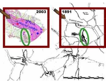
18 Figure 2: A map of Lokavec village and its surroundings from 1891 compared with the map from 2000 (top left). Many houses (marked in red, blue and yellow) were built in the area with high landslide risk (hatched area on the map from 2000) after World War I.
Fig. 2. A map of Lokavec village and its surroundings from 1891
compared with the map from 2003 (top left). Many houses (marked in red, blue and yellow) were built in the area with high landslide risk (hatched area on the map from 2003) after World War I.
European areas with flysch sediments is given by Krejˇc´ı et al. (2002), local situations are given i.e. for Switzerland by Lateltin et al. (1997), for Poland by Margielewski and Urban (2003), for Czech Republic by Krejˇc´ı et al. (2002) and for Greece by Christaras (1997).
2 History of the Slano Blato landslide area
The first landslide on this slope was mentioned about 200 years ago. The original local name Slano Blato in the Slovene language means “salty mud”. An article published in the local newspaper Soˇca, No. 10 from 4 March 1887, reveals that during heavy rain on October 20, 1885, the Grajˇsˇcek stream (Fig. 2) flooded and destroyed the main road, which is 2 km away from Lokavec village, in the length of 30 m and filled the streambed with mud.
The Austro-Hungarian monarchy sent one engineer to the site, who in the early 20th century managed to remediate the
19 (a) (b)
Figure 3: The series of check dams on the tributary of the Grajšček stream before the landslide (A), and the remains of a similar check dam covered by slided material in 2001 (B).
Fig. 3. The series of check dams on the tributary of the Grajˇsˇcek
stream before the landslide (a), and the remains of a similar check dam covered by slided material in 2001 (b).
slide with mostly torrential remediation measures – a series of small check dams (Fig. 3a). These retention dams built on the Grajˇsˇcek stream and its tributaries retained mud and debris and reduced the energy of stream water. On the top of the landslide the engineer found and regulated a water spring. The main remediation works were completed in 1903 and cost 49 857 crowns, which corresponds to 6 250 000 EUR (for the conversion, the comparison of teacher’s salaries were used, as suggested by historians). Figure 3b shows only the top of one of these structures buried by Slano Blato landslide in 2001.
Already more than 100 years ago, prevention was equally important as the execution of the described remediation works on the landslide. Therefore, any construction of new houses in the influence area of the landslide was prohibited by a decree. During the 20th century this area faced a series of political changes and came under the rule of four coun-tries:
– before World War I: Austro-Hungarian monarchy, – after World War I: Italy,
– after World War II: Yugoslavia, – From 1991 onwards: Slovenia.
During the course of years the relevant Austrian measures and decisions were forgotten. After World War I, under the Italian rule, a church was built in the influence area followed by some houses. New building permits were issued after World War II to local people who populated the lower part of the Slano Blato landslide influence area. Towards the end of the 20th century regular maintenance of supporting check dams (Fig. 3a) was largely neglected.
Figure 2 shows a map of the Lokavec area in 1891. A large number of new houses that were built in the area after World War I in the hatched area, which indicates the influence area of the Slano Blato landslide. All old buildings from the 19th century lie outside this area (within the ellipse in Fig. 2).
J. Logar et al.: History and present state of the Slano Blato landslide 449
20 Figure 4: A far and a close view of the Slano Blato landslide.
Fig. 4. A far and a close view of the Slano Blato landslide.
The water spring that was regulated during the remediation works at the beginning of the 20th century in the upper part of the old Slano Blato landslide, was in bad condition a few years before the new initiation of the Slano Blato landslide in 2000. We suggest that, as a consequence of infiltration and deep seepage of spring waters, the clayey gravel soils slowly became fully saturated with water and initiated a landslide af-ter a period of strong precipitation in autumn 2000 (Figs. 16 and 18). The initial sliding was triggered on 19 November 2000, during a heavy rain period. Its initiation was nearly simultaneous with the large Stoˇze debris landslide and debris flow in Log pod Mangartom (Mikoˇs et al., 2004), 60 km to the northwest.
After November 2000, in the upper part of the Slano Blato landslide, wide cracks allowed a large amount of rain ter to penetrate into the ground. Together with ground wa-ter and wawa-ter from the Grajˇsˇcek stream and its tributaries, the rain water triggered a viscous flow of mud and debris. The earth flow (according to the landslide classification of the flow type; Hungr et al., 2001) moved along the Grajˇsˇcek stream towards the Lokavec village with weather-dependent rates, reaching a maximum of 100 m/day. At the end of 2004 the landslide area reached a length of 1290 m and a width be-tween 60 and 200 m. It is located at altitudes bebe-tween 270 m and 640 m above sea level. The landslide affected an area of approximately 15 ha. Having a thickness from 3 to 11 m, the volume of the sliding mass was estimated as 700 000 m3. Figure 4 presents two views on the landslide. The landslide presents a serious hazard for a part of Lokavec village. In or-der to plan effective remediation measures, field geological and geotechnical investigations were performed.
The following five stages of the Slano Blato landslide de-velopment can be distinguished:
1. The landslide was triggered on 19 November 2000, probably at an altitude of 570 m a.s.l. The continuous geological observations of the landslide started on 21 November. Therefore, the location of the initial event was deduced from the situation encountered during the first visit, taking into account the original state. The date of landslide occurrence was determined according to the witness, who noticed the mud in the Grajˇsˇcek stream on
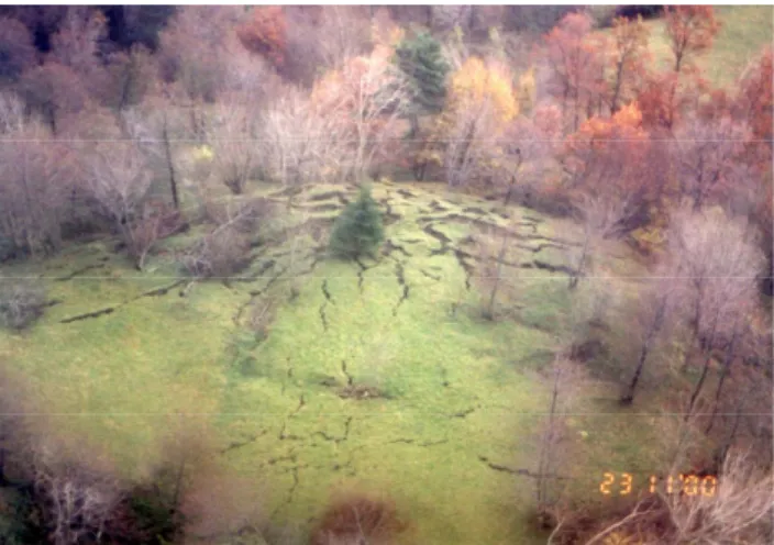
21 Figure 5: The photo taken on November 23, 2000, at the location later on referred to as the “Lake of Mud” just before the vegetation was ripped off. Note the pronounced heave in the centre due to the pressure caused by the soil sliding.
Fig. 5. The photo taken on 23 November 2000, at the location later
on referred to as the “Lake of Mud” just before the vegetation was ripped off. Note the pronounced heave in the centre due to the pres-sure caused by the soil sliding.
19 November. Due to continuous rainfall in that period, the sliding mass soon became liquid and found its way downwards along a narrow channel. A few days later, a large retrogressive rotational slide occurred above the initial scarp. This retrogressive sliding continued slowly until the present day resulting in the formation of sev-eral cracks above the main scarp, which is presently at the altitude of 640 m a.s.l. The liquid mud and de-bris flowed from this landslide area towards the village of Lokavec, causing high pressure on the slope below (Fig. 5), and it took a few days before the viscous earth flow removed the grass and trees. The deformation pat-tern with pronounced heave in the centre of Fig. 5 shows the enormous pressure increase in the soil layers below the surface. The mudflow stopped temporarily 400 m downward at the altitude of 460 m a.s.l. in the area re-ferred to as the “Lake of Mud”. This first phase lasted 5 days until 23 November 2000.
2. During the second phase, a large amount of mud and debris accumulated in the ”Lake of Mud”. The rate of advancement of the head of the earth flow dropped from the initial 60 to 100 m/day to only a few meters a day. The head of the earth flow reached a sandstone outcrop and split in two parts. On 18 December 2000, the front stopped at the altitude of 380 m a.s.l., further 300 m downwards of the outcrop. The photographs in Figs. 6a and 6b show the same area when the “Lake of Mud” formed and after the earth flow found its way fur-ther downstream.
3. Increased rainfall amount in March 2001, along with accumulation of a critical mass in the “Lake of mud”, caused a new advancement of the earth flow on 20 March 2001. The head of the earth flow moved again at a rate of more than 10 m/day and traveled a distance of 330 m until it stopped on 25 April 2001. On its way
450 J. Logar et al.: History and present state of the Slano Blato landslide
22 (a) (b)
Figure 6: The “Lake of Mud” before (A) and after (B) the mud broke the barrier and flowed further downstream.
Fig. 6. The “Lake of Mud” before (a) and after (b) the mud broke
the barrier and flowed further downstream.
23 Figure 7: Several minor mudflows occurred in October 2001.
Fig. 7. Several minor mudflows occurred in October 2001.
the earth flow covered the 16 m high waterfall of the Grajˇsˇcek stream. From the top of the landslide most of the material flowed downwards and a 50-m-long and 50-m-wide lake of water formed in a depression that re-mained. While the front of the earth flow stayed at the same position for some months, movement of wet soil masses continued on the surface along the entire length of the earth flow. Each time that sufficient material was accumulated in the “Lake of Mud”, intensive flowing was observed in the lower part of the earth flow.
4. In October 2001 several minor, very rapid to extremely rapid mudflows (according to Cruden and Varnes, 1996) generated from the lower part of the earth flow and fol-lowed the Grajˇsˇcek stream bed through the village of Lokavec (Fig. 7). The mudflows were different in vol-ume, density, and in the rate of advance.
5. At the beginning of 2002 a small rockfill dam with a bottom outlet was constructed in the Grajˇsˇcek stream bed some 280 m from the village of Lokavec to protect it against the potential mudflows. Up to 5000 m3of de-bris could be retained behind the dam (Fig. 8). During the autumn and winter 2001—2002, up to 200 000 m3 of mud and debris were mechanically removed from the area of the front of the earth flow and deposited on a dumping site in the valley bottom outside the village of Lokavec. The aim of this remediation measure was to protect the rockfill dam and the village of Lokavec
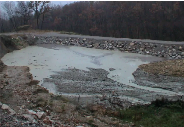
24 Figure 8: The rockfill dam that can retain up to 5,000 m3 of mud and debris was
constructed to protect the village of Lokavec from extremely rapid mud flows generated at the surface of the stopped earth flow masses.
Fig. 8. The rockfill dam that can retain up to 5000 m3of mud and debris was constructed to protect the village of Lokavec from ex-tremely rapid mud flows generated at the surface of the stopped earth flow masses.
25 Figure 9: Engineering geological map of the Slano Blato landslide area.
Fig. 9. Engineering geological map of the Slano Blato landslide
area.
in case of a sudden new fast advancement of the earth flow. The situation in the lower part of the earth flow stabilized after spring 2002, partially due to the fact that 2003 was rather dry (Figs. 17 and 20). Due to some technical measures, which are discussed later, the situa-tion improved also along the rest of the landslide.
3 Geological conditions
The Slano Blato landslide is located exactly at the border of Triassic limestone and Eocene flysch, as shown in the engi-neering geological map (Fig. 9). The whole area consists of larger synclines and anticlines. The Eocene flysch consists of layers of marl and sandstone few centimeters up to few meters thick.
Limestone was overthrusted on the flysch over a very large distance. It is known as a Trnovski overthrust. The conse-quence of big tectonic movements in the past was a highly tectonized rock in that region. The flysch rock is strongly folded and ruptured.
The contact between limestone and flysch has the Dinaric orientation with a dip of 10◦ in NE direction. Based on the sediment texture, the inverse position of layers was
es-J. Logar et al.: History and present state of the Slano Blato landslide 451
26 Figure 10: Geological longitudinal section along the Slano Blato landslide area. The symbols have the same meaning as in the legend to Fig. 9.
Fig. 10. Geological longitudinal section along the Slano Blato landslide area. The symbols have the same meaning as in the legend to Fig. 9.
27
Figure 11: The longitudinal seismic refraction section along the landslide.
Fig. 11. The longitudinal seismic refraction section along the landslide.
tablished in the upper part of the landslide. Several faults with Dinaric orientation (330–345/55–75◦) were observed throughout the whole landslide area.
Flysch, in the region of the landslide, is divided into three regions:
– layers of predominant sandstone in the thickness of at least one or several meters
– region with alternation of marl and 10 cm thick layers of sandstone
– region with predominant layers of marl.
The water inflow was observed in fissured layers of sand-stone at several depths, during the borehole drilling, almost as a rule. The dip direction of layers is NE, which is, from the point of view of global stability, favourable with respect to the direction of the slope. The main part of the landslide finishes at the outcrop of a several meters thick layer of sand-stone forming a 16-m-high waterfall before the earth flow.
The flysch rock is covered by heterogeneous clayey gravel with blocks of Triassic limestone, sandstone and marl. The thickness of this gravely layer is 3 to 11 m, and was deter-mined by borehole logging (Fig. 10) and geophysical inves-tigations, in particular the seismic refraction method (Car, Stopar, 2003) with one longitudinal section (Fig. 11) and sev-eral cross sections was applied.
The in situ investigations were performed in several steps from 2001 to 2003. Altogether 21 boreholes were made. Samples taken from these boreholes were investigated in the laboratories to obtain relevant material properties.
4 Material properties
4.1 Flysch bedrock
The strength characteristics of flysch bedrock were deter-mined empirically according to the Hoek and Brown failure criterion (Marinos and Hoek, 2000, 2001) using the basic pa-rameters GSI, UCS and mi value of 7 as suggested by Hoek
as an average value for marl. The Geological Strength In-dex (GSI) (Hoek, 1994; Hoek et al., 1995; Hoek and Brown, 1997; Hoek et al., 1998) for the marl flysch layers was be-tween 15 and 25 for different locations. The uniaxial com-pressive strength (UCS) of flysch marl was very low, between 155 and 323 kPa, which classified these layers from the land-slide area into the group of soft rocks. Based on these data, the angles of internal friction ϕ and cohesion intercept c were determined (ϕ between 22◦ and 26◦and c between 80 and 110 kPa). Similar values were measured by direct shear tests on five marl samples: angle of internal friction between 22◦ and 27◦with cohesion intercept between 0 and 52 kPa.
Mea-452 J. Logar et al.: History and present state of the Slano Blato landslide
Table 1. Main material properties of the Slano Blato landslide
ma-terial. Property 2001 2002 2003 Number of samples 12 41 18 Unit weight γ (kN/m3) 18.5–20.7 20.6–22.1 19.0–21.8 Liquid limit LL (%) 40–52 45–51 37–53 Plastic limit PL (%) 19–24 20–23 21–24 Plasticity Index PI (%) 20–32 25–28 16–31 Natural water content w0(%)
- natural material 20–41 20–24 12–27
- grains <2 mm 27–30
Angle of internal friction ϕ (◦) 17–30 24–27 21–24
Cohesion (kPa) 5–22 0–5 18–20
1Four large samples were taken from trial pits (together several 100
kg of soil mass).
28 Figure 12: Grain size distribution for selected samples from the landslide material . Fig. 12. Grain size distribution for selected samples from the
land-slide material.
sured water content on samples of marl varied between 8.6 and 13.7%.
On four samples from rare sandstone layers only the UCS was determined in laboratory, and values from 11 do 40 MPa were obtained. Through the established GSI=45, high strength characteristics were empirically estimated (Hoek, Marinos, 2000): ϕ0=46◦and c0=0.8 MPa.
4.2 Landslide material
The samples of the landslide material were taken from bore-holes and from the trial pits near the surface in each of the investigation stages. 12 soil samples from boreholes were tested in 2001, in 2002 four samples of mud flow mate-rial were taken from tmate-rial pits and in 2003 29 samples from boreholes were tested in laboratory. The basic tests (water content, grain size distribution, liquid and plastic limit, unit weight) were performed and supplemented by triaxial and di-rect shear strength tests. The summary of test results is given in Table 1. Additionally the fractions of soil samples passing the 0.063 mm sieve were tested in viscometer to determine the viscosity and limit shear stress under flow conditions.
29 Figure 13: Water contents of samples of mudflow material in three investigation campaigns with regard to the fines content.
Fig. 13. Water contents of samples of mudflow material in three
investigation campaigns with regard to the fines content.
The grain size distribution was analyzed for 20 samples. The results for 5 selected samples are presented in Fig. 12 (2 samples were tested in 2002 and 3 in 2003). The presented grain size distribution curves represent the whole range of measured grain size distributions. The majority of samples can be classified as silty clays with up to 45% gravel and sand particles. In other samples gravel and sand particles dominate (60%) over the silt and clay (40%). Such samples are found in the upper part of the landslide and at the loca-tions where fracloca-tions of fines were partly washed away.
Figure 13 presents measured water contents as a function of the percent of fines in samples from the mudflow material. It can be seen that the water content decreases from 2001 to 2003. It appears that the landslide materials were drying out, however, it has to be emphasized that most of the field inves-tigations in 2003 were performed in a relatively dry period.
Other characteristics of the landslide material are given in Table 1. Atterberg limits were determined on soil grains passing the 0.08 mm sieve. Shear strength characteristics were obtained on reconstituted specimens from the soil grains passing the 2 mm sieve by standard undrained con-solidated triaxial tests (in 2002) and in direct shear tests (in 2001 and in 2003).
A test in a large oedometer cell (250*120 mm=D*H) was performed on a liquid landslide mass with initial water con-tent of 31%, at which the fine matrix was in liquid state. Only one such test was performed on the samples with maximum grain size of 20 mm with the aim of investigating the influ-ence of the consolidation on the reduction of water content. By loading the specimen up to 320 kPa, the water content was reduced to 19%. Figure 14 shows the result as a graph of water content vs. depth, assuming the unit weight of de-posited sliding mass γ =21 kN/m3. This result proved that the deposition of the sliding mass at locations where it can con-solidate and partly dry up will cause an important increase in shear strength. At the same time, lower water contents obtained on site in 2003 mean that the material dries up
eas-J. Logar et al.: History and present state of the Slano Blato landslide 453
30 Figure 14: Oedometer curve (void ratio e vs. vertical pressure σ’) plotted as depth (z) vs.
water content assuming that z = σ’/γ and w = e γw / γs.
Fig. 14. Oedometer curve (void ratio e vs. vertical pressure σ0) plotted as depth (z) vs. water content assuming that z=σ0/γ and
w=eγw/γs.
ily. Evidence from the field showed that after relatively short dry periods an up to 1.0-m-thick crust formed, which addi-tionally contributed to the stabilisation of deposited landslide mass.
The viscosity (Fig. 15) and limit shear stress (Fig. 16) were measured in viscometer on fines with grain size <63 µm. It was established that the limit shear stress dropped rapidly with increasing water content, from 100 kPa at 40% water content to only a few hundred Pa at 60% water content. The coefficient of viscosity decreased from 108to 105Pa.s for the same increase in water content.
5 Hydrogeological investigations
The coefficients of permeability were determined by 8 slug tests and 1 pump test. The saturated conductivity, k, varied in the following intervals:
1. 10−7–10−8 m/s, for the marl and massive sandstone (flysch layers) and dense gravely clay as a part of the landslide material
2. 10−6–10−5 m/s for tectonized marl and fissured sand-stone, and
3. 10−4–10−3 m/s for clayey gravel with pieces of
lime-stone and siltlime-stone as a part of the landslide mass.
The most important underground flow was found in the gravely layers. The water, which supplies the landslide, in-filtrates into the ground in the catchment in the landslide’s hinterland. Then water slowly seepaged into the landslide area through the layers of clayey gravel of intermediate and low permeability.
Material with intermediate permeability existed even within the layers of flysch at a depth of more than 20 m, usu-ally in fissured layers of marl and sandstone. Based on this result and on other field observations (locally the surface soil was in a liquid state even after longer dry periods; heave of
31 Figure 15: Viscosity vs. water content as measured in viscometer on four specimens. Fig. 15. Viscosity vs. water content as measured in viscometer on
four specimens.
32 Figure 16: Limit shear stress vs. water content measured in viscometer on four specimens.
Fig. 16. Limit shear stress vs. water content measured in viscometer
on four specimens.
the ground shown in Fig. 5, indicating that the ground be-came soft due to the water emerging from the bedrock and not from the surface) it was suggested that an important in-flux of water to the sliding mass came also from the lower flysch layers. Later on this was confirmed when the first two large hollow concrete shafts with a diameter of 5 m were made as a part of remediation actions. Up to 15 m3of water per day can be collected in one shaft.
Based on the measurements of springs, it was calculated that on the rainy days a water influx of 260 to 2600 l/day on the 100 m2area is possible from fissured layers of sandstone. Those inflows are not continuous. The position of individual pervious layers allowed for local water accumulation. The most pronounced water accumulation was in the depression area in the upper part of the initial landslide.
454 J. Logar et al.: History and present state of the Slano Blato landslide
Table 2. Results of chemical analysis of 5 water samples.
Sample 1 Sample 2 Sample 3 Sample 4 Sample 5
location spring above
upper channel stream above the Waterfall upper part – center upper part – west upper channel pH 7.15 7.88 7.50 7.68 8.01 electroconductivity (µS/cm) 1550 1695 688 679 1369 NO3(mg/l) 3.2 7.5 9.6 3.4 35.6 SO4(mg/l) 584 753 121 124 569 Cl (mg/l) 71.0 62.1 4.44 1.78 5.33 PO4(mg/l) <1 <1 <1 <1 <1 Ca (mg/l) 108.1 106.6 166.9 107.4 92.4 K (mg/l) 9.39 9.22 2.60 2.48 4.57 Mg (mg/l) 77.1 49.2 111.1 18.5 34.0 Na (mg/l) 149.3 200.1 18.4 21.0 193.9 HCO3(mg/l) 74.8 98.3 41.2 26.9 23.5 33 Figure 17: Cumulative precipitation measured in the rain gauge in the village of Lokavec for four years.
Fig. 17. Cumulative precipitation measured in the rain gauge in the
village of Lokavec for four years.
The discharge measurements of the Grajˇsˇcek stream were done at different locations in the landslide area. The dis-charges depended on the amount of precipitation and ranged from 0.2 l/s up to the 50 l/s or more. During the period of strong precipitation the stream rose in two hours from 1 l/s to 50 l/s. In dry periods the flow of the Grajˇsˇcek stream de-creased very rapidly.
Due to the interesting name Slano Blato (Salty mud) and the indication from the local newspaper Soˇca from 1887, which documented the old saying that “when water from Slano Blato had flooded the grass, the grass withered”, chem-ical analyses were performed on five water samples from different locations within the landslide (see Table 2). It was found out that the water is slightly mineralized with in-creased concentrations of sulphates and sodium (samples 1, 2 and 5). The fact that the increased concentrations of salts were found along the upper channel and above the Water-fall, but not close to the scarp (samples 3 and 4), confirms an important contribution of underground water from a flysch aquifer to the sliding process.
34 Figure 18: 25-day cumulative precipitation vs. daily precipitation with triggering of 8 major sliding and/or earth flow events.
Fig. 18. 25-day cumulative precipitation vs. daily precipitation with
triggering of 8 major sliding and/or earth flow events.
Literature review showed that the salt content slightly in-fluences also the flow properties of fine-grained soil if the salinity is above the flocculation threshold (Perret et al., 1996). Both limit shear stress and viscosity increase due to the increased salinity. So far no such tests have been per-formed for the materials from the Slano blato landslide.
6 Precipitations and landslide movements
Figure 17 shows the cumulative rainfall from October 2000 to July 2004. The data are presented for one-year periods starting from October to September of the next year. Novem-ber 2000 was by far the most rainy month in the observed pe-riod with 591 mm of rainfall. Then follow March 2001 and September 2001 with 335 mm of rainfall, whereas during all other months less than 250 mm of rainfall was measured. The maximum daily precipitation in November 2000 did not ex-ceed 67 mm, but daily values up to 95 mm were observed a few times in the following years. However, daily rainfall amounts did not correlate well with the observed rates of the
J. Logar et al.: History and present state of the Slano Blato landslide 455
35 Figure 19: 25-day cumulative rainfall and measured displacements of two points. (see Figure 22 for the location of the measuring points)
Fig. 19. 25-day cumulative rainfall and measured displacements of
two points. (see Fig. 22 for the location of the measuring points).
36 Figure 20: Cumulative annual rainfall and the periods of intensive mass movements.
Fig. 20. Cumulative annual rainfall and the periods of intensive
mass movements.
advancement of the front of the earth flow. Figure 18 shows the diagram of 25-day cumulative precipitation vs. daily pre-cipitation. Large dark dots mark the eight days when signif-icant earth movements started, grey dots show all days dur-ing intensive movemets, whereas small dots show all other days after 19 November 2000. The eight triggering events are numbered consecutively, showing that an extremely in-tensive precipitation had been necessary to provoke the first sliding. Each of the next triggering events happened after less rainfall.
In 2000, a temporary system of measuring points was set up. Displacements of the earth flow were followed, us-ing GPS technology and with classical geodetic measure-ments. The displacements of some points reached the val-ues of 150 m until they were lost from the measuring system. The majority of the measuring points was destroyed during the works on the drainage system in the part of the landslide. Until that time the largest displacements were observed in the upper part of the landslide, e.g. points OR-3 and P-100 (see Figs. 19 and 22).
Figure 20 presents cumulative annual rainfall (zeroed each 1 October to keep the reasonable scale) and the periods of intensive sliding mainly connected with the progression of the earth flow towards the village of Lokavec.
37 Figure 21: The area of Grajšček stream cross-section under the bridge is important for the flood and mudflow safety and therefore needs constant maintenance. The photo shows the cross-section partly filled with mud, which needs intervention.
Fig. 21. The area of Grajˇscek stream cross-section under the bridge
is important for the flood and mudflow safety and therefore needs constant maintenance. The photo shows the cross-section partly filled with mud, which needs intervention.
38 Figure 22: Plan view of the upper part of the Slano Blato landslide with 5 reinforcing and dewatering shafts-dowels and deep drainage trenches.
Fig. 22. Plan view of the upper part of the Slano Blato landslide
with 5 reinforcing and dewatering shafts-dowels and deep drainage trenches.
In the years 2003 and 2004 some geodetic measurements were done for the upper part of the landslide. Although the period from November 2003 to April 2004 was dry, the top of boreholes moved by 16 m. Measurements indicated ongoing moderate movements of the landslide.
In some boreholes the inclinometer casings were placed to allow the monitoring of horizontal displacements. The mea-surements in the upper part of the landslide indicated that the sliding plane was not limited only to the contact between clayey gravel and flysch, but it could be even deeper. A bore-hole from that region showed the thickness of the gravely layer of 5 m, but the horizontal movements were measured up to the depth of 9.5 m. Another two inclinometer measure-ments, located at the edges of the landslide, ascertained the slip surface on the contact between gravely and flysch layer.
456 J. Logar et al.: History and present state of the Slano Blato landslide
39 Figure 23: Longitudinal section of the Slano Blato landslide with reinforcing and dewatering dowels at the top and deep drainage trenches along the landslide.
Fig. 23. Longitudinal section of the Slano Blato landslide with
rein-forcing and dewatering dowels at the top and deep drainage trenches along the landslide.
7 Risk reduction and remediation measures
Soon after the landslide had been triggered, a geological ob-servation started. The intensive retrogressive enlargement of the landslide behind the original scarp and the earth flow pro-gression from the landslide initiation area towards the village of Lokavec urged for the implementation of risk reduction measures. The landslide mass behaviour in the field and the results of the laboratory investigations showed the possibility of moving at least some nearly liquid landslide material from the central part to the stable sides of the earth flow course. Once there, the mechanically moved material would dry up and get stabilized. Due to the terrain morphology and the presumed potential instability of nearby dumping site loca-tions in the vicinity of the landslide area, this was not the solution for large soil masses. The following measures have been implemented so far to reduce the risk for the village of Lokavec:
– Several drainage trenches in the upper part of the land-slide were put in function in 2002, and were destroyed in 2003 due to retrogressive sliding. They were rebuild in 2004,
– Removal of 200 000 m3of the earth flow masses in the area of its front, for which a remediation of the local road was necessary,
– A small rockfill dam against fast mudflows,
– The Grajˇsˇcek streambed was enlarged, made concave and protected by rip-rap to withstand fast flowing mud-flows (Fig. 21).
Remediation measures planned for the future are the follow-ing (see Figs. 22 through 24):
– A drainage system in the upper part of the landslide. – Construction of a set of 5 reinforced concrete shafts,
which should act simultaneously as a dewatering wells and retaining structure (dowels).
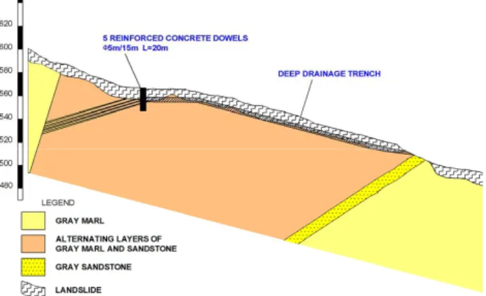
40 Figure 24: Cross section across the future reinforcing and dewatering dowels together with geoseismic refraction profile. (see Figure 22 for the location of the geoseismic profile)
Fig. 24. Cross section across the future reinforcing and dewatering
dowels together with geoseismic refraction profile (see Fig. 22 for the location of the geoseismic profile).
– Deep drainage trenches will be constructed along the earth flow course.
8 Conclusions
From the field and laboratory investigations the following conclusions can be drawn:
1. Even though the Slano Blato landslide was already re-mediated in the past, it was reactivated partially due to the bad condition of spring regulation works carried out at the beginning of the 20th century at the top of the landslide. The omission of maintenance of Grajˇsˇcek and its tributaries stream courses intensified the pro-gression of the earth flow later on. The intensive po-litical changes in the region during the 20th century were therefore partly the reason for the landslide re-occurrence and for the potential damage to the village that spread during last century to the area influenced by the Slano Blato landslide.
2. The primary reason for the landslide on this particular location is the overthrust of a Triassic limestone plateau over the Eocene flysch of Vipava valley. This overthrust caused significant fracturing and consequently weather-ing of the flysch layers. Along the entire overthrust line numerous evidences of old landslides can be observed and have been confirmed by the ground investigations and earthworks for the new motorway.
3. Unfavorable hydrogeological conditions are also con-nected with this general geological feature. The specific position of water-bearing limestone behind and above the flysch formation with lower conductivity assures the constant water inflow to the fractured and weathered fly-sch.
4. The direct reason for the earth flow that was triggered in November 2000 was the increased water inflow due to intensive precipitation.
J. Logar et al.: History and present state of the Slano Blato landslide 457
5. Periods with intensive earth flow movements corre-spond with higher precipitation. During the course of years the precipitation threshold for earth flow move-ments diminishes.
6. Earth and mud flows have occurred at the same location in the past. The main difference is that the landslide in-fluence area was not populated before World War I. The presence of the village in the landslide influence area to-day, calls for the implementation of risk reduction and remediation measures.
7. Dewatering shall be the main remediation measure. Fur-thermore, the soil masses behind the present scarp have to be kept stable in order to minimize the earth flow vol-ume.
Acknowledgements. The authors would like to thank the State Re-habilitation Commission of the Republic of Slovenia for financial support to the project. The assistance of I. Benko who searched the archives is gratefully acknowledged.
Edited by: P. Reichenbach
Reviewed by: P. Frattini and another referee
References
Car, M. and Stopar, R.: Geophysical measurements on the Slano Blato landslide. Internal report (in Slovene), 2003.
Christaras, B.: Landslides in iliolitic and marly formations. Exam-ples from north-western Greece, Engineering Geology, 47, 1–2, 57–69, 1997.
Cruden, D. M. and Varnes, D. J.: Landslide types and processes, in: Landslides Investigation and Mitigation: Transportation Re-search Board, edited by: Turner, A. K. and Schuster, R. L., US National Research Council, Special report 247, Washington, DC, 35–75, 1996.
Hoek, E.: Strength of rock and rock masses, ISRM News Journal, 2, 2, 4–16, 1994.
Hoek, E., Kaiser, P. K., and Bawden, W. F.: Support of underground excavations in hard rock, Rotterdam, Balkema, 1995.
Hoek, E. and Brown, E. T.: Practical estimates of rock mass strength, Intnl. J. Rock Mech. & Mining Sci. & Geomechanics Abstracts, 34, 8, 1165–1186, 1997.
Hoek, E., Marinos, P., and Benissi, M.: Applicability of the Ge-ological Strength Index (GSI) classification for very weak and sheared rock masses. The case of the Athens Schist Formation, Bull. Engg. Geol. Env., 57, 2, 151–160, 1998.
Hungr, O., Evans, S. G., Bovis, M. J., and Hutchinson, J. N.: A Review of the Classification of Landslides of the Flow Type. En-vironmental & Engineering Geoscience, 7, 3, 221–238, 2001. Krejˇc´ı, O., Baro, I., B´ıl, M., Hubatka, F., Jurov´a, Z., and Kirchner,
K.: Slope movements in the Flysch Carpathians of Eastern Czech Republic triggered by extreme rainfalls in 1997: a case study, Phys. Chem. Earth, 27, 36, 1567–1576, 2002.
Margielewski, W. and Urban, J.: Crevice-type caves as initial forms of rock landslide development in the Flysch Carpathians, Geo-morphology 54, 3–4, 325–338, 2003.
Marinos, P. and Hoek, E.: GSI: A geological friendly tool for rock mass strength estimation, Proceedings of the International Con-ference on Geotechnical & Geological Engineering (GeoEng, 2000), Technomic Publishing Co. Inc., Melbourne, Australia, 1422–1440, 2000.
Mikoˇs, M., ˇCetina, M., and Brilly, M.: Hydrologic conditions re-sponsible for triggering the Stoˇze landslide, Slovenia, Engineer-ing Geology 73, 3–4, 193–213, 2004.
Lateltin, O., Beer, C., Raetzo, H., and Caron, C.: Landslides in Fly-sch terrains of Switzerland: Causal factors and climate change, Eclogae Geologicae Helvetiae, 90, 3, 401–406, 1997.
Perret, D., Locat, J., Martignoni, P.: Thixotropic behavior during shear of a fine-grained mud from Eastern Canada, Engineering Geology 43, 31–44, 1996.
Ribiˇciˇc, M.: Kataster plazov = Inventory map of landslides. Pro-ceedings of 2nd Slovenian Conference on Landslides, ˇSmarje pri Jelˇsah, Ministry of Environment and Physical Planning, (in Slovene), 36–54, 1999.
Terlien, M. T. J.: The determination of statistical and deterministic hydrological landslide-triggering thresholds, Int. J. Geosci., Env. Geology, 35/2–98, 1998.
Zupanˇciˇc Valant A.: Viscometer tests on the samples from the Slano Blato landslide, Internal report (in Slovene), 2003.