HAL Id: insu-03218907
https://hal-insu.archives-ouvertes.fr/insu-03218907
Submitted on 6 May 2021
HAL is a multi-disciplinary open access
archive for the deposit and dissemination of
sci-entific research documents, whether they are
pub-lished or not. The documents may come from
teaching and research institutions in France or
abroad, or from public or private research centers.
L’archive ouverte pluridisciplinaire HAL, est
destinée au dépôt et à la diffusion de documents
scientifiques de niveau recherche, publiés ou non,
émanant des établissements d’enseignement et de
recherche français ou étrangers, des laboratoires
publics ou privés.
Distributed under a Creative Commons Attribution - NoDerivatives| 4.0 International
License
minerals during geological carbon storage: Modelling
based on a field CO2 injection experiment
Mike Bickle, Niko Kampman, Hazel Chapman, Chris Ballentine, Benoit
Dubacq, Albert Galy, Tule Sirikitputtisak, Oliver Warr, Max Wigley, Zheng
Zhou
To cite this version:
Mike Bickle, Niko Kampman, Hazel Chapman, Chris Ballentine, Benoit Dubacq, et al..
Rapid
reactions between CO2, brine and silicate minerals during geological carbon storage: Modelling
based on a field CO2 injection experiment. Chemical Geology, Elsevier, 2017, 468, pp.17 - 31.
�10.1016/j.chemgeo.2017.07.031�. �insu-03218907�
Contents lists available atScienceDirect
Chemical Geology
journal homepage:www.elsevier.com/locate/chemgeo
Rapid reactions between CO
2
, brine and silicate minerals during geological
carbon storage: Modelling based on a
field CO
2
injection experiment
Mike Bickle
a,⁎, Niko Kampman
a,b, Hazel Chapman
a, Chris Ballentine
c, Benoit Dubacq
a,d,
Albert Galy
a,e, Tule Sirikitputtisak
f, Oliver Warr
g, Max Wigley
a, Zheng Zhou
haDept. Earth Sciences, Downing Street, Cambridge CB2 3EQ, UK
bShell Global Solutions International, Kessler Park 1, 2288 GS Rijswijk, The Netherlands cDepartment of Earth Sciences, South Parks Road, Oxford OX1 3AN, UK
dSorbonne Universités, UPMC Univ. Paris 06, CNRS, Institut des Sciences de la Terre de Paris (ISTeP), 4 place Jussieu, 75005 Paris, France eCRPG, Centre de Recherches Pétrologiques et Géochimiques, 15 rue Notre Dame des Pauvres, 54501 Vandoeuvre lès Nancy, France fInternational Affairs and Cooperative Education, Prince of Songkla University, Surat Thani Campus, Thailand
gDepartment of Earth Sciences, Earth Sciences Centre, University of Toronto, Toronto, Ontario M5S 3B1, Canada hLancaster Environment Centre, Lancaster University, Lancaster LA1 4YQ, UK
A R T I C L E I N F O
Keywords:
Geological carbon storage CO2injection experiment
Fluid-mineral reactions Plagioclase dissolution rates Enhanced oil recovery
A B S T R A C T
The dissolution of CO2into formation brines and the subsequent reactions of the CO2-charged brines with
reservoir minerals are two key processes likely to increase the security of geological carbon-dioxide storage. These processes will be dependent on the permeability structure and mineral compositions of the reservoirs, but there is limited observational data on their rates. In this paper we report the cation and anion concentrations and Sr, oxygen and carbon isotopic compositions of formation waters from four extraction wells sampled at surface, over ~ 6 months after commencement of CO2injection in afive spot pattern for enhanced oil recovery at the Salt
Creekfield, Wyoming. Sampled fluids, separated from the minor oil component, exhibit near-monotonic in-creases in alkalinity and concentrations of cations but little change in Cl and Br concentrations and oxygen and deuterium isotope ratios. The increases in alkalinity are modelled in terms of reaction with reservoir calcite and silicate minerals as the changes influid chemistry and Sr-isotopic compositions are inconsistent with simple addition of injectedfluids sampled over the course of the experiment. The reservoir mineral chemical and isotopic compositions are characterised by sampling core as well as surface exposures of the Frontier Formation elsewhere in Wyoming. The evolution of thefluid chemistries reflects extensive dissolution of both carbonate and silicate minerals over the course of the six months sampling implying rapid dissolution of CO2in the
for-mation waters and reaction of CO2-bearing brines with formation minerals. Rates of CO2diffusion into the brines
and advection of CO2charged brines in the reservoir are sufficiently slow that, if present, calcite should react to
be close to equilibrium with thefluids. This allows estimation of the CO2partial pressures in the sampledfluids
and comparison with the thermodynamic driving force for the relatively rapid average plagioclase dissolution rates of ~ 10− 12mol·m− 2·s− 1.
1. Introduction
Dissolution of CO2in formation brines and the consequent
fluid-mineral reactions in reservoirs are potentially important processes which lead to the long-term security of geological carbon storage (IPCC, 2005; Benson and Cole, 2008; Bickle, 2009). However the rates and ultimate significance of these processes to storage security are poorly constrained. Dissolution of CO2increases brine densities and storage
security, as the denser brines will not be subject to the buoyancy of the super-critical CO2. However the volume of brine needed is 10 to 15
times that of the CO2. The resulting reactions between the acid CO2
-charged brines and reservoir minerals may either increase or decrease storage security. Carbonate minerals in reservoirs will dissolve rapidly (Xu et al., 2007), which will buffer the fluid pH and may increase re-servoir porosities slightly and permeabilities significantly. The acid CO2-saturated brines may corrode caprocks or fault zones but this may
be offset by the more sluggish reactions between brines and silicate minerals causing pH to rise and carbonate minerals to precipitate (Kampman et al., 2016). The latter may blockfluid escape paths and store a fraction of the CO2in much more secure solid forms.
http://dx.doi.org/10.1016/j.chemgeo.2017.07.031
Received 16 December 2016; Received in revised form 26 July 2017; Accepted 31 July 2017
⁎Corresponding author.
E-mail address:mb72@esc.cam.ac.uk(M. Bickle).
Available online 02 August 2017
0009-2541/ © 2017 The Authors. Published by Elsevier B.V. This is an open access article under the CC BY license (http://creativecommons.org/licenses/BY/4.0/).
The key step in the CO2-brine-mineral reactions is the rate at which
the CO2dissolves in the brine. CO2diffusion in brine is sluggish with
diffusion distances at most ~0.2 m in a year or ~1 m in ~30 years. However two processes in reservoirs may substantially increase the rate of CO2dissolution. In more permeable reservoirs the denser CO2
-satu-rated brine may sink setting up a convective circulation that cycles unsaturated brine against an overlying CO2plume. In favourable
set-tings this may cause a significant fraction of the CO2to be dissolved
within decades (e.g.Neufeld et al., 2010). The second mechanism re-lates to the innate heterogeneity of rocks. The well imaged CO2storage
site at Sleipner demonstrates that the injected CO2flows by multiple
paths and is trapped in multiple layers even in a relatively homo-geneous reservoir (e.g.Boait et al., 2012). This increases the CO2-brine
surface area by at least an order-of-magnitude and probably much more, with a corresponding increase in CO2dissolution rates. Nearly all
the porous sedimentary rocks which will comprise the CO2storage
re-servoirs are bedded on scales of ~ 1/3 m and have corresponding order-of-magnitude variations in their permeabilities. This, combined with the natural tendency of the less viscous CO2tofinger when injected into
more viscous brines (Saffman-Taylor instablity, Saffman and Taylor, 1958), will also cause substantial increases in brine-CO2contact areas
and therefore CO2dissolution rates.
However it is difficult or impossible to predict a priori how fast CO2
will dissolve in formation brines. One set of possible observations that indirectly reflect CO2dissolution rates is on the nature and rates of
fluid-mineral reactions driven by the increases in dissolved CO2 in
formation brines. These necessarily need to be made in pilot-scale CO2
injection experiments to reduce flow paths, time scales and allow adequate sampling offluids. There have been a small number of such experiments (see review byKampman et al., 2014) but determination of fluid-mineral reactions in these has either not been attempted, is re-stricted because sampling bore holes were swamped by the CO2plume
within days, the formations contained unreactive quartz-rich lithologies orfluid composition data remains unpublished.
CO2injection for enhanced oil recovery provides opportunities to
investigate the flow, dissolution and brine-CO2reactions in field
set-tings analogous to likely CO2storage sites (e.g.Hovorka et al., 2011;
Worden and Smith, 2004). The industrial exploitation injects sub-stantial volumes of CO2and the continuous production allows
time-series sampling of producedfluids from a distributed set of wells. Dis-advantages include the presence of oil in thefluids and the oil fields often having been subject to a long history of exploitation involving previous waterflooding. Further, fluids sampled from production wells at surface will have decompressed and exsolved CO2precluding direct
measurement of dissolved CO2at reservoir conditions.
In this paper we calculate the nature and progress offluid-mineral reactions from changes in the sampled fluid chemical and isotopic compositions based on sampling and analysing producedfluids from a CO2injection phase for enhanced oil recovery at a site in the Salt Creek
Field, Wyoming. The CO2was injected into the ~ 20 m thick 2nd Wall
Creek sandstone unit and produced fluids were sampled over a six month period after initiation of the CO2injection. The producedfluids
were sampled atfive producing wells (Fig. 1) distributed around the injection well and comprised predominantly brine with a subsidiary fractions of oil and variable proportions of CO2. All the wells show
marked increases in alkalinity during the six months after injection started in wells 37, 38 and 40. Some of this increase can be explained by dissolution of calcite in the reservoir but modelling the changes in ca-tion concentraca-tions and Sr-isotopic ratios requires significant dissolu-tion of plagioclase, biotite and chlorite with potential subsequent pre-cipitation of carbonate minerals. The observations of mineral equilibria and dissolution kinetics are compared to predictions based on labora-tory experimental determinations of reaction kinetics.
2. Field experiment: the Salt Creek Field, Wyoming
The Salt Creek Oil Field in Wyoming is contained in a ~ 12 km long NNW elongate domal anticline with shallowly dipping limbs. Oil was first recovered by drilling in 1908 and from the deeper 2nd Wall Creek sandstone studied here, in 1917. From 1964 oil was recovered by water flooding and in 2004 CO2injection for enhanced oil recovery from the
2nd Wall Creek sandstone commenced in the north of the anticline with injection progressively moving to the south.
2.1. Geological setting
The 2nd Wall Creek Sandstone at Salt Creek correlates with sand-stone unit III of the upper part of the Belle Fourche Member of the Frontier Formation (Merewether et al., 1979) (the Second Frontier al-lomember ofBhattacharya and Willis, 2001) in eastern Wyoming. The Frontier Formation was deposited between 98 and 94 Ma (May et al., 2013). Its sedimentary structure is currently interpreted as top-trun-cated deltas which formed along the western margin of the Western interior seaway (e.g.Bhattacharya and Willis, 2001; Lee et al., 2005, 2007). It comprises arkoses and feldspathic litharenites with abundant volcanic rock fragments, indicating primary deposition of relatively immature sediments (Dutton et al., 2000). The 2nd Wall Creek member at Salt Creek is about 20 m thick and includes mudstone, siltstone, and sandy mudstone, planar to cross-stratified sandstones and pebble-bearing muddy-sands, sandy-muds, and mudstones. The coarsening-up sandstone units are interpreted as delta lobes with characteristic hor-izontal dimensions of ~ 1000 m (Lee et al., 2005). Diagenetic iron-bearing calcite cement occurs as nodules and larger, 25 m2, tabular
concretions following and cross-cutting bedding and occluding porosity in the coarser sandstones where carbonate contents may exceed 30% (e.g.Dutton et al., 2002).
Two cores from hole 6WC2NW05 and 26WC2NW05 through the Wall Creek 2 member within 500 m of the injection well contain sandstones comprising predominantly quartz, plagioclase (An 3 to 40%, average ~ An 20%) and lithic andesitic and mudstone clasts with minor K-feldspar, chlorite, biotite and clay minerals as well as variable
Fig. 1. Distribution of injector well, producer wells and cored wells sampled in Salt Creek Field. Distances and average slope of Wall Creek 2 sandstone given from injector wells. Contours denote depth to top of Wall Creek 2 member. Note that CO2injection in this
field is progressing from north to south with CO2injection initiating in wells 12WC2NE06
and 38WC2NW05 in July 2009 with wells 14, 16 & 18 producing significant CO2by the
start of injection in wells 38WC2NE06, 37 and 40 in September 2010. CO2injection
commenced in wells 36 and 32 in January 2011. Core samples were taken from wells 6WC2NW05 and 26WC2NW05. Wells 12, 14, 26NE06, 36 and 38NE06, have full suffixes WC2NE06. Wells 16, 18, 26NW05, 28, 30, 32, 37, 38NW05 and 40 have full suffixes WC2NW05.
fractions of calcite cement (analyses of plagioclase, K-feldspar and biotites in Table S1).
The samples of the reservoir Frontier Formation have been supple-mented by surface samples collected from outcrops distributed through Wyoming (Fig. 2). These sandstones are petrographically similar to the lithic arkoses from the Frewens sandstones described byDutton et al. (2000)of which the detrital grains comprise approximately 40% quartz, 27% rock fragments (chert, volcanic, plutonic and metamorphic frag-ments) and about 15% plagioclase and 15% K-feldspar, with partly altered biotite and subsidiary chlorite and clay minerals. The sand-stones contain abundant Fe-bearing calcite cements often present as concretions up to several metres in diameter and ~ 1 m thick (Dutton et al., 2002). The sampled localities represent several stratigraphic le-vels within the Frontier Formation. The Raptor Ridge locality (Fig. 2) is part of the Wall Creek Sandstone Member (Lee et al., 2007) which overlies the Belle Fourche Member containing the 2nd Frontier Member, the stratigraphic equivalent of the 2nd Wall Creek Sandstone at the Salt Creek field (Bhattacharya and Willis, 2001; Merewether et al., 1979). The samples from Greybull are from the Torchwood Sandstone Member thought to correlate with the 2nd Frontier member and the 2nd Wall Creek Sandstone at Salt Creek (Merewether et al., 1979).
2.2. Petrophysics
Porosity measurements calculated from gamma ray density logs are available for the injection and production wells 18, 28, 30 & 37WC2NW05 (http://wogcc.state.wy.us/). Permeabilities have been estimated byfitting a power law function to the porosity-perme-ability relationship measured on the nearby 1st and 2nd Wall Creek sandstone members in wells 14–10 and 12–83, the nearest comparable unit (Fig. 3). The calculated permeability distributions of the four wells with porosity measurements are shown in Fig. 4. The permeability distributions are characteristically heterogeneous with the highest permeability layer at 7 to 10 m depth, a subsidiary maximum between 12 and 17 m depth (except in well 37) and a number of subsidiary peaks. The resolution of the permeability distribution is limited by the resolution of the gamma ray density log from which the porosities were calculated which was ~ 35 cm. It is very probable that permeabilities exhibit larger magnitude heterogeneities on smaller scales.
The marked permeability heterogeneities will dominate the flow paths taken by the injected CO2, the consequentflows of brine, CO2
dissolution in brine and thus the sampling of brine and CO2 by the
production wells (Fig. 5). The order-of-magnitude lower viscosity of
supercritical CO2compared to water will cause CO2‘fingers’ occupying
the highest permeability horizons to accelerate with time accentuating the fingering. Brine will be preferentially sampled from the ‘next’ highest permeability layers adjacent to the CO2fingers.
2.3. CO2injection andfluid sampling
CO2injection at the Salt Creek Oilfield commenced in 2004 and has
been progressively moved to more southerly wells. Injection is based on afive-spot model with four production wells surrounding each injection well repeating to form a continuous grid of production wells (Fig. 1).
Fig. 2. Map of Wyoming showing outcrops of the Cretaceous that contain the Frontier Formation, sample sites and the location of the Salt Creek Oil Field.
Redrawn fromRoberts (1989).
Fig. 3. Permeability-porosity relationship from measurements on core in wells 14–10 and 12–83 from the 1st and 2nd Wall Creek 1 sandstone and best fit power law curve.
Fig. 4. Permeabilities for the four wells with gamma ray density logs calculated fromfit to permeability-porosity data inFig. 3. Note staggered x-axis. Depth from local top of 2nd Wall Creek sandstone.
Fig. 5. Diagrammatic 2-dimensional section illustrating how CO2will penetrate highest
permeability layers. Note expected narrow fringe to CO2fingers in which CO2diffuses
into brine butflow rates in the fringe zone will be proportional to their permeability which is markedly higher than more distal brines.
Seismic reflection profiles were shot every month over 12 months fol-lowing an early phase of CO2injection to the north-east of the anticline.
These imaged ellipsoidal CO2accumulations spreading away from the
injectors elongate in the up-dip direction which started merging after about 9 months (O'Brien et al., 2010).
The CO2 injection in well 37WC2NW05, the site of this study,
commenced on 14 September 2010. CO2 injection in adjacent wells
38WC2NE06 and 40WC2NW05 started 3rd September 2010. CO2
in-jection had been taking place from July 2009 through the injectors 12WC2NE06 and 38WC2NW05 north of wells 14WC2NE06, 16 and 18WC2NW05 which were already producing CO2by September 2010
(Fig. 6). To the south of wells 28 and 30, CO2injection commenced in
January 2011 in wells 32WC2NW05 and 36WC2NE06.3He and129Xe
noble gas isotopic spikes were added to the gas stream from 14 Sep-tember 2010 during the first week of CO2 injection in well 37 and
corresponding isotopic anomalies were recorded in well 18 < 8 days and in well 28 (south of the injector) ~ 11 days after injection com-menced (Zhou et al., 2011). Some high permeability connections must be present between the injector and these wells but these would have limited vertical extents below the resolution of the porosity measure-ments. Significant CO2breakthrough in wells 28 and 30, as monitored
by recorded CO2production at the well heads, did not occur until about
80 days after initial injection of CO2in well 37 although the change in
well temperature of the producedfluids indicates progressive cooling from about day 40 (Fig. 6). Gas samples from Well 30 did not contain a resolvable3He spike and it is probable that the CO
2and brine arriving
at this well was dominated by the nearer injector 38WC2NE06 (Fig. 1). The 2nd Wall Creek sandstone is at a relatively shallow depth of ~ 700 m and injection and extraction pressures are maintained to keep the CO2supercritical with a downhole injection pressure in well 37 of
between 14.5 and 15.9 MPa except between days 82 and 101 after in-jection commenced when the CO2injection was paused and water
in-jected. Downhole pressures in the production wells were maintained at
between ~ 8.3 to 10 MPa.
Fluid samples were taken from taps off the production pipe lines where they were accessible in pump stations situated within a few hundred metres of well heads. Thefluids were collected in collapsible 4L LDPE carboysfitted with polypropylene spigots at their base. The carboys were left overnight for the oil tofloat (fluids contained between ~ 0.5 and 5% oil) and the water samples taken from the spigot (c.f.Lico et al., 1982). The water wasfiltered through 0.2 μm nylon filters in a hand pressured tower into two 60 ml HDPE bottles, one of which was acidified with ultrapure HNO3to pH ~ 2. Alkalinity was determined by
Gran titration on afiltered aliquot between 2 and 15 h after collection. Alkalinities measured on two unfiltered samples were similar to mea-surements on thefiltered samples. No carbonate precipitates were ob-served in the carboys or on thefilters. The active CO2degassing of the
fluids precluded consistent determination of pH. Fluids were sampled daily between days 1 to 78 and days 143 to 153 after injection com-menced in well 37.
2.4. Analytical methods
The element and isotopic composition offluids sampled from the wells are presented in Supplementary material (Table S2). Major (Na, K, Ca, Mg) and minor elements (Al, Fe, Mn, Si, Sr, S) were measured on the acidified samples by Varian Vista-PRO simultaneous inductively cou-pled plasma-atomic emission spectrometry (ICP-AES) at the University of Cambridge following the method given inde Villiers et al. (2002)
using a mixed standard with cation proportions specifically designed to match the waters. Analyses were performed against international water standards T-167, T-143, SPS-SW2 and ION-20 which reproduce to better than 6% (2σ). Fluid anion (Br, F, Cl and SO4) composition was
measured on unacidified samples using a Dionex ICS-3000 Ion Chro-matography system at the University of Cambridge. Analyses were performed against international water standards T-167, T-143, P35 and
Fig. 6. Recorded CO2production (mcf/day) and production temperatures for wells 16, 18, 28 and 30WC2NW05. Drops in temperature reflect cooling from expansion of an increased
LGC6019 which reproduce to better than < 2% (2σ) for all elements analysed. δ18O andδD isotopic ratios of fluids were analysed in the
Godwin Labs, University of Cambridge, relative to internal standards and are expressed in‰ deviation relative to the VSMOW standard with analytical precisions (2σ) estimated at ± 0.1 and ± 0.5‰ respectively. Mineral compositions in core and rock samples were analysed by a Cameca SX100 electron microprobe at the Dept. Earth Sciences, University of Cambridge using 5 wavelength dispersive spectrometers and a defocused (5μm) beam for feldspars, carbonates and biotite. 20 s counting times were used for major elements and 30 s for minor ele-ments. Analyses were run at 15 keV with a 10 nA for all elements except Mn in carbonate (40 nA) and Ti in micas (100 nA).
Sr-isotopic ratios were determined on aliquots of the acidified fluid samples and whole rock, leaches and mineral separates of core samples at the University of Cambridge following Bickle et al. (2003). The standard NBS 987 gave 0.710259 ± 0.000009 (1σ) on 70 separate measurements made during the course of these analyses. Strontium blanks were always negligible compared to the Sr concentration of these samples. Core, mineral and two rock samples were leached to determine the Sr-isotopic composition of carbonate and silicate mineral
fractions (methods in Table S3, supplementary information). The leaching procedure followed that ofBickle et al. (2015)with thefinely ground rock powderfirst washed in water to remove loosely held Sr, followed by leaching in cold 10% acetic acid overnight to dissolve carbonate, then leached cold in 1 M HCl to remove any residual car-bonate. Samples were rinsed in water between the leaching steps. The silicate residue from the leaching steps was ignited at > 900 °C to re-move organics and taken into solution using HF + HNO3, HNO3and
then HCl in Teflon lined pressure vessels at 180 °C (full details in Table S3, supplementary materials). Concentrations of the elements (Na, K, Ca, Mg, Al, Fe, Mn, Sr, S) were analysed on aliquots of the leachates and residue by ICP-AES using the same methods as for the waters but with synthetic standards matching the sample concentrations and checked against analysis of a complete digestion of USGS rock standard SCO-1. Sums of the leachate and residue elemental compositions were com-pared to analyses of the bulk powder and gave total concentrations on four samples which averaged only 9% less than the corresponding whole rock compositions (Table S3). Samples A2392 and B11/2/2438 gave large ~ 100% discrepancies and the whole rock compositions seem low in many elements for these cores. Si concentrations in analyses of
Fig. 7. Variation of anions Cl, Br, F,δ18O and
δD with time in sampled waters. Open sym-bols are analyses on injectionfluids. Note that Cl and Br change very little except in well 16 just before the well was shut in from day 36. Fluorine shows a large decrease in wells 18, 28 and 30 and is low in well 16. It seems likely that SiF4 dissolves in supercritical CO2.
residues and whole rocks are calculated by difference as these samples were dissolved by HF dissolutions. Lithic fragments, volcanic clasts and detrital plagioclase were handpicked from the core sample A2334. Their cation concentrations indicate that all these fractions contained significant calcite and the plagioclase is partly altered to clay minerals. Thermodynamic calculations offluid compositions at various CO2
and mineral saturations are carried out using PHREEQC 3.3.8.11728 with the PHREEQC and LnLL databases (Parkhurst and Appelo, 2013).
3. Fluid geochemical evolution at Salt Creek
The evolution of the sampledfluid chemistry is expected to reflect progressivefluid-mineral reactions buffering the increase in acidity as the CO2 content increases. Interpretation of the changes in fluid
chemistry is potentially complicated by the previous history of oil ex-traction and water injection in the oilfield.
The aqueous formationfluids in the 2nd Wall Creek sandstone are dilute brines. Analyses of the formation fluids from across the field sampled in early 1920s (Young and Estabrook, 1925; Estabrook, 1925) and given in oilfield reports in 1979, 1987 and 1996 have Na between 170 and 290, Ca 0.3 to 0.7, and Cl between 80 and 205 mmol/kg with Na/Cl molar ratios between 1.2 and 1.8. Analyses of waters collected from the 2nd Wall Creek sandstone in Teapot Dome, 20 km south-east of the Salt Creekfield, in 2009 have more dilute compositions (Na 65 and 90, Ca 0.24 and 0.33 and Cl 34 and 46 mmol/kg, Table S4) but this field has also been subject to a range of oil recovery techniques. The most dilutefluids sampled in this study, the initial fluids sampled in wells 28 and 30, have similarly more dilute Cl and Na concentrations of ~ 45 and ~ 80 mmol/kg, but higher Ca at ~ 1.6 and 2.9 mmol/kg. The northerly wells, which were being fed CO2from injectors to the north,
had similar Cl (43 to 49 mmol/kg) but higher Na and Ca at ~ 105 and 3.7 to 5.4 mmol/kg.
The Salt Creekfield has been subject to extensive water flooding with water obtained from the deeper Madison and Tensleep Formations. These have Na ~ 30, Ca ~ 7 to 10 and Cl 16 to 26 mmol/ kg (Oil well reports, Table S4). The waters currently being injected comprise a mixture of all the produced waters after separation of CO2
and oil. These were sampled intermittently during the injection period and have compositions intermediate between the initial dilute fluids sampled in wells 28 and 30 and the wells with more concentrated ca-tions (wells 16 and 18) (Figs. 7–9).
3.1. Sources offluids: conservative tracers and alkalinities
The initialfluids present in the 2nd Wall Creek sandstone at the start of CO2injection reflect the complex prior history of the oil field. A key
question is the extent to which the systematic changes in alkalinity and concentrations of Ca, Na and other cations (Figs. 8 & 9) after CO2
in-jection commenced, are the result offluid-mineral reactions or reflect changes in water composition, particularly penetration of the injected waters. The concentrations of the conservative tracers, Cl and Br, change little over the injection period (Fig. 7). Well 16 produced sig-nificant CO2relatively early in our experiment and both Cl and Br show
a rapid increase as the well approached saturation by CO2, possibly as
the residual brine was dehydrated by the CO2. F drops markedly
asso-ciated with increases in produced CO2(wells 18, 28 and 30), possibly
because SiF4is soluble in supercritical CO2. The stable isotope ratios of
oxygen and hydrogen exhibit small changes with time (Fig. 7) pre-sumably reflecting fluid heterogeneity within the formations.
The consistency of Cl at ~ 45 to 50 mmol/kg in wells 14, 16, 18 and 28 as well as in the injected brines and only marginally less at ~ 40 mmol/kg in well 30, compared with the much higher historical concentrations of ~ 150 mmol/kg, suggests that the accessible parts of the reservoir have been completelyflushed during the water flooding leaving the 2nd Wall Creek sandstone with relatively uniform fluid compositions. In contrast the cations show marked changes related to CO2injection.
Alkalinity rises markedly in all the wells (Fig. 8). Wells 16 and 18 to the north already producing significant CO2have initial alkalinities and
water cation concentrations similar to the injected waters but these concentrations continue to rise. Wells 28 and 30 to the south of well 37 have low initial alkalinities which rise progressively during the sam-pling period. In all the wells the rise in alkalinity is supported by a corresponding rise in Na, Ca, Mg, K and Sr. Since Cl changes little, the increase in Na which contributes between ~ 50 to 75% of the rise in alkalinity, cannot be attributed to mixing with more saline brines.
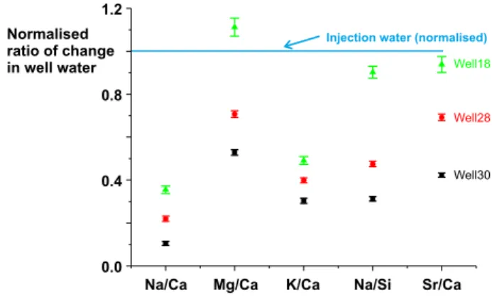
The difference between the element ratios of the injected waters and element ratios of the cations added to the produced waters, calculated by taking the difference between the waters sampled over the last 11 days and those sampled over thefirst 20 days (Fig. 10), shows that the changes in water composition are not explained by increases in the fraction of injection water. Note that injection waters likely to be sampled are those injected prior to the sampling for this project whereas those we analysed were collected during the course of this project. The small rise of injected water cation concentrations during the sample period suggests that concentrations in the older injected waters were correspondingly slightly lower.
This conclusion, that changes in the background brine compositions had a limited impact on the composition of the produced fluids, is supported by the changes of Sr-isotopic ratios in the producedfluids (Fig. 9). The injectionfluids have87Sr/86Sr ratios between 0.71078 and
0.71092, less than well 18 (0.71305 to 0.71394), 28 (0.71137 to 0.71168) and well 30 (0.71309 to 0.71382). Onlyfluids from well 16 (0.710336 to 0.71137) scatter about the composition of the injection fluids. The fluid Sr concentrations in wells 18, 28 and 30 increase by between 66 and 100% over the sampling period. Fig. 11shows the expected trajectories of the initial waters asfluid with the composition of the injection waters is mixed with the initial waters sampled in each well. It is clear that the Sr-isotopic evolution of the wells is dominated by addition of Sr from a source distinct from that of the injectionfluids, presumably from dissolution of minerals.
3.2. Sources offluids: modelling inputs of injection fluids and fluid-mineral reactions
The changes of water compositions resulting from addition of in-jection waters and dissolution or precipitation of minerals may be modelled by mass balance of the stoichiometric cations (c.f.Kampman
Fig. 8. Variation in alkalinity in produced waters over period after CO2injection
com-menced in well 37. Note that wells to the north already producing significant CO2have
high initial alkalinities but these continue to rise. Wells 28 and 30 to the south of well 37 have low initial alkalinities which rise progressively during the sampling period. Data averaged over 4 to 8 day periods.
et al., 2009). The mass balance equation may be written
∑
− = = Cif CiI X α j n j ij 1 (1)where Cif is the final fluid concentration and CiI is the initial fluid
concentration of component, i (mmol/kg).αij is the concentration of
component i in mineral phase j (mole fraction) and Xj is the mass
(mmols) of phase j added to (positive), or precipitated from (negative),
thefluid. Eq.(1)is solved for the n unknowns Xjby the routines inKent
et al. (1990) with the uncertainties on Cif, CiI, andαij propagated
through the calculation. The uncertainties on the initial andfinal fluid compositions are taken as the standard error on the average of thefirst 5fluid samples σ( 5 ), and last 5 fluid samples analysed. The un-certainty on the mineral compositions is taken as the standard error on the mineral microprobe analyses for calcite, plagioclase and biotite (Table 1), as 5% of the concentration for the elemental compositions of
Fig. 9. Variation in Ca, Na, Mg, K, Si, Sr and
87Sr/86Sr ratios in produced waters with time
after commencement of CO2injection in well
37. Data averaged over 4 to 8 day periods. Open symbols are of injection waters.
chlorite and smectite and 0.5% of the components in kaolinite. Solu-tions are illustrated inFig. 12.
The results imply that the chemical evolution of the fluids is dominated by the dissolution of plagioclase, chlorite and biotite and calcite except in Well 16 where calcite modes are within error of zero. Smectite precipitates. The kaolinite mode is within error of zero.
It should be noted thatfluids sampled will be mixtures that range from CO2-saturated fluids flowing close to the CO2penetrating high
permeability layers tofluids far from CO2fingers that are little changed
in composition. Since CO2 will penetrate the highest permeability
layers, the brinesflowing adjacent to the CO2occupying the next most
permeable layers will be preferentially sampled in the produced waters. Thermodynamic modelling offluid-mineral reactions suggests that CO2
-saturatedfluids will initially dissolve calcite but re-precipitate carbo-nates at later times as silicate dissolution raisesfluid alkalinity (e.g.Xu et al., 2007; Dubacq et al., 2012). The decrease in calcite dissolution mode from the least evolvedfluids from Well 30 to the most evolved
from Well 16 is consistent with this prediction and implies that the more reacted CO2-saturatedfluids are precipitating calcite.
3.3. Sr and Sr-isotopic systematics
Sr and87Sr/86Sr ratios put constraints on thefluid and mineral
in-teractions. The Sr-isotopic ratios and Sr and major cation concentra-tions have been determined on whole-rock samples, carbonate leaches and silicate residues and some hand-picked feldspars, lithic and vol-canic clasts from drill core through the Frontier formation in the Salt Creekfield and from outcrops of the Frontier Formation in Wyoming (Figs. 1 & 2, Supplementary data Table S3, Fig. 13). The Sr-isotopic compositions of the carbonate leaches and the carbonate-cemented high CaO whole rock samples imply carbonate87Sr/86Sr ratios of be-tween 0.7075 and 0.7078 which are only marginally higher than sea-water87Sr/86Sr ratios of ~ 0.7074 at the time the Frontier Formation
was deposited. The low-Ca silicate-dominated samples exhibit a wide scatter of87Sr/86Sr ratios of between 0.706 and 0.720 which reflects the heterogeneous source terrain for the Frontier Formation which com-prised contemporary Cordilleran magmatic arc igneous rocks and older Proterozoic and Archaean basement (e.g.May et al., 2013).
The carbonate leaches, silicate residues from leaching, the whole core samples and the lithic and volcanic clasts from core samples from holes 6WC2NW05 and 26WC2NW05 drilled in 1972 at Salt Creek all have low 87Sr/86Sr ratios (0.706 to 0.7088, Table S3) reflecting the
dominance of Cordilleran igneous material in this sediment. Only the feldspar fraction has a slightly higher 87Sr/86Sr ratio of ~ 0.7106. However, from the significantly higher 87Sr/86Sr ratios of the initial
formationfluids (Figs. 9 & 11) and the approximately constant or in-crease in87Sr/86Sr ratios in wells 18, 28 and 30 during the sampling period, we infer that the Sr-isotopic compositions of the silicate mate-rial in the Frontier Formation at Salt Creek exhibits a similar distribu-tion to samples collected from surface outcrops (Fig. 13).
Calculation of the change influid87Sr/86Sr ratios provides a test of the consistency between the calculations of the mineral modes con-sumed and precipitated over the sampling period. The change in cu-mulate mineral inputs or outputs, calculated as inSection 3.2above,
Fig. 10. Molar element ratios of the cations added to the produced waters normalised to the element ratios in the injected waters. The concentration of cations added to waters from each well over the sampling period was calculated by taking the difference between the waters sampled over the last 11 days and those sampled over thefirst 20 days and the 1σ error bars calculated from the standard errors (where n is the number samples) on the set of samples averaged.
Fig. 11. Calculated mixing curves for87Sr/86Sr
ratios between initialfluid samples from wells 18, 28 and 30 as a function of the fraction of initial water added (values below x-axis) com-pared with time evolution of the sampledfluids (days since injection started given above x-axis).
from the difference in chemistry between the initial sampling period and the given sampling period, is illustrated inFig. 14. Precipitation of primary silicates plagioclase or biotite implied by decreasing mode with time coupled with dissolution of smectites as exhibited by Well 30 between days 50 to 75 is most likely explained by mixing of waters with different extents of fluid-mineral reactions. Significant low temperature precipitation of plagioclase or biotite or dissolution of smectites is thought improbable.
The mineral modes may be used to predict the changes influid Sr concentrations and 87Sr/86Sr ratios if their Sr contents and87Sr/86Sr
ratios are known. The Sr content of the carbonate is constrained by the acetic acid leaches of the outcrop samples of the Frontier Formation samples (Table S3) where the samples with > 2000 mmol/kg Ca have Sr/Ca ratios of 1.42 ± 0.10 (1 standard error). The two acetic acid leaches (Sr/Ca = 1.1 and 1.4) lie within this range. The acetic acid leaches of the core samples have rather higher Sr/Ca ratios but most of these have relatively low Ca concentrations (below 350 mmol/kg) and may have leached a minor silicate component. The87Sr/86Sr ratio of the
carbonate component is taken as 0.70755, the mean of the two carbo-nate leaches from samples collected at Raptor Ridge (Fig. 2). The mean of the acetic acid leaches of the core samples is only marginally lower at
0.7074.
Plagioclase probably contains the bulk of the Sr in the silicate fractions in the Wall Creek 2 sandstones. The silicate residues of the low Ca Frontier Formation sandstones and the silicate residues of the core samples have Na/Ca ratios that range between ~ 3 and 12 (mean 5.7) which would correspond to plagioclase anorthite contents between 8 and 23% (mean 15%). The plagioclase feldspars from the core samples (Table S1) exhibit an even wider range of compositions (An 3 to 49%, mean An 21%). It is likely that the feldspars exhibit a corresponding wide range of Sr contents. The Sr concentration of plagioclase is thereforefirst estimated at 3.0 mmol/mol (equivalent to ~460 ppm) from the mean Sr/Na and Na/Ca ratios of the silicate residues of the low-Ca Frontier formation outcrop samples. The other silicate minerals contain small amounts of Sr and their nominal concentrations estimated from literature values are given inTable 1.
The Sr concentration in the sampledfluids is then predicted as a function of time given the changes in cumulate mineral modes dis-solved/precipitated illustrated inFig. 15. To allow for the uncertainty in the plagioclase Sr concentration, the magnitude of the summed si-licate Sr contribution was then adjusted by the factor, f, to give a least-squares bestfit to the measured water Sr concentrations. The factor f is
Table 1
Compositions of minerals used in mass balance calculations.
Calcitea 1σ Plagioclasea 1σ Chloriteb 1σ Biotitea 1σ Kaolinitec 1σ Smectiteb 1σ
SiO2 2.776 0.014 2.688 0.027 2.801 0.024 2.00 0.01 3.55 0.04 Al(O1.5) 1.224 0.014 3.050 0.031 1.419 0.036 2.00 0.02 1.88 0.02 FeO 0.014 0.001 0.007 0.001 1.300 0.065 1.373 0.063 0.35 0.02 MgO 0.006 0.003 0.001 0.000 2.010 0.101 1.109 0.040 0.37 0.02 CaO 0.967 0.006 0.217 0.015 0.015 0.002 0.20 0.01 Na(O0.5) 0.755 0.016 0.050 0.003 0.09 0.00 K(O0.5) 0.039 0.003 0.733 0.025 0.23 0.01 Sr(1000) 1.420 0.100 3.00d 0.41 0.006 0.047e 0.15e 0.23e 87Sr/86Sr 0.7076
aAverage compositions of minerals used in mass balance calculations taken from Table S1 in supplementary information. bAverage chlorite and average continental smectite fromBickle et al. (2015).
cIdeal composition.
dEstimated from residues from leaching Frontier Formation sandstones. eBiotite and clay mineral Sr concentrations taken fromGarçon et al. (2014).
Fig. 12. Mineral inputs (negative for precipita-tion) in mmol/L calculated from difference be-tween initial andfinal fluid samples (Eq.(1)) for the four wells and solved for the components Si-Al-Mg-Ca-Na-K. Error bars are 1σ calculated from uncertainties in mineral andfluid compositions.
then calculated byfinding the value that minimises a χ2variable
∑
⎜ ⎟ = ⎛ ⎝ − ⎞ ⎠ = χ Sr Sr σ ( ) i n Ci Mi Sri 2 1 2 M (2)where SrCiis the Sr concentration calculated from the mineral modes
given their Sr concentrations inTable 1, SrMiis the measured Sr
con-centration andσSrMthe estimated uncertainty of the measured Sr
con-centration. The results are shown inFig. 15and the adjustment factors
vary between 0.43 and 0.62 (0.196 for thefirst period in well 30). This suggests that the estimate of plagioclase Sr concentration of 3 mmol/ mol is high by a factor of two, well within the scatter of Sr/Na ratios. The calculations of the summed silicate Sr input are relatively in-sensitive to the estimate of the carbonate Sr content. For example if this is varied between 0.7 and 2.8 mmol/mol in Well 28 the factors needed to change the silicate input vary only between 0.43 and 0.34. In general the calculated time variation of the Sr concentrations matches the ob-served variations close to the uncertainties in the measured Sr con-centrations estimated from the standard deviation of the sample sets in the time intervals. The most obvious discrepancies are between days ~ 25 and 75 in Well 30. Here the falls in modal plagioclase and biotite and decrease in modal smectite are interpreted to relate to mixing of less reactedfluids as decreases in plagioclase and biotite are very un-likely to result from precipitation of these minerals. The discrepancies most likely reflect heterogeneity of fluid sources and paths within the reservoir as indicated by the modelling of87Sr/86Sr ratios.
Given the bestfit Sr-concentration models, the silicate 87Sr/86Sr ratio which gave a best least-squares fit to the Sr-isotope data was calculated for each of the sampled wells (Fig. 15) by minimising a routine similar to Eq.(2)with Sr concentrations replaced by87Sr/86Sr ratios multiplied by the Sr content. Again the bestfits match the ob-served evolution of87Sr/86Sr ratios well except for the period around
50 days in Well 30 and a comparable period in Well 18.The silicate
87Sr/86Sr ratios deduced from the bestfits range from 0.71053 in Well
16 to 0.71429 in Well 30. These are within the range of silicate Sr-isotopic ratios analysed in the core and outcrop rock samples (0.707 to 0.719).
The calculated water Sr and87Sr/86Sr ratios for Wells 16 and 28
match the observed changes well. The discrepancies in both Sr and
87
Sr/86Sr ratios between days 30 to 75 in Well 30 have been discussed above and are best explained by arrival of waters with a different re-action history. Likewise the rather poorfit to the measured87Sr/86Sr
Fig. 13.87Sr/86Sr ratios versus Ca concentration as a proxy for carbonate content for
whole-rock and 2 leaches of whole-rock samples from outcrops of the Frontier Formation in Wyoming (locations onFig. 2) and leaches and residues from leaching of core through the 2nd Wall Creek sandstone at Salt Creek (localities onFig. 1) (see Supplementary data Table S3). The high-Ca leaches imply carbonate87Sr/86Sr ratios of between 0.7075 and
0.7078 which are marginally higher than seawater87Sr/86Sr ratios of ~ 0.7074 at the time
the Frontier Formation was deposited.
Fig. 14. Cumulative calculated mineral dissolu-tion (+ ve) or precipitadissolu-tion (−ve) from sampled fluids calculated from the difference between each sampling period and the initial sampling period using Eq.(1). Error bars 1σ.
ratios in Well 18 may be explained by waters arriving alongflow paths with differing87Sr/86Sr ratios. Thefits to Well 30's Sr and87Sr/86Sr
profiles is well matched with a change in Sr factor and silicate87Sr/86Sr
ratio at day 52 (Fig. 15). The observed scatter in 87Sr/86Sr ratios in sampled outcrop (Fig. 13) suggests that units in the deltaic 2nd Wall Creek sandstone are distinctly heterogeneous in Sr-isotopic composi-tion. The range of the inferred silicate Sr-isotopic compositions and the apparent relative consistency of inferred isotopic compositions within
the individual wells implies that the injectedfluids are sampling rela-tively coherent beds within the deltaic 2nd Wall Creek sandstone.
The Sr-isotopic ratios confirm the results of the calculations of changes in modal mineralogy that the CO2 injection results in
sig-nificant dissolution of silicate minerals in a relatively short time period.
Fig. 15. Left-hand panels show measuredfluid Sr concentrations (red circles, means of groups of 3 to 5 days of samples with error bars 1 standard error on mean) compared to best least-squares-fit Sr concentrations calculated from mineral modes with silicate Sr concentration adjusted by the factor given on thefigure (black squares). Right-hand panels show bestfit between measured (red circles) and calculated 87Sr/86Sr ratios (black
squares) with silicate87Sr/86Sr ratio adjusted to
value shown. Two solutions are shown for Well 30. One (black squares) shows a profile fit with a single silicate Sr factor and silicate87Sr/86Sr ratio
and the second (stars) afit that derived a silicate Sr factor and87Sr/86Sr ratio for days 4 to 52, then
held these parametersfixed for days 4 to 52 and minimised the misfit in Sr and87Sr/86Sr ratio to
derive bestfit values of the silicate Sr factor and
87Sr/86Sr ratio for days 61 to 151. (For
inter-pretation of the references to color in thisfigure legend, the reader is referred to the web version of this article.)
4. Mineral-fluid reactions and reaction rates
The fundamental process controlling the rates offluid-mineral re-actions is the rate at which CO2dissolves in the formation brines. In this
experiment withfluids sampled at surface after they have undergone significant decompression, direct measurements of fluid CO2contents
are not possible. Below we make thermodynamic estimates of the un-degassedfluid compositions based on two approaches. 1) Calcite dis-solution reaction rates are fast and it is possible to calculate thefluid partial CO2 pressure for equilibrium with calcite. 2) The observed
plagioclase dissolution implies significant fluid undersaturation which again is a function offluid CO2partial pressure.
4.1. Approach to calcite-fluid equilibrium
The approach of calcite to equilibrium with the formation brines is governed by the degree of thermodynamic disequilibrium between the calcite and brine and the rate at which CO2is being transported by
either diffusion or advection through the brine. The dissolution rate for calcite (RT, mol·m− 2·s− 1) may be expressed as
⎜ ⎟ = = ⎡ ⎣ ⎢ −⎛ ⎝ ⎞ ⎠ ⎤ ⎦ ⎥ R K f ΔG K Ω K ( ) 1 T R R sp n 0 (3) where KR is a rate constant (mol·m− 2·s− 1), which is in general a
function of temperature and fluid composition and ΔG (kJ/mol) is a measure of the distance from thermodynamic equilibrium between calcite and the fluid. Transition state theory (e.g. Aagaard and Helegeson, 1982) suggests thatΔG has the form in Eq.(3)whereΩ is the activity product and Ksp0 is the solubility product (equilibrium
constant) but this is uncertain (e.g. Hellmann and Tisserand, 2006). However in most published expressions f(ΔG) tends to a constant far from equilibrium and for calcite n ~ 1.
The rate constant, KR, for calcite is a function of pH, temperature,
CO2 partial pressure and other components in the fluid phase.
Pokrovsky et al. (2009) note that when recalculated to constant pH = 5, calcite dissolution rates exhibit a maximum at ~ 4 MPa and are only weakly dependent on temperature. The rates range between 1.8 × 10− 5and 3 × 10− 4mol·m− 2·s− 1.
The change in Ca concentration (Ca, mol·m− 3) of thefluid with time (t, s) due to surface dissolution of calcite can be written
⎜ ⎟ ∂ ∂ = ⎛ ⎝ − ⎞ ⎠ φ t K α Ω K Ca 1 R sp0 (4)
whereϕ is porosity and α is reactive surface area of calcite (m2/m3) in the rock. The ratio of the activity product to solubility product (Ω/Ksp0)
is approximately proportional to fluid Ca content ratioed to the Ca content in equilibrium with calcite (Caeq) (Fig. 16) which allows Eq.(4)
to be rewritten ∂ ′ ∂t =K − ′ Ca " (1 Ca ) (5) where Ca′ = Ca/Caeqand K″ (s− 1) is given by
=
K K α
φ Ca
" R .
eq (6)
K″ = 0.087 s− 1for a far-from-equilibrium calcite dissolution rate of
KR= 1.8 × 10− 5mol·m− 2·s− 1(Pokrovsky et al., 2009), 1 vol% calcite
in the rock with a surface area of ~ 2.5 × 10⁴m2/m3 (chosen as a minimal calcite content), porosity ϕ = 0.2 and equilibrium Ca con-centration (Caeq) of 26 mol/m3.
The dominant transport of CO2and Ca in thefluid may be by
dif-fusion (e.g. close to CO2fingers) or by advection in the flowing brines.
The differential equation describing diffusion and reaction with linear kinetics (c.f.Lichtner, 1988) is ∂ ∂ = ∂ ∂ +
(
−)
φ t φD τ x K α Ca Ca 1 CaCa R eq 2 2 (7)Non-dimensionalising Eq.(7)by the transformations. = ′ Ca Ca Caeq (8) = ′ x x l (9) = ′ t t l D 2 (10) where Caeqis thefluid Ca concentration in equilibrium with CO2
sa-turatedfluid, l is an appropriate length scale (e.g. transport distance) and D is the diffusion coefficient, gives
∂ ′ ∂ ′ = ∂ ′ ∂ ′ + − ′ Ca t Ca x ND (1 Ca) diff 2 2 (11)
where, the dimensionless constant, a Damköhler Number for diffusion, NDdiff, is given by = N τ K α l φ DCa D diff R eq 2 (12)
For the parameters given above and l > 0.25 mm, NDdiff> 10, the
condition for reaction to be fast compared with diffusion (e.g.Bickle, 1992). This short transport distance is consistent with the experimental observation that calcite dissolution experiments are transport con-trolled at pH < 5 (Pokrovsky et al., 2009) and implies that, while calcite is present in the reservoir,fluids will be close to equilibrium with calcite where CO2is transported by diffusion.
For advective displacements, transport and reaction may be de-scribed by ∂ ∂ = − ∂ ∂ +
(
−)
φ t ϖφ x K α Ca Ca 1 CaCa R eq (13)whereϖ is the net fluid pore velocity. Non-dimensionalising Eq.(13)
using Eqs. (8) and (9) but with time scaled as
= ′ t t l ϖφ (14) transforms Eq.(13)to ∂ ′ ∂ ′ = − ∂ ′ ∂ ′ + − ′ t x N Ca Ca (1 Ca ) D (15)
where the Damköhler Number for advection, NDAis given by
Fig. 16. Variation of calcite saturation state as a function offluid Ca′ concentration (Ca′ = Ca/Caeq) calculated for initialfluid sample SCR-7-28 saturated in CO2at 10 MPa
= N K α l ϖ φ Ca DA R eq (16)
The maximum brine velocities at Salt Creek are ~ 5 m/day given the permeabilities (Fig. 4), driving pressure gradients (Fig. 5) and for the viscosity of supercritical CO2and thereforeNDA > 10 for l > ~ 5 mm.
Thereforefluids will approach saturation with calcite after flowing only 5 mm.
The conclusion is that on the length and velocity scales of the Salt Creek experiment transport rates are sufficiently slow that the fluids should remain close to equilibrium with calcite where calcite is present. It is therefore possible to estimate minimumfluid CO2contents and pH
at reservoir conditions from thefluid chemistries and alkalinities pre-suming that calcite precipitation is limited as thefluids decompress in the production wells.
4.2. Alkalinity as a function of PCO2at calcite saturation
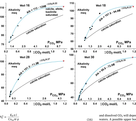
Fig. 17 illustrates the variation in alkalinity calculated using PHREEQC as a function of total CO2and PCO2for thefluids from wells
16, 18, 28 and 30 assuming that thefluids were in equilibrium with calcite at a reservoir pressure of 10 MPa and temperature of 50 °C. Also shown is the theoretical increase in alkalinity if the initialfluid sample (average of first 5 samples) is reacted only with calcite as the CO2
partial pressure is increased. The deviation from the simple calcite sa-turation line is a consequence of the dissolution of silicate components in addition to calcite consistent with the modelling of thefluid com-positions discussed above. This reduces the inferred CO2contents over
those predicted from the increase in alkalinity being due to dissolution only of calcite.
One approximation with the use of the empirical curves calculated byfits to the sampled waters to calculate the expected alkalinity as a function of dissolved CO2, is that the sampled waters are averages of the
well waters over the whole depth of the 2nd Wall Creek which will range from CO2-saturated to unaffected by the newly injected CO2. The
sampled waters therefore are restricted to lower dissolved CO2contents
and alkalinities than the full range. The relationship between alkalinity
and dissolved CO2will depend on the chemistry of these more saturated
waters. A possible upper bound is shown by the alkalinity of the initial fluid brought to equilibrium with calcite, albite and kaolinite (Fig. 17). It should also be noted that mixing offluids with the observed non-linear alkalinity-total CO2trends likely results in the mixture becoming
undersaturated in calcite and/or silicate minerals.
4.3. Magnitude and kinetics offluid-mineral reactions
The modal calculations (Fig. 12) indicate that the sampledfluids dissolve about 20 mmol plagioclase per litre on average over the 150 day sampling period. Again it is important to note that this is an average of all thefluids sampled which will range from those unreacted to those with most reaction, albeit biased towards the latter. An ‘average’ dissolution rate for the silicate minerals may be calculated given estimates of their surface areas, the porosity and the duration of the alteration. Surface areas of plagioclase measured by gas absorption (BET), are ~ 1 m2/g. The porosity of the more permeable layers is ~ 20% and the plagioclase mode in Frontier Formation samples is ~ 15% by volume (e.g.Dutton et al., 2000). These parameters give a mean dissolution rate over the 150 days of injection of ~ 10− 12mol·m− 2·s− 1. The major uncertainty is the estimate of plagi-oclase surface area for which 90% of the published measurements vary by a factor of 5 (see compilation in White and Brantley, 2003) and generally increase as dissolution reactions progress. The rate of 10− 12mol·m− 2·s− 1is at the lower end of the range of far-from-equi-librium rates determined by many laboratory experiments at surface conditions. The 2nd Wall Creek Formation at Salt Creek has a tem-perature of ~ 50 °C which would increase plagioclase dissolution rates by a factor of ~ 7 over rates at 25 °C given an activation energy of ~ 60 kJ·mol− 1 as estimated by Hellmann and Tisserand (2006) and
Gruber et al. (2016). The compilation of plagioclase dissolution rates measured in laboratory experiments by White and Brantley (2003), adjusted to 50 °C, range from 2.5 × 10− 12 to 10− 10mol·m− 2·s− 1.
Gruber et al. (2016) measured dissolution rate of albite at 6 × 10− 12mol·m− 2·s− 1at 50 °C.
It is of interest to estimate the CO2partial pressures necessary for
Fig. 17. Variation of alkalinity with total dis-solved CO2(ΣCO2) forfluids from wells (points
give average of groups of 5 samples) where total CO2is calculated from assumption thatfluids are
in equilibrium with calcite at reservoir pressure of 10 MPa and temperature of 50 °C. Lines la-belled‘calcite saturation’ show evolution of in-itialfluid (average of first five samples) as CO2
partial pressure is increased while maintaining equilibrium with only calcite. Red triangle shows alkalinity of initialfluid brought to equilibrium with calcite, albite and kaolinite. Calculated using PHREEQC. Blue lines are bestfit to well sample alkalinity data with calcite-albite-kaoli-nite saturated compositionfixing high ΣCO2end
of line. (For interpretation of the references to color in thisfigure legend, the reader is referred to the web version of this article.)
the plagioclase to be‘far-from-equilibrium’ generally taken as ΔG for the plagioclase dissolution reaction of less than ~ < −50 kJ/mol. The extent of thermodynamic disequilibrium between plagioclase and the averagefluid sampled over days 148 to 153 from well 28 is illustrated inFig. 18as a function of the CO2partial pressure for low albite, high
albite and high albite feldspar solid solutions with 20% and 40% an-orthite. The deviation from equilibrium,ΔG in kJ/mol is given by (e.g.
Drever, 1997) ⎜ ⎟ = ⎛ ⎝ ⎞ ⎠ ΔG RT IAP K ln eq (17)
where R is the gas constant, T temperature (K), IAP is the ion activity product and Keqis the equilibrium constant for the plagioclase
dis-solution reaction + − + + = + − + − + + − − + + + + + x x x x x x Na Ca Al Si O 2(2 ). H (2 4). H O . Na (1 ). Ca (2 ). Al(OH) (2 ). H SiO x x x x (1 ) (2 ) (2 ) 8 2 2 2 4 4 (18) where x is the mol fraction albite. The equilibrium constant, Keq, is
calculated using the software package SUPCRTBL (Zimmer et al., 2016), an updated version of SUPCRT92 (Johnson et al., 1992). The thermodynamic properties of plagioclase solid-solutions are taken from
Arnorsson and Stefansson (1999). The ion activity product is calculated using PHREEQC (version 3.3.8) with the PHREEQC data base and the thermodynamic properties of Al-species taken fromTagirov and Schott (2001). It is of interest that the calculated activities of Al-fluoride
species in the brines become dominant at the reservoir conditions. For example in the 148–153 fluid from well 28 the calculated activity of Al (OH)2+ is ~ 1.6 × 10− 7 at surface conditions decreasing to
~ 2 × 10− 8at a CO2pressure of 10 MPa. In contrast the activity of
AlF2+increases from ~ 2 × 10− 9at surface conditions to ~ 3 × 10− 6
at 10 MPa CO2pressure.
The mean plagioclase composition from the core samples is ~ An 21% (Table 1) and of the outcrop samples ~ An 15% (from Na/Ca ratios) and such plagioclases are just saturated (ΔG ~ 0) at calcite sa-turation in the well 28 samples (initial andfinal sample illustrated in
Fig. 18). The more marked degrees of undersaturation illustrated in
Fig. 18, required to drive plagioclase dissolution at the inferred rate implies higher CO2 partial pressures at which calcite would also be
undersaturated. However the uncertainties in the thermodynamic data are not well constrained and comparison of the different data sets PHREEQC.dat and lnll.dat with and without modified Al species gives a
range of the order ± 8 kJ/mol for plagioclase. This, coupled with the uncertainties in plagioclase surface areas and plagioclase dissolution rates means that it is not possible to make a definitive conclusion as to the apparent discrepancy between CO2partial pressures inferred from
calcite saturation and plagioclase dissolution rates. Alternatively it is possible that the brines precipitate significant carbonate on decom-pression or that the brines may be undersaturated in calcite because the rocks are heterogenous and some of theflow paths are calcite free (c.f.
Fig. 13).
5. Conclusions
Sampling offluids from sites where CO2is injected for enhanced oil
recovery enables evaluation of fluid-rock interactions, rates of CO2
dissolution in the sampled brines and gives a measurement of the het-erogeneity of the formations sampled. The sampling of brines from production wells for six months after commencement of a phase of CO2
injection into the 2nd Wall Creek member at the Salt Creek oilfield, Wyoming, reveals marked increases in the concentrations of major cations over weeks, highlighting the reactivity of the relatively im-mature sandstone to CO2-richfluids. The concentrations of the anions
Cl and Br remained unchanged which implies that the changes do not reflect heterogeneity in previously injected waters. Marked decreases in F during the sampling may reflect the volatility of SiF4which partitions
into the CO2phase. Modelling the mineral reactions from the changes
in cation chemistry indicates that mineral dissolution is dominated by plagioclase, with subsidiary biotite, calcite and chlorite. The silicate mineral dissolution is buffered by precipitation of the clay minerals.
The increase in Sr and87Sr/86Sr ratios with time in the sampled
fluids is consistent with the bulk of the Sr being supplied from plagio-clase with elevated87Sr/86Sr ratios and confirms the importance of dissolution of silicate minerals over the relatively short timescale in this experiment. The calculated87Sr/86Sr ratios (0.7106 to 0.7156) of the
silicate inputs lie within the range of the87Sr/86Sr ratios (0.708 to 0.720) measured in the silicate fractions of core and outcrop samples from the Frontier Formation. The range of Sr-isotopic ratios across the different production wells demonstrates that flow paths within the re-servoir sample horizons with distinct isotopic compositions, a conclu-sion consistent with the strongly heterogeneous permeabilities within the formation coupled with the marked Sr-isotopic heterogeneities. The chemical and isotopic variations in the time series from well 30 imply arrival offluids from a different flow path with different extents of mineral-fluid reactions part way through the sampling period. These results attest to the sensitivity of geochemical tracers toflow paths and their variations, at least in formations with suitably reactive mineral assemblages.
The calculated rates of diffusion of CO2into brines and advection of
CO2byflow rates within the formation are sufficiently slow that the
fluids are expected to remain close to equilibrium with calcite, given its presence in the reservoir (calcite saturation is predicted after CO2
-en-richedfluids migrated 5 mm into the reservoir). This allows estimation of the CO2contents of thefluids in the formation prior to their ascent
and degassing in the production wells before sampling. Another po-tential constraint on the reservoirfluid CO2contents is the observation
that the average rate of plagioclase dissolution is ~ 10− 12mol·m− 2·s− 1 (with uncertainty in plagioclase surface area of ~ a factor offive). This dissolution rate is relatively fast, especially considering that the sam-pledfluids represent an average of all fluids from the production well. These will range from those close to injected CO2and correspondingly
CO2-rich to those distant from penetrating CO2fingers and thus
un-saturated, albeit that the sampling will be biased by the higherfluxes from the more permeable horizons adjacent to the CO2 fingers.
Formation CO2partial pressures in samples from the end of the
sam-pling period estimated to drive the plagioclase dissolution at rates of 10− 12mol·m− 2·s− 1 (with far-from-equilibrium rates of ~ 1.6 × 10− 12mol·m− 2·s− 1) are ~ 5 MPa compared with about
Fig. 18.ΔG for the plagioclase dissolution reaction calculated for Ab100, Ab80and Ab60
high albite and low albite (see Eqs.(17) & (18)) at a temperature of 50 °C and pressure of 10 MPa as a function of CO2partial pressure for the average brine sample from days 148
to153 from well 28. This sample is calcite saturated at a PCO2of 1.5 MPa (solid arrow).
Dashed line showsΔG for plagioclase Ab80for the initial brine sample (days 1–7) which is