HAL Id: hal-02150738
https://hal.archives-ouvertes.fr/hal-02150738
Submitted on 7 Jun 2019
HAL is a multi-disciplinary open access
archive for the deposit and dissemination of sci-entific research documents, whether they are pub-lished or not. The documents may come from teaching and research institutions in France or abroad, or from public or private research centers.
L’archive ouverte pluridisciplinaire HAL, est destinée au dépôt et à la diffusion de documents scientifiques de niveau recherche, publiés ou non, émanant des établissements d’enseignement et de recherche français ou étrangers, des laboratoires publics ou privés.
Bedding-parallel stylolites as a tool to unravel maximum
burial depth in sedimentary basins: application to
Middle Jurassic carbonate reservoirs in the Paris basin
Nicolas Beaudoin, M Gasparrini, M.-E David, O. Lacombe, D. Koehn
To cite this version:
Nicolas Beaudoin, M Gasparrini, M.-E David, O. Lacombe, D. Koehn. Bedding-parallel stylolites as a tool to unravel maximum burial depth in sedimentary basins: application to Middle Jurassic carbonate reservoirs in the Paris basin. Geological Society of America Bulletin, Geological Society of America, 2019, �10.1130/B32064.1�. �hal-02150738�
Bedding-parallel stylolites as a tool to unravel maximum burial depth in sedimentary basins: 1
application to Middle Jurassic carbonate reservoirs in the Paris basin 2
3
N. Beaudoin (1,2)*, M. Gasparrini (3), M.-E. David (3,4), O. Lacombe (4) and D. Koehn (2) 4
5
(1) Laboratoire des Fluides Complexes et leurs Réservoirs-IPRA, E2S-UPPA, Total, CNRS, Université de 6
Pau et des Pays de l'Adour, UMR5150, Pau, France 7
(2) School of Geographical and Earth Sciences, University of Glasgow, Gregory Building, Lilybank 8
Gardens, G12 8QQ, Glasgow, UK; 9
(3) IFP Energies nouvelles, 1 and 4 av. de Bois-Préau, 92852 Rueil-Malmaison, France 10
(4) Sorbonne Université, CNRS-INSU, Institut des Sciences de la Terre de Paris, ISTeP UMR 7193, F-11
75005 Paris, France. 12
*Corresponding author: [email protected] 13
Keywords: Burial depth, stress inversion, paleopiezometry, stylolites, carbonate reservoirs, Paris basin 14
Abstract 15
In recent years stylolites, which are rough dissolution surfaces commonly found in carbonates, have 16
been used for paleopiezometry estimates. The Stylolite Roughness Inversion Technique (SRIT) applied 17
on sedimentary bedding-parallel stylolites (BPS) grants access to the maximum principal vertical stress 18
experienced by the host carbonates and thus to their maximum burial paleo-depth. This study reports 19
the results of SRIT applied to a BPS stylolite population hosted in carbonate platform reservoirs of the 20
Paris basin sub-surface (France). Middle Jurassic carbonates from two well cores from the depocenter 21
and margin of the basin, for which the burial and thermal history are known, based on a thermally 22
calibrated 3D basin model, were analysed. By defining a consistency criterion and using two signal 23
treatment methods, we propose a new approach to select which BPS can be reliably used to 24
reconstruct the maximum vertical stress undergone by the host carbonates, which then can be 25
converted into maximum burial depth. The study of a BPS population shows that there is a control 26
operated by the host rock texture and the stylolite morphology on the burial depth recorded. 27
Especially suture and sharp peak BPS are better suited to estimate the real maximum depth, whereas 28
seismogram pinning BPS record preferentially intermediate depths. Median values of maximum depth 29
derived from our dataset (1.3 and 1.7 km for the margin and depocenter cores, respectively) are in 30
line with maximum burial estimates provided by conventional basin modelling (1450 and 1800 m, 31
respectively), thus showing that SRIT is a standalone robust depth gauge in sedimentary basins, 32
provided sample selection and data treatment are carried out in a rigorous and thoughtful manner. 33
1. Introduction 34
Stylolites are localized rough dissolution surfaces that are encountered in all sedimentary rock types 35
(Alvarez et al., 1978; Koehn et al., 2007) and are particularly common in carbonates, which represent 36
significant host rocks of natural resources (water, oil, gas, ores) worldwide. The chemical compaction 37
process occurring during burial and/or tectonic loading significantly affects the physical properties of 38
carbonate reservoirs by reducing porosity (Raynaud and Carrio-Schaffhauser, 1992; Ehrenberg, 2006). 39
The occurrence of sedimentary stylolites, usually oriented parallel to bedding (bedding-parallel 40
stylolites or BPS) impacts fluid flows, by forming either barriers or drains in reservoir rocks (Koepnick, 41
1987; Ehrenberg et al., 2006; Hassan, 2007; Heap et al., 2013; Baud et al., 2016; Koehn et al., 2016; 42
Bruna et al., 2018; Martín-Martín et al., 2018, Toussaint et al., 2018). The characteristic teeth of 43
stylolites, oriented oblique or normal to the dissolution surface, are related to the distribution of 44
insoluble elements in the host rock, leading to local pinning under an oriented applied stress (Fletcher 45
and Pollard, 1981; Merino et al., 1983; Koehn et al., 2007). Various genetic models were proposed to 46
account for the initial localization of dissolution along a surface and the lateral propagation of BPS. 47
The pressure-solution model (Merino et al., 1983) considers that stylolites are related to local 48
dissolution under an applied stress field and that the lateral propagation is controlled by the stress 49
concentration at stylolite’s tips (anticrack model, Fletcher and Pollard (1981)). This model was 50
questioned by Aharonov and Katsman (2009) because stress concentrations at the tips of a stylolite 51
are relaxed once the stylolite itself supports the applied stress. The clay-enhanced dissolution model 52
(Bjorkum, 1996; Oelkers et al., 1996; Walderhaug et al., 2006), originally developed for quartz-mica 53
interfaces, considers that stylolites develop on a clay-rich interface related to an electrochemical 54
potential at the contact between the host rock and the clay. The clay-enhanced model can explain the 55
localisation of dissolution at a surface and also the lateral propagation of stylolite planes (Aharonov 56
and Katsman, 2009) along clay-rich areas. Both the pressure-solution and the clay-enhanced models 57
can be combined where clay particles, that accumulated during the host rock dissolution under 58
applied stress, enhance the dissolution kinetics (Renard et al., 2001). Since stylolites are features that 59
form during chemical compaction, which is a function of the sediment overburden and since the tooth 60
flanks are parallel to maximum the principal compressive stress, the stress clearly plays a key role in 61
the formation of these features. In carbonates, the type of facies (chiefly dependent on depositional 62
texture, primary mineralogy and abundance of allochems, mud and pores), the morphology (Andrews 63
and Railsback, 1997), the presence of clays and organic matter, as well as the vertical heterogeneity 64
of the strata and the applied stress are the main parameters that govern stylolitization (Shinn and 65
Robbin, 1983; Bathurst, 1987, 1991; Aharonov and Katsman, 2009; Koehn et al., 2012; Vandeginste 66
and John, 2013; Koehn et al., 2016). Today still, assessing the mechanisms that govern BPS 67
development as well as the quantification of the stress experienced by the stylolite host rock are key 68
points to understand sedimentary basin evolution aiming at improving geological simulations at both 69
the basin and the reservoir scales (Braithwaite, 1988; Andrade Ramos, 2000; Gratier et al., 2005; 70
Peacock and Azzam, 2006; Baron and Parnell, 2007; Benedicto and Schultz, 2010; Angheluta et al., 71
2012; Koehn et al., 2012; Heap et al., 2013; Khair et al., 2013, 2015; Baud et al., 2016; Bertotti et al., 72
2017). 73
In addition to being used to estimate chemical compaction during burial diagenesis (Peacock and 74
Azzam, 2006; Angheluta et al., 2012; Koehn et al., 2016) and to refine deformation history of strata 75
(Benedicto and Schultz, 2010; Tavani et al., 2006, 2015), stylolites have been used to access the 76
magnitude of applied stress. The Stylolite Roughness Inversion Technique (SRIT, Schmittbuhl et al., 77
2004) is based on a signal analysis of the stylolite’s roughness. Successive studies (Renard, 2004; 78
Schmittbuhl et al., 2004; Brouste et al., 2007; Ebner et al., 2009a; Ebner et al., 2009b; Croizé et al., 79
2010; Ebner et al., 2010a; Rolland et al., 2012, Koehn et al., 2012) established SRIT as a novel 80
paleopiezometric technique, independent from dissolution kinetics, temperature and fluid pressure, 81
that quantifies (1) the maximum vertical stress at the time the dissolution along the stylolite plane 82
stops, and thus the corresponding burial depth, if the method is applied to sedimentary stylolites 83
(Brouste et al., 2007; Ebner et al., 2009b 2010a, 2010b; Rolland et al., 2014; Beaudoin et al., 2016; 84
Bertotti et al., 2017), and (2) the complete stress tensor, by applying SRIT on coeval sedimentary and 85
tectonic stylolites (Ebner et al., 2010a; Rolland et al., 2014; Beaudoin et al., 2016). SRIT relies on the 86
self-affine properties of the stylolite plane roughness to access the magnitude of the stress oriented 87
normal to the stylolite plane (considering a 2D signal, Schmittbuhl et al., 2004) or of both the stresses 88
oriented normal and parallel to the stylolite plane (considering a 3D signal, Ebner et al., 2010b). Even 89
if SRIT was successfully applied to BPS in natural samples and the method reproduced applied external 90
stresses in numerical simulations (Koehn et al., 2012), the magnitudes of the vertical stress 91
reconstructed in published studies show a variability, leading authors to either use averaged values 92
(Bertotti et al., 2017), or to discuss what this variability can mean. Indeed, variable SRIT results were 93
accounted for by considering elastic parameters of the host rock (Rolland et al., 2014), morphological 94
sensitivity of the roughness (Brouste et al., 2007), polyphase burial history or methodological 95
limitations (Beaudoin et al., 2016). 96
This contribution proposes a statistical appraisal of SRIT applied to a natural BPS population in a weakly 97
tectonized sedimentary basin. Our approach aims at inverting BPS from two cores of the Paris basin 98
sub-surface (Fig. 1) where Middle Jurassic carbonates suffered different maximum burial depth. We 99
use established signal treatment methods (Simonsen et al., 1998; Renard et al., 2004; Ebner et al., 100
2009b), Fourier Power Spectrum (FPS) and Average Wavelet Coefficient (AWC), to reconstruct the 101
maximum vertical stress recorded by BPS, and hence the maximum burial depth undergone by the 102
host carbonates. The SRIT is conducted regarding the stylolite morphology, following the recent 103
classification proposed in Koehn et al., (2016), and regarding the depositional texture of the host-rock. 104
On the basis of the direct comparison between the inversion results and the known maximum burial 105
depth independently provided by 3D basin modeling (Fig. 2), we develop a data treatment workflow 106
for BPS populations that show how to use SRIT to access to the maximum burial depth experienced 107
by strata as a reliable paleopiezometer in future studies. 108
2. Stylolite Roughness Inversion Technique (SRIT) 109
a. Principles of the technique 110
SRIT assumes that the stylolite roughness results from a competition between (1) a destabilizing 111
(roughening) force due to pinning particles on the stylolite surface, that resists dissolution in specific 112
locations, locally increasing the Helmholtz free energy and producing peaks and teeth; and (2) two 113
stabilizing (smoothening) forces, long-range elastic forces and local surface tension, that tend to 114
reduce the Helmholtz free energy of the solid, leading to flattening of the surface by localizing 115
dissolution on areas of local roughness (Schmittbuhl et al., 2004; Koehn et al., 2007, Rolland et al., 116
2012). The stylolite roughness displays self-affine properties, i.e., a geometry that is invariant across 117
a range of scales typically with a different scaling in x than in y so that the surface becomes rougher 118
towards smaller scales. The two stabilizing forces are efficient at different spatial scales so that two 119
regimes can be defined: an elastic energy-dominated regime at a large-scale (above mm, typically), 120
and a surface energy-dominated regime at a small-scale (below mm, Schmittbuhl et al., 2004). Each 121
of the stabilizing forces is characterized by a specific roughness coefficient (called Hurst coefficient) 122
that can be determined by conducting a Fast Fourier Transform, Wavelet Analysis or applying a 123
Correlation Function on the roughness profile along a stylolite. This Hurst coefficient has been 124
extensively documented in natural stylolites (Brouste et al., 2007), and the transition from one 125
stabilizing force spatial scale domain to the other is called the crossover length (Lc). Lc is related to 126
both the mean stress and differential stress the rocks sustained during stylolite growth according to 127 Schmittbuhl et al. (2004) 128 Lc = γE βσmσd , (1) 129
where the cross-over length Lc (mm) is linked to the Young’s modulus E (Pa), to the solid-fluid 130
interfacial energy γ (J.m-2), to the dimensionless constant β = υ(1 − 2υ)/π with υ being the Poisson’s
131
ratio, and to the mean and differential stress, σm and σd, respectively. It is noteworthy that this
equation is valid considering that the stylolite localized along a water-rock interface, and that the 133
mechanical properties of the dissolved rock remain constant during dissolution. Provided the rock 134
properties are known, SRIT therefore grants access to the stress acting normal to the BPS plane. 135
136
b. Measurement methodology 137
The roughness signal was studied following the approach described in Schmittbuhl et al. (2004) and 138
Ebner et al. (2009b). Surfaces of core samples, cut perpendicular to the stylolite planes, were hand-139
polished using abrasive grinding papers from coarse (250 µm) to extra fine (2.5 µm) allowing gentle 140
polishing in order to prevent any alteration of the material. Once the stylolite track visually contrasts 141
with the host rock, the surface is scanned in 2D at a resolution of 12800 dpi. Stylolite tracks were hand-142
drawn using a drawing software (GIMP) with a 5 pt. thick line. We then used scripts presented in Ebner 143
et al. (2009b) to rotate the stylolite plane back to horizontal. The resulting 1D signal was analyzed 144
using the Fourier Power Spectrum (FPS; Renard et al., 2004) and the Average Wavelet Coefficient 145
(AWC) methods with Daubechies D4 wavelets (Simonsen et al., 1998; Ebner et al., 2009b). Both 146
methods have been applied to roughness 1-D profiles, and returned similar results (Simonsen et al., 147
1998; Candela et al., 2009; Ebner et al., 2009b). The general signal analysis resolves around the self-148
affine properties of the stylolite roughness, defined as the height difference Δh between two points 149
of the rough surface separated by a distance Δx. A self-affine signal is characterized by Δh≈ΔxH, where
150
H is the Hurst coefficient. In the case of a FPS analysis, in which the signal is considered as a sum of 151
periodic sinuses and cosinuses, the wave number k (mm-1) and the squared Fourier transform modulus
152
P(k) are related as 𝑃(𝑘) = 𝑘2𝐻+1. In the case of an AWC analysis, in which the signal is reconstructed 153
in a sum of different wavelets, starting with a mother function (Simonsen et al., 1998), the scale a 154
(mm) and the averaged wavelet coefficient W(a) are related as 𝑊(𝑎) = 𝑎𝐻+0.5. For each method, it 155
is possible to access the H coefficient based on the slope that links the data, picked following a binning 156
interval, on a log-log plot, and using the relations reported above. In an ideal case, two straight lines 157
should be traceable on log-log plots, a steep line at the lower scale values, characterized by a H of 1 158
(corresponding to surface energy), and a gentle slope line at the higher scale values, characterized by 159
a H of 0.5 (corresponding to elastic energy). The observation scale (k for FPS, a for AWC) at which the 160
two slopes intersect is the crossover length Lc that is related to the vertical stress for sedimentary 161
stylolites. In order to reduce uncertainty on Lc, we fit the line that goes through the maximum of 162
binned data points and use slopes that satisfy the theoretical H coefficients. To estimate the error on 163
the Lc value obtained, we consider a domain of transition between the two regimes using the scale at 164
which there is a clear separation of the two slopes on each side of the intersection (log-log plots of 165
Fig. 6). This domain represents an error graphically evaluated from ±4% to ± 10% of the Lc, depending 166
on where the Lc sits on the log-log plot. It is noteworthy that the SRIT is independent of the dissolution 167
kinetics, the surrounding fluid pressure and the amount of dissolution. Thus, the amount of chemical 168
compaction accommodated by the stylolites is beyond the scope of this study. 169
170
c. BPS inversion for vertical stress and depth assessment 171
For BPS, we can assume a zero horizontal displacement in the stylolite plane, corresponding to a 172
perfect isotropy of the horizontal principal stress, such as σv>σH=σh (σH and σh are the notation for the
173
maximum and minimum horizontal principal stress, respectively), leading to the simplification of the 174 equation (1) as: 175 σv2= γE κLc , (2) 176 with κ = ν 3π× ( (1−2ν)2(1+ν)
(1−ν)2 ) (Koehn et al., 2012). Finally, the depth h is obtained using σv = ρgh, with
177
ρ the rock density and g the gravitational field acceleration. In our study, we use the classic solid-fluid 178
interfacial energy value for calcite (ν=0.27 J.m-2), the averaged mechanical parameters obtained from
179
mechanical testing conducted on the Comblanchien carbonate formations (Bemer and Lombar, 2010): 180
a Poisson’s ratio of 0.22, a Young’s modulus of 34 GPa, and a density for carbonates of 2700 g.cm-3.
181
Considering the error on the Lc values, and the range of the mechanical parameters (E = [31 – 36] GPa, 182
Poisson’s ratio [0.21-0.23]), the uncertainty on the inversion results is ±10 %. 183
184
3. Case study of the Middle Jurassic carbonates of the Paris basin 185
a. Geological and thermal history 186
The Paris basin is a Meso-Cenozoic intracratonic basin which initiated in late Carboniferous and 187
Permo-Triassic times in response to the extensional collapse of the thickened Variscan lithosphere and 188
reactivation of inherited Variscan structures (Perrodon and Zabek, 1990; Guillocheau et al., 2000; Le 189
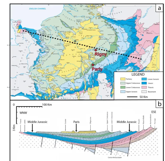
Solleuz et al., 2004; Averbuch and Piromallo, 2012). It is mainly filled by Mesozoic sediments lying 190
uncomformably on a Paleozoic basement (Fig. 1), with the whole sedimentary column (from Triassic 191
to Tertiary) reaching about 3000m of thickness in the central part of the basin (Fig. 1). During Mesozoic 192
times the Paris basin experienced a simple burial history, punctuated by periods of rapid subsidence 193
in the Jurassic and Late Cretaceous and of minor uplifts. A major tectonic inversion occurred at the 194
Mesozoic-Cenozoic boundary, which led to the main uplift phase causing the exposure of the entire 195
basin (Brunet and Le Pichon, 1982; Guillocheau et al., 2000; Barbarand et al., 2013). At the southern 196
and eastern basin margins evidence for three Cenozoic tectonic events were recorded: the Pyrenean 197
orogeny (N-S compression; Eocene), the opening of the Bresse and Rhine grabens related to the West 198
European Rifting (E-W to WNW-ESE extension; late Eocene – Oligocene) and the Alpine orogeny 199
(WNW-ESE compression; Miocene-Pliocene) (Lacombe et al., 1990, 1993, 1994; Guillocheau et al., 200
2000; Andre et al., 2010).The sedimentary succession has been extensively explored for oil and gas 201
resources (Espitalié et al., 1988; Delmas et al., 2002, 2010), which migrated mostly in Late Cretaceous 202
time into reservoir rocks from different stratigraphic intervals (mainly Upper Triassic, Middle Jurassic 203
and Lower Cretaceous; Wendebourg and Lamiraux, 2002; Delmas et al., 2002, 2010). 204
205
In this study, a 3D basin model for the Paris basin was used to extract the burial and thermal history 206
of the studied cores. The original geometric model was constructed with the TemisFlow software for 207
basin modeling, (Teles et al., 2014) and was recently improved by considering a lithospheric model for 208
heat transfer, and by reconstructing paleobathymetry maps and eroded thicknesses through time 209
(Torelli, 2018) (Fig. 2). Thermal calibration was accomplished with present-day bottom hole 210
temperatures (BHT) and conventional organic thermometers, like vitrinite reflectance and Rock-Eval 211
pyrolysis data (Torelli, 2018). Further constraints were also made available from absolute thermo-212
chronometry of carbonate cements from the same stratigraphic unit studied here (Mangenot et al., 213
2017; Mangenot et al., 2018). 214
215
b. Studied sedimentary cores 216
This study focuses on the sedimentary, bedding-parallel stylolite (BPS) population hosted in two 217
exploration well cores, one from the depocenter (Rigny-la-Nonneuse; hereafter referred as Rigny) and 218
one from the southern margin (Parly) of the basin (Fig. 1). The stratigraphic interval studied consists 219
of the Upper Bathonian – Lower Callovian platform carbonates corresponding to the Comblanchien 220
and Dalle Nacrée Fms., separated by a major transgressive surface (Guillocheau, 1991; Guillocheau et 221
al., 2000) and differentiated based on their biostratigraphic content (Garcia, 1993; Garcia and Sambet, 222
1994). This corresponds to a large isolated platform, recording no detrital input from the continent. 223
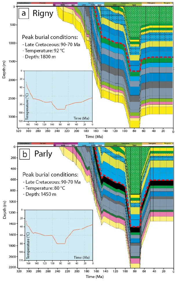
The two cores exhibit a different thermal and burial history (Fig. 2). Currently, the studied interval is 224
buried at a depth of 1537-1574 m in the basin depocenter (Rigny) and at a depth of 640-663 m on the 225
basin southern margin (Parly). The 3D model further predicts that at peak burial conditions the Middle 226
Jurassic carbonates experienced depths of 1800 m and 1450 m and temperatures of 92 and 80 °C in 227
the Rigny and Parly cores, respectively (Fig. 2). Figure 2 also illustrates that the carbonates experienced 228
a simple burial history characterized by a nearly continuous burial until Late Cretaceous, followed by 229
a main uplift event. Thus, the rocks mainly underwent normal overburden pressure (inducing 230
development of BPS) and escaped major tectonic deformations. 231
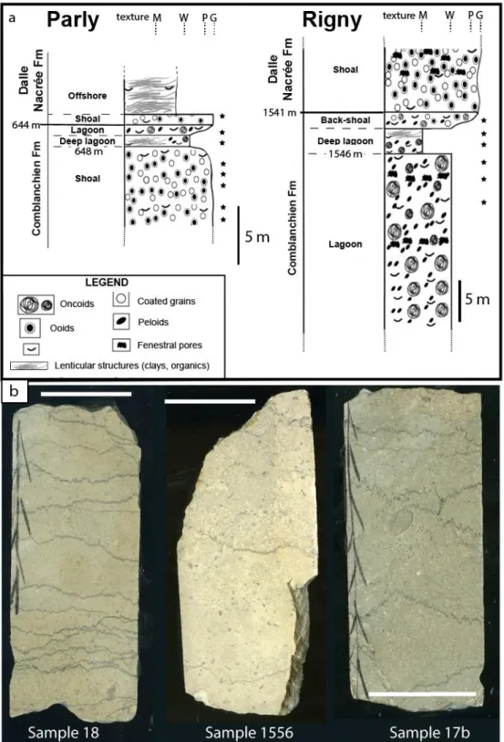
The Upper Bathonian – Lower Callovian stratigraphic interval investigated is 37 and 23 m thick in the 232
Rigny and Parly cores, respectively. Sedimentary logging and macro-facies analysis were accomplished 233
at the 1:100 scale and sampling for thin section preparation and petrographic micro-facies analysis 234
was performed on average every 1 m of core and specifically in close vicinity of the BPS selected for 235
SRIT analysis (Fig. 3a). Gas and water porosimetry on this stratigraphic interval at basin scale revealed 236
a wide range of porosities from 0 to 22%, with average and mode values that are 5.5% and 3-4%, 237
respectively (Delmas et al., 2010). However, 2D point counting estimates on thin sections from the 238
studied cores point towards porosity mostly below 5% (Mangenot et al., 2018). 239
Macro- and micro-facies analyses and comparison with previously published works (Gaumet, 1994, 240
1997; Granier, 1995; Gaumet et al., 1996) allowed us to distinguish a total of 23 carbonate facies from 241
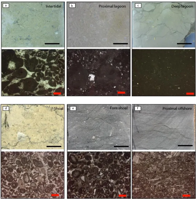
the two studied cores. Based on sedimentary structures, depositional textures, as well as type and 242
proportion of allochems, mud and primary pores, the 23 facies were ascribed to 6 depositional 243
environments (Fig. 4): (1) Intertidal deposits are mainly composed of packstone and grainstone 244
dominated by intraclasts (1-10 mm) and reworked oncoids (0.5-1.5 cm) with oblique lamination and 245
fenestral pores, typical of high energy sediments subjected to periodic emersions; (2) Sub-tidal lagoon 246
deposits are mainly composed by wackstone to packstone dominated by oncoids, locally reaching 2 247
cm in diameter (floatstone), and peloids, associated with planar microbial mats, suggesting a low to 248
medium energy environment; (3) Deep lagoon deposits are mainly composed of mudstone and 249
wackstone containing small (<1 mm) oncoids, locally associated with lenses of organic-rich sediments, 250
indicating a very low energy environment; (4) Back-shoal to shoal deposits. The former are mainly 251
composed of the lagoonal facies containing spill-over deposits derived from the shoal. The latter 252
include high energy grainstone and packstone composed of ooids (<2mm), coated grains (1-2 mm), 253
peloids (<0.5 mm), bioclast fragments (crinoids, corals, bryozoans, brachiopods, bivalves) locally with 254
cross-stratification and rare evidences of emersion associated with geopetal features and fenestral 255
pores; (5) Fore-shoal deposits include mud-, wack-, pack- and grainstone with dominant peloids (<0.5 256
mm) and bioclast fragments (mainly crinoids, brachiopods and bivalves) and encrusting serpulids; (6) 257
Off-shore deposits include wackstone with wavy bedding containing few crinoid fragments (<0.5 mm), 258
commonly recrystallized and locally associated with dark lenses of clay-size particles (organics or 259
siliciclastics), deposited in a low energy setting. 260
Petrographic analysis did not identify phyllosilicates like micas in any of the 23 sedimentary facies. 261
Minor clay-size particles, likely siliciclastic, were identified only in the off-shore environment and are 262
possibly linked to upwelling from distal plains, whereas clay-size particles, likely organic, were 263
identified in the deep lagoon environment where anoxic conditions could have favoured their 264
preservation. 265
For the scope of this survey the 23 facies identified were gathered into 4 main groups based on the 266
dominant carbonate textures (sensu Dunham, 1962) irrespective of the depositional environment of 267
provenance: (1) Mudstone to wackstone (locally with clay-size siliciclastic and organic particles) with 268
minor oncoids, peloids and bioclast fragments (<0.5 mm); (2) Wackstone to floatstone mainly with 269
oncoids, peloids and locally intraclasts (<2 mm); (3) Floatstone to packstone with oncoids, intraclasts 270
and locally peloids (1.5 cm); (4) Packstone to grainstone with ooids, coated grains, intraclasts, bioclasts 271
(mainly brachiopods and crinoids) and locally oncoids (up to 2 cm). These groups will be further used 272
to assess the role of the carbonate depositional texture on the results of SRIT analysis. 273
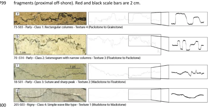
c. Stylolite populations 274
Stylolite populations in the cores consist exclusively of bedding-parallel stylolites (BPS) that formed in 275
response to vertical stress during burial (Fig. 3b), in a setting where the horizontal stress is likely to 276
remain isotropic. All peaks are observed normal to the stylolite planes, indicating that the governing 277
stress direction was vertical (Koehn et al., 2012), and that no horizontal displacement occurred along 278
the stylolite plane. The investigated core samples were typically 15-20 cm long (Fig. 3b). Twenty-five 279
(25) samples (core slabs) containing single-trace stylolites were considered for the SRIT, and forty-280
eight (48) stylolites were selected with lengths ranging from 1.5 cm to 7.4 cm. Sampling covers 281
different depositional facies and corresponding environments in both cores (Fig. 3a), comprising 14 282
samples (32 stylolites) from the Parly core (covering the 643-663 m depth interval) and 11 samples 283
(16 stylolites) from the Rigny core (covering the 1542-1559 m depth interval), respectively. Stylolites 284
were characterized regarding their morphologies, following the classification proposed by Koehn et 285
al. (2016). This classification comprises 4 classes of stylolites based on the shape of the roughness, 286
which itself is related to the stylolite growth (Fig. 5). In the following description the stylolite 287
morphology is split into a baseline corresponding to above-mm scale morphology and peaks referring 288
to below-mm scale morphology. Class 1 stylolites (rectangular layer) consist of a large rectangular 289
baseline with small peaks on the rectangle flat top. Class 2 stylolites (seismogram) are characterized 290
on the large scale by the occurrence of narrow top-hat like rectangles, with small-scale peaks. Class 3 291
(suture and sharp peak) includes all stylolites that have a flat or wavy base line with locally tall peaks. 292
Finally, Class 4 stylolites (simple wave) display a wavy base line and sparse small peaks. Numerous 293
core samples comprise stylolites with various morphologies, indicating that the morphology is 294
independent from the depositional textures/facies and corresponding environments. A rough 295
minimum estimate of the vertical displacement (compaction) that the studied stylolites 296
accommodated can be obtained by measuring the maximum amplitude of the teeth along the 2D 297
profile (Koehn et al., 2016, Toussaint et al., 2018). These amplitude values are reported in the Table 298
1, showing stylolites accommodated a minimum of 1.14 mm to 8.4 mm vertical displacement. 299
Superposition of stylolite teeth also suggests a complex polyphase development of pressure-solution 300
in the strata, and the anastomosed pattern results from complex interactions between stylolite planes 301
that likely destroyed the original roughness (Sinha-Roy, 2002; Laronne Ben-Itzhak et al., 2014). 302
Consequently, we discarded overprinted or fused stylolites from our study so that SRIT analysis 303
focussed on single, isolated stylolites only. 304
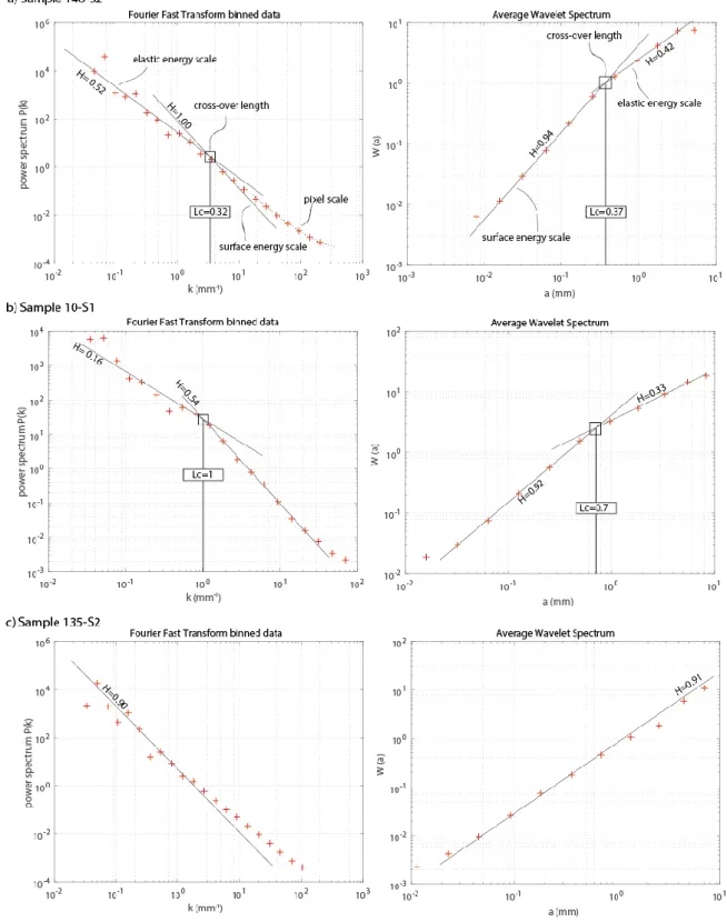
4. SRIT results 305
The roughness of forty-eight (48) stylolites was studied using both the FPS and AWC methods (Table 306
1). Figure 6 shows representative examples of the obtained treatment. By calculating the values of the 307
Hurst coefficient for each stylolite, we can divide the population into three categories: (1) stylolites of 308
which both small-scale and large-scale Hurst coefficients correspond to 1±0.1 and to 0.5±0.1, 309
respectively. These values are the theoretical ones expected from the growth model (Schmitbuhll et 310
al., 2004), and we consider an uncertainty of ±0.1 to account for user-related sources of error (stylolite 311
drawing and value reading mainly, Fig. 6a). Thirty-five and twenty-six stylolites satisfy this criterion 312
when analysed using AWC and FPS, respectively; (2) stylolites of which either one or both small-scale 313
and large-scale Hurst coefficients do not correspond to the theoretical values (Fig. 6b). Eight and 314
thirteen stylolites belong to this category, when analysed using AWC and FPS respectively; (3) stylolites 315
where roughness analysis does not show two growth regimes, hence no cross-over length (Fig. 6c). 316
Five and eight stylolites belong to this category, when analysed using AWC and FPS, respectively. The 317
fact that both small-scale and large-scale Hurst coefficients reconstructed satisfy the theory is the key 318
factor to select the stylolites among the population that are the best suited to be used as 319
paleopiezometers. This characteristic is hereafter referred to as the consistency. 320
In order to characterize the stylolites that are the best suited to be used for SRIT, we studied the 321
statistical distribution of the population considering the consistency with the growth model, the 322
stylolite morphology and the host rock texture. Vertical stress and corresponding burial depth 323
distribution modes (first and third quartiles and median) of the population were compared to the 324
depth predicted by the burial-thermal modelling. This approach enables us to establish the most 325
efficient way to use SRIT to access the maximum depth experienced by the strata on one hand, and to 326
assess the impact of the stylolite morphology or of the host rock texture on the other hand. It is worth 327
noting that the results from SRIT analysis are more consistent with the modelled depths when 328
analyzed using the AWC method rather than the FPS method. 329
To account for the difference in the depth estimates depending on the signal analysis method used, 330
we considered FPS and AWC averaged depth values for the stylolites that are referred to as consistent, 331
i.e. those with Hurst coefficients consistent with Schmittbuhl et al. (2004). More than 80% of the 332
stylolites satisfy the consistency criterion in our sample population, considering either results from 333
AWS, or from FPS or from both, the latter case encompassing 50% of the whole population. The depth 334
median value obtained from the average between FPS and AWC inversion for these stylolites is very 335
close to the maximum burial depth predicted by the burial-thermal model (Figs. 2 and 7). Indeed, SRIT 336
returns maximum depths of 1300 ± 100 m for the Parly core and 1650 ± 100 m from the Rigny core, 337
while maximum depths estimated by the basin model are 1450 m in Parly and 1800 m in Rigny. This 338
shows that the depth median value derived from a stylolite population can be used to reliably access 339
the maximum burial depth, provided stylolites satisfy the consistency criterion previously defined in 340
this study. 341
5. Discussion 342
a. Impact of the stylolite morphology on SRIT reliability 343
Sedimentary rocks host stylolites of various morphologies, which can be described based on teeth 344
frequency, wavelength and amplitude at different observation scales (Andrews and Railsback, 1997). 345
Stylolite morphology affects estimates of the chemical compaction and the efficiency of fluid flow 346
along the dissolution planes (Braithwaite, 1988; Meredith et al., 2011; Heap et al., 2013; Koehn et al., 347
2016). Morphology is likely to be controlled by both the growth regime (Koehn et al., 2016) and the 348
host rock heterogeneity distribution such as porosity (Andrews and Railsback, 1997) or pinning 349
particles (Koehn et al., 2007; 2012). Both these parameters deeply affect the ability of a stylolite to 350
record two-scales of growth regimes, hence reliable stress magnitudes (Renard, 2004; Ebner et al., 351
2009b; Ebner et al., 2010a; Ebner et al., 2010b; Rolland et al., 2014). The case study of the Middle 352
Jurassic carbonates from the Paris basin subsurface enables us to discuss how reliable the SRIT is with 353
respect to the stylolite morphology. We studied stylolites clearly related to the vertical stress applied, 354
with teeth oriented vertical and perpendicular to the dissolution plane, and formed in rocks containing 355
very few clays and no micas. In order to assess whether morphology plays a noticeable role on the 356
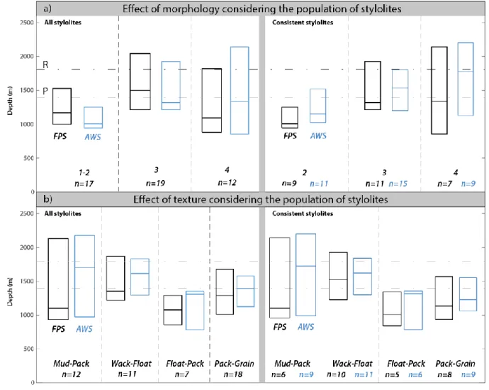
SRIT results, we reported a statistical analysis of the BPS populations as box-and-whisker plots as a 357
function of the morphology (Fig. 8a). It is worth noting that provided that the stylolite 2D profile is 358
long enough for both the roughness Hurst exponents to be found (>1.5 cm, Table 1), our dataset shows 359
that SRIT returns a Lc independent from the stylolite length and from the amount of vertical 360
displacement it accommodated. Also no correlation can be found between 2D profile length and the 361
validation of the consistency criterion. 362
SRIT results vary depending on the stylolite morphology (classes 2, 3 and 4, Fig. 8a): stylolites from 363
class 2 are systematically underestimating the maximum burial depth, with median values ranging 364
between 1000 and 1150 m, and up to 65% of the population satisfying the consistency criterion. 365
Stylolites from class 3 return a depth in line with the estimated maximum burial depth (1350 m – 1600 366
m) and up to 80% of the population is consistent with the depths derived from burial-thermal model 367
(Fig. 2). Stylolites from class 4 show the most scattered distribution, with no systematic behaviour 368
regarding the depth, suggesting they are not the best suited to obtain a reliable depth estimate, 369
despite 75% of them satisfying the consistency criterion. Stylolites belonging to class 3 seem to be the 370
best suited to calculate the maximum burial depth, while class 2 stylolites are better indicators of 371
intermediate depths. We suggest avoiding the simple wave-like stylolites (class 4), which will not 372
return a reliable depth, probably because of the lack of teeth, most of the signal then relying in a small-373
scale roughness which is difficult to digitize and so to analyse. 374
b. Impact of the host rock depositional texture on SRIT reliability 375
The texture of the host also seems to affect the inversion results (Fig. 8b), with consistent results for 376
the 4 textures documented. Texture 1 (mudstone to wackstone) returns the most scattered depth 377
distribution, with 75% consistency, and a clear difference in the median value for FPS (1100m) or for 378
AWC (1700m). Texture 2 (wackstone to floatstone) hosts stylolites that return a narrow depth 379
distribution (1400 to 1650m) in the range of the depths expected from the burial-thermal model 380
considering both cores, and 100% consistency. Textures 3 (floatstone to packstone) and 4 (packstone 381
to grainstone) host stylolites of which quartile distribution is narrow (1000 to 1400 m), with median 382
values slightly underestimating the maximum burial depth modelled with a consistency of 90% for 383
texture 3 and of 50% for texture 4. From this statistical representation, it returns that wackstone, 384
floatstone and packstone are the better suited host rock textures to assess the maximum burial depth, 385
grainstone hosting more than half of the inconsistent stylolites, and mudstone being the less suited 386
texture to assess a burial depth, should it be maximum or intermediate. 387
c. Limitations of SRIT and application beyond the case of sedimentary basins 388
The application of SRIT requires a good estimate of mechanical parameters (young modulus and 389
poison ratio) and of the solid-fluid interfacial energy. If the latter is strictly related to the host lithology 390
and does not vary much with the conditions of deformation (compaction, temperature, pressure), 391
mechanical parameters are likely to evolve as the host undergoes shortening or compaction, as 392
emphasized in Rolland et al. (2012). The Young’s modulus E is the most critical parameter to assess, 393
and determining it at the time of the deformation is not trivial. One solution was proposed by Ebner 394
et al. (2009b), that uses the SRIT results carried on several BPS hosted in the same rock to assess the 395
value of E prevailing at the time stylolites formed. The method inverts equation (2), using the 396
difference in vertical stress from BPS separated by a measured distance to access E. In cases where 397
the studied succession is not long enough to apply this approach (i.e. <10 m), a minimum requirement 398
to carry out SRIT is to know the value of E from mechanical tests (e.g. this paper). It is important to be 399
aware of these limitations when assessing vertical stress in deep conditions of deformation, or in 400
different lithologies. In addition, the SRIT presented in this paper is tied to the assumption that the 401
stress in the plane of the stylolite is isotropic. It is very likely that the horizontal stress remained 402
isotropic in settings with very limited shortening or extension like the subsidence phase of the Paris 403
Basin, however in other settings where SRIT was successfully applied such as foreland basins this 404
isotropy may not be valid (Beaudoin et al., 2016; Bertotti et al., 2017; Beaudoin and Lacombe, 2018). 405
In such settings, it appears important to check that the horizontal stress remained isotropic for a given 406
BPS, (1) by ensuring the teeth are perpendicular to the dissolution plane (so that the surface contains 407
no shear component) and (2) testing a sample with SRIT applied to a stylolite in three cuts at 60 408
degrees to each other that should return identical values for Lc, as anisotropy in stress creates an 409
anisotropy of the Lc values (Ebner et al., 2010b). Otherwise, alternative approaches exist for 410
anisotropic stresses along the stylolite plane, which typically occurs for tectonic stylolites (Ebner et al., 411
2010b; Beaudoin et al., 2016). 412
Formational fluids involved in the pressure-solution process have a strong impact on stylolite 413
development (Toussaint et al., 2018, and reference therein). In order to test the impact of fluids onto 414
SRIT, we consider the paleo-fluids circulating within the Middle Jurassic reservoirs of the Paris basin, 415
assessed on several cores from the basin depocenter and margin (including Rigny core, Mangenot et 416
al., 2017, 2018; Dassié et al., 2018). The studied interval in the Rigny core consists in a highly saline-417
dominated fluid system during the whole burial time (Cretaceous), yet various vertical stresses were 418
reconstructed by applying SRIT on this interval. Consequently, it suggests that the pore fluid chemistry 419
is not affecting the SRIT results. Also, the study of both Parly and Rigny cores illustrates that the 420
occurrence of oil migration at maximum burial, observed in Rigny but absent from Parly, does not 421
impact the SRIT result in spite of being able to affect stylolite development. This highlights that the 422
external parameters such as fluid chemistry or environment temperature affect stylolite development 423
(reviewed in Toussaint et al., 2018) but are not involved in SRIT equations and do not affect the SRIT 424
results. 425
d. Lessons learnt on sedimentary stylolite development 426
The study from the Middle Jurassic carbonates of the Paris basin highlights that 80% of the stylolite 427
population is consistent with the growth model, hence that they are suitable for SRIT. 20% of the 428
population of stylolites fails to return consistent Hurst coefficients with both methods. This failure 429
takes two shapes: (1) a single growth regime, always related to the surface energy scale, in which case 430
it is safe to assume that the 2D portion is too small to encompass where the Lc sits, emphasizing that 431
the 2D stylolite used for SRIT must be longer than the Lc by at least two orders of magnitude, or (2) 2 432
growth regimes, but the Hurst exponent being different from what the model predicts. In that case, 433
the roughness may have been altered during chemical compaction either by excessive pinning, an 434
effect that is especially visible in morphology classes 1 and 2 (Koehn et al., 2007; Ebner et al., 2009a), 435
or by a transient stop in the dissolution history, altering the roughness and Hurst exponent of the 436
large-scale elastic energy (Laronne Ben-Itzhak et al., 2014). 437
Half of the stylolites that show consistency with the growth model stopped developing at an 438
intermediate depth, returning an intermediate vertical stress value. The results of SRIT suggest two 439
possible scenarios to account for the development of stylolites that do not finish their growth at the 440
same depth: (1) all stylolites start dissolution at the same time, some stopping before others. (2) 441
stylolites start dissolution in sequence, class 2 forming and stopping, then class 3 forming and 442
stopping. The depth distribution shown in Figure 8a seems to support the latter case. However, such 443
a scenario requires that there is enough space in between dissolving stylolites to localize new ones. 444
As the dissolution increases during burial, the spacing between stylolites tends to decrease, because 445
of the physical effect of dissolution on the one hand, and because of the effect of increasing vertical 446
stress coupled to an increase in local fluid pressure (Kelka et al., 2017) due to a decrease in local 447
permeability around the stylolite (Koehn et al., 2016). Thus, it is physically unlikely that sedimentary 448
stylolites developed in sequence (class 2 then 3) and it is more sound to consider that all dissolution 449
planes start at the same time, with some stylolites stopping before others. 450
Our study shows that the seismogram pinning type morphology (class 2) statistically yields a fossil 451
stress signal that corresponds to an intermediate burial depth (Fig 9). Alternatively, the suture and 452
sharp peak type morphology (class 3), where pinning is distributed along the plane, tends to record 453
the maximum burial depth-related stress, suggesting that growth and so dissolution were active until 454
the maximum burial depth was reached (Fig. 9). This suggests that the strong localized pinning can kill 455
the roughness ability to record deep stress. The role of pinning may govern the impact of host texture 456
on SRIT results, i.e. that coarser grained texture returns intermediate values of vertical stress (Fig. 8). 457
Indeed, if we do not expect that heterogeneous grain size distribution in a sample would affect SRIT, 458
the range of grain sizes in a homogeneous sample will control the distribution of the pinning particles 459
(e.g. oxydes). In a rock with coarser grains like a grainstone, pinning particles will be further apart from 460
each other, and so the pinning will be localized in those points, leading to a shorter lifespan of the 461
stylolite. This idea corroborates the observations of Andrews and Railsback (1997), that reported that 462
more serrate stylolites (class 1 and 2 here) seem to predate less serrate stylolites (class 3). Authors 463
related this to the development of stylolites in sequence, affected by the evolution of the rock 464
lithology with burial, where destruction of porosity and decrease in amount of heterogeneities tends 465
to decrease the pinning effect. We propose that this observation rather reflects that most BPS initiated 466
at the same time, with the more serrate stylolites stopping their development earlier then the less 467
serrate stylolites because of the localized pinning, itself controlled by the distribution of pinning 468
particles in the rock (Koehn et al., 2012). Our study also reports that the minimum burial depth 469
recorded by a BPS at the time it stopped developing is 800 m, which suggests that dissolution started 470
at lower depth. That supports the studies reporting sedimentary stylolites developing at very shallow 471
depth (150m, e.g. Rolland et al., 2012), and contradicts the previous attempts to infer a minimum 472
burial depth needed for stylolite formation (from 800 m to 1000 m, Finkel and Wilkinson, 1990; 473
Railsback, 1993; Dunnington, 1967; Nicolaides and Wallace, 1997). Our study results suggest that a 474
combination of SRIT applied on classes 2 and 3 stylolites in carbonate rocks, considering each 475
stratigraphic unit as hosting a population, can be used to reconstruct a major part of the basin 476 subsidence history. 477 478 6. Conclusions 479
Using two cores from Middle Jurassic carbonate reservoirs of the Paris basin (France), of which the 480
burial-thermal history is well constrained, this contribution presents a first statistical appraisal of the 481
Stylolite Roughness Inversion Technique (SRIT) applied to sedimentary, bedding-parallel stylolites 482
(BPS) aiming to access maximum paleo-depth experienced by their host rocks. By direct comparison 483
between inversion results and modelled maximum burial depths, we define a mathematical 484
consistency criterion, fulfilled if stylolite roughness analysed with either the Fourier Power Spectrum 485
(FPS) or the Average Wavelet Coefficient (AWC) methods returns 2 growth regimes with Hurst 486
coefficient of 1±0.1 for the surface energy (typically encountered at a scale below 1 mm) and 0.5±0.1 487
for the elastic energy (above 1 mm). Then, the median values of the depth considering the stylolites 488
consistent with the growth model approach the maximum burial depths giving 1300m ± 130 m for the 489
southern margin core and 1650m ± 160m for the depocenter core. These values are close to (within 490
10%) those independently deduced from a thermally calibrated basin model, yielding maximum paleo-491
depths for the studied carbonates of 1450 and 1800 m, respectively. 492
From a distribution analysis, we assess the impact of stylolite morphology and host rock depositional 493
texture on the reliability of SRIT, and we propose that suture and sharp peak stylolite types are the 494
best suited to access the maximum paleo-depth, while the seismogram pinning type provides 495
intermediate depth values. This survey encourages future basin studies to use SRIT since a moderate 496
number of stylolites (<5) is needed to consistently return the maximum burial depth, or an 497
intermediate burial depth, provided that a selection of the stylolites based on their morphology is 498
properly made and that the Hurst coefficient consistency is respected. In cases where such selection 499
proves to be hard, we suggest that future studies should avoid using the simple wave-like stylolites 500
and the mudstone host rock textures, since both show the largest variability on SRIT results. We also 501
suggest to work on a population of a minimum of 15 stylolites to obtain a reliable estimate of the 502
maximum depth. 503
Beyond presenting a workflow to assess the maximum burial depth from BPS population, our study 504
points out that nearly 100% of the sedimentary, bedding-parallel stylolites developed in accordance 505
to the stress-driven growth theory that links the stylolite roughening to the applied stress. 80% of the 506
studied population retain this relationship intact. We propose that BPS development starts from the 507
same depth (≤ 800 m), with localized strong pinning tending to stop the dissolution at intermediate 508
depths during burial. Thus only the stylolites where pinning is distributed along the plane can yield the 509
maximum vertical stress magnitude. 510
Acknowledgements 511
The authors would like to thank R. Wells and R. Toussaint for their constructive reviews. The 512
subsurface cores of Rigny-la-Nonneuse and Parly were available from the IFPEN storage collection of 513
the BEPH (Bureau Exploration-Production d’Hydrocarbures). Fabrice Gaumet (Terramelior) is thanked 514
for valuable advice during sedimentary logging of the cores. 515
516
References 517
Aharonov, E., and Katsman, R., 2009, Interaction between pressure solution and clays in stylolite 518
development: Insights from modeling: American Journal of Science, v. 309, p. 607-632, 519
http://doi.org/10.2475/07.2009.04. 520
Alvarez, W., Engelder, T. and Geiser, P.A., 1978, Classification of solution cleavage in pelagic 521
limestones: Geology, v. 6, p. 263-266. 522
Andrade Ramos, J.R.D., 2000, Stylolites: Measurement of Rock Loss: Revista Brasileira de 523
Geosciências, v. 30, p. 4. 524
Andre, G., Hibsch, C., Fourcade, S., Cathelineau, M. and Buschaert, S., 2010, Chronology of fracture 525
sealing under a meteoric fluid environment: Microtectonic and isotopic evidence of major 526
Cainozoic events in the eastern Paris Basin (France): Tectonophysics, v. 490, p. 214-228. 527
Andrews, L. M., and Railsback, L. B., 1997, Controls on stylolite development: morphologic, 528
lithologic, and temporal evidence from bedding-parallel and transverse stylolites from the 529
US Appalachians: The Journal of Geology, v. 105, no. 1, p. 59-73. 530
Angheluta, L., Mathiesen, J. and Aharonov, E., 2012., Compaction of porous rock by dissolution on 531
discrete stylolites: a one-dimensional model: Journal of Geophysical Research, v. 117, p. 8, 532
http://doi.org/10.1029/. 533
Averbuch, O., and Piromallo, C., 2012, Is there a remnant Variscan subducted slab in the mantle 534
beneath the Paris basin? Implications for the late Variscan lithospheric delamination process 535
and the Paris basin formation: Tectonophysics, v. 558, p. 70-83. 536
Barabási, A.-L., and Stanley, H.E., 1995, Fractal concepts in surface growth: Cambridge university 537
press, 366 p. 538
Barbarand, J., Quesnel, F., and Pagel, M., 2013, Lower Paleogene denudation of Upper Cretaceous 539
cover of the Morvan Massif and southeastern Paris Basin (France) revealed by AFT 540
thermochronology and constrained by stratigraphy and paleosurfaces: Tectonophysics, v. 541
608, p. 1310-1327. 542
Baron, M., and Parnell, J., 2007, Relationships between stylolites and cementation in sandstone 543
reservoirs: Examples from the North Sea, U.K. and East Greenland: Sedimentary Geology, v. 544
194, p. 17-35, http://doi.org/10.1016/j.sedgeo.2006.04.007. 545
Bathurst, R.G., 1987, Diagenetically enhanced bedding in argillaceous platform limestones: stratified 546
cementation and selective compaction: Sedimentology, v. 34, p. 749-778. 547
Bathurst, R.G., 1991. Pressure-dissolution and limestone bedding: the influence of stratified 548
cementation, in Einsele, G., Ricken, W., and Seilacher, A., eds., Cycles and Events in 549
Stratigraphy: Springer [Berlin], p. 450–463. 550
Baud, P., Rolland, A., Heap, M., Xu, T., Nicolé, M., Ferrand, T., Reuschlé, T., Toussaint, R., and Conil, 551
N., 2016, Impact of stylolites on the mechanical strength of limestone: Tectonophysics, v. 690, 552
p. 4-20, http://doi.org/10.1016/j.tecto.2016.03.004. 553
Beaudoin, N., and Lacombe, O., 2019, Recent and future trends in paleopiezometry in the diagenetic 554
domain: Insights into the tectonic paleostress and burial depth history of fold-and thrust belts 555
and sedimentary basins: Journal of Structural Geology, 556
https://doi.org/10.1016/j.jsg.2018.04.001 (in press). 557
Beaudoin, N., Koehn, D., Lacombe, O., Lecouty, A., Billi, A., Aharonov, E., and Parlangeau, C., 2016, 558
Fingerprinting stress: Stylolite and calcite twinning paleopiezometry revealing the complexity 559
of progressive stress patterns during folding-The case of the Monte Nero anticline in the 560
Apennines, Italy: Tectonics, v. 35, p. 1687-1712, http://doi.org/10.1002/2016tc004128. 561
Bemer, E., and Lombard, J. M., 2010, From injectivity to integrity studies of CO2 geological storage-562
chemical alteration effects on carbonates petrophysical and geomechanical properties: Oil & 563
Gas Science and Technology–Revue de l’Institut Français du Pétrole, v. 65, no 3, 445-459. 564
Benedicto, A., and Schultz, R.A., 2010, Stylolites in limestone: Magnitude of contractional strain 565
accommodated and scaling relationships: Journal of Structural Geology, v. 32, p. 1250-1256, 566
http://doi.org/10.1016/j.jsg.2009.04.020. 567
Bertotti, G., de Graaf, S., Bisdom, K., Oskam, B., Vonhof, H.B., Bezerra, F.H., Reijmer, J.J., and Cazarin, 568
C.L., 2017. Fracturing and fluid-flow during post-rift subsidence in carbonates of the Jandaíra 569
Formation, Potiguar Basin, NE Brazil: Basin Research, v. 29, p. 836-853. 570
Bjorkum, P.A., 1996, How important is pressure in causing dissolution of quartz in sandstones?: 571
Journal of Sedimentary Research, v. 66, p. 147-154. 572
Braithwaite, C.J.R., 1988, Stylolites as open fluid conduits: Marine and Petroleum Geology, v. 6, p. 93-573
96. 574
Brouste, A., Renard, F., Gratier, J.-P., and Schmittbuhl, J., 2007, Variety of stylolites' morphologies and 575
statistical characterization of the amount of heterogeneities in the rock: Journal of Structural 576
Geology, v. 29, p. 422-434, http://doi.org/10.1016/j.jsg.2006.09.014. 577
Brunet, M.F., and Le Pichon, X., 1982, Subsidence of the Paris basin: Journal of Geophysical Research: 578
Solid Earth, v. 87, p. 8547-8560. 579
Bruna, P.O., Lavenu, A.P., Matonti, C. and Bertotti, G., 2018, Are stylolites fluid-flow efficient 580
features?: Journal of Structural Geology, https://doi.org/10.1016/j.jsg.2018.05.018 (in press) 581
Candela, T., Renard, F., Bouchon, M., Brouste, A., Marsan, D., Schmittbuhl, J, and Voisin, C., 2009, 582
Characterization of Fault roughness at various scales : implication of three dimensional high 583
resolution topography measurements. In: Ben-Zion, Y., and Sammis, C., (eds.): Mechanics, 584
Structurre and Evolution of Fault Zones, Birkhauser Basel, p. 1817-1851. 585
Croizé, D., Renard, F., Bjørlykke, K., and Dysthe, D.K., 2010, Experimental calcite dissolution under 586
stress: Evolution of grain contact microstructure during pressure solution creep: Journal of 587
Geophysical Research: Solid Earth, v. 115, B09207, http://doi.org/10.1029/2010jb000869. 588
Dassié, E.P., Genty, D., Noret, A., Mangenot, X., Massault, M., Lebas, N., Duhamel, M., Bonifacie, M., 589
Gasparrini, M., Minster, B., and Michelot, J.-L., 2018, A newly designed analytical line to 590
examine fluid inclusion isotopic compositions in a variety of carbonate samples: 591
Geochemistry, Geophysics, Geosystems, v. 19,p. 1107–1122. 592
http://doi.org/10.1002/2017GC007289 593
Delmas, J., Houel, P., and Vially, R., 2002, Paris Basin, Petroleum potential: IFP regional Report. 594
Delmas, J., Brosse, E., and Houel, P., 2010, Petrophysical properties of the middle jurassic carbonates 595
in the PICOREF Sector (South Champagne, Paris Basin, France): Oil and Gas Science and 596
Technology–Revue de l’Institut Français du Pétrole, v. 65, p. 405-434. 597
Dunham, R.J., 1962, Classification of carbonate rocks according to depositional textures, in: Ham, 598
W.E., ed., Classification of Carbonate Rocks, AAPG [Tulsa], p. 108 – 121. 599
Dunnington, H.V., 1967, Aspects of Diagenesis and Shape Change in Stylolitic Limestone Reservoirs: 600
World Petroleum Congr. Proc., Mexico, vol. 2, pp. 339–352. 601
Ebner, M., Koehn, D., Toussaint, R., and Renard, F., 2009a, The influence of rock heterogeneity on the 602
scaling properties of simulated and natural stylolites: Journal of Structural Geology, v. 31, p. 603
72-82, http://doi.org/10.1016/j.jsg.2008.10.004. 604
Ebner, M., Koehn, D., Toussaint, R., Renard, F., and Schmittbuhl, J., 2009b, Stress sensitivity of stylolite 605
morphology: Earth and Planetary Science Letters, v. 277, p. 394-398, 606
http://doi.org/10.1016/j.epsl.2008.11.001. 607
Ebner, M., Piazolo, S., Renard, F., and Koehn, D., 2010a, Stylolite interfaces and surrounding matrix 608
material: Nature and role of heterogeneities in roughness and microstructural development: 609
Journal of Structural Geology, v. 32, p. 1070-1084, http://doi.org/10.1016/j.jsg.2010.06.014. 610
Ebner, M., Toussaint, R., Schmittbuhl, J., Koehn, D., and Bons, P., 2010b, Anisotropic scaling of 611
tectonic stylolites: A fossilized signature of the stress field?: Journal of Geophysical Research, 612
v. 115, B06403, http://doi.org/10.1029/2009jb006649. 613
Ehrenberg, S., 2006. Porosity destruction in carbonate platforms: Journal of Petroleum Geology, v. 614
29, p. 41-52. 615
Ehrenberg, S.N., Eberli, G.P., Keramati, M., and Moallemi, S.A., 2006, Porosity-permeability 616
relationships in interlayered limestone-dolostone reservoirs: AAPG Bulletin, v. 90, p. 91-114, 617
http://doi.org/10.1306/08100505087. 618
Espitalié, J., Maxwell, J., Chenet, Y., and Marquis, F., 1988, Aspects of hydrocarbon migration in the 619
Mesozoic in the Paris Basin as deduced from an organic geochemical survey: Organic 620
Geochemistry, v. 13, p. 467-481. 621
Finkel, E.A., Wilkinson, B.H., 1990, Stylolitization as a source of cement in Mississippian Salem 622
limestone, West-Central Indiana: AAPG Bull, v. 74, p. 174–186. 623
Fletcher, R.C., and Pollard, D.D., 1981, Anticrack model for pressure solution surfaces: Geology, v. 9, 624
p. 419-424, http://doi.org/10.1130/0091-7613(1981)9<419:amfpss>2.0.co;2. 625
Garcia, J.-P., 1993, Les variations du niveau marin sur le bassin de Paris au Bathonien-Callovien. 626
Impacts sur les communautés benthiques et sur l'évolution des Ornithellidés 627
(Terebratellinida). Mémoires Géologiques de l'Université de Dijon, 310 p. 628
Garcia, J.-P., and Sambet, 1994, Macrobenthic associations as a biostratigraphical tool for high 629
resolution correlations within mixed siliciclastic/carbonates sequences (Middle Jurassic, Paris 630
Basin). Book of abstracts "High resolution sequence stratigraphy: innovations and 631
applications", Liverpool - p. 283-287. 632
Gaumet, F., 1994, Stratigraphie séquentielle haute resolution en milieu carbonaté: l´exemple de la 633
plate-forme Bourguignonne au Bathonien et au Callovien [Ms Thesis] : Université de Dijon, 50 p. 634
Gaumet, F., 1997, Fondements géologiques pour la modélisation stratigraphique des systèmes 635
carbonatés: le jurassique moyen de l'Angleterre à la Méditerranée [PhD Thesis] : Université 636
C. Bernard – Lyon, 290 p. 637
Gaumet, F., Garcia, J.-P., Dromart, G., and Sambet, G., 1996, Contrôle stratigraphique des faciès, 638
géométries et profils de dépôt de la plate-forme carbonatée bourguignonne au Bathonien-639
Callovien : Bulletin de la Société géologique de France, v. 167, p. 409-421. 640
Granier, B., 1995, A sedimentological model of the Callovian oolite reservoir of the Villeperdue oil 641
field, Paris Basin (France): TOTAL Exploration Production, Scientific and Technical Center, p. 642
145-150. 643
Gratier, J.P., Muquet, L., Hassani, R., and Renard, F., 2005, Experimental microstylolites in quartz and 644
modeled application to natural stylolitic structures: Journal of Structural Geology, v. 27, p. 645
89-100, http://doi.org/10.1016/j.jsg.2004.05.007. 646
Guillocheau, F., Robin, C., Allemand, P., Bourquin, S., Brault, N., Dromart, G., Friedenberg, R., Garcia, 647
J.-P., Gaulier, J.M., Gaumet, F., Grosdoy, B., Hanot, F., Le Strat, P. et al. 2000. Meso-Cenozoic 648
geodynamic evolution of the Paris Basin: 3D stratigraphic constraints. Geodinamica Acta, 13, 649
189-245. 650
Guillocheau, F. 1991. Mise en évidence de grands cycles transgression-régression d'origine tectonique 651
dans les sédiments mésozoiqies du Bassin de Paris. C.R. Académie des Sciences de Paris, 312, 652
1687-1593. 653
Hassan, H.M. 2007. Stylolite effect on geochemistry, porosity and permeability: Comparison between 654
a limestone and a dolomite sample from Khuff-B reservoir in Eastern Saudi Arabia. The 655
Arabian Journal of Science and Engineering, 32, 10. 656
Heap, M.J., Baud, P., Reuschle, T. and Meredith, P.G. 2013. Stylolites in limestones: Barriers to fluid 657
flow? Geology, 42, 51-54, http://doi.org/10.1130/g34900.1. 658
Homewood, P., Guillocheau, F., Eschard, R., and Cross, T, 1992, Corrélation haute resolution et 659
stratigraphie génétique: une demarche intégrée : Bull. Centres Rech. Explor. – Prod. Elf-660
Aquitaine, Boussens, v. 16, p. 357-381. 661
Karcz, Z. and Scholz, C.H. 2003. The fractal geometry of some stylolites from the Calcare Massiccio 662
Formation, Italy. Journal of Structural Geology, 25, 1301-1316, 663
http://doi.org/10.1016/s0191-8141(02)00173-6. 664
Kelka, U., Veveakis, M., Koehn, D. and Beaudoin, N. 2017. Zebra rocks: compaction waves create ore 665
deposits: Scientific reports, 7, 14260. 666
Khair, H.A., Cooke, D. and Hand, M. 2013. The effect of present day in situ stresses and paleo-stresses 667
on locating sweet spots in unconventional reservoirs, a case study from Moomba-Big Lake 668
fields, Cooper Basin, South Australia. Journal of Petroleum Exploration and Production 669
Technology, 3, 207-221. 670
Khair, H.A., Cooke, D. and Hand, M. 2015. Seismic mapping and geomechanical analyses of faults 671
within deep hot granites, a workflow for enhanced geothermal system projects. Geothermics, 672
53, 46-56. 673
Koehn, D., Renard, F., Toussaint, R. and Passchier, C. 2007. Growth of stylolite teeth patterns 674
depending on normal stress and finite compaction. Earth and Planetary Science Letters, 257, 675
582-595, http://doi.org/10.1016/j.epsl.2007.03.015. 676
Koehn, D., Ebner, M., Renard, F., Toussaint, R. and Passchier, C.W. 2012. Modelling of stylolite 677
geometries and stress scaling. Earth and Planetary Science Letters, 341-344, 104-113, 678
http://doi.org/10.1016/j.epsl.2012.04.046. 679
Koehn, D., Rood, M.P., Beaudoin, N., Chung, P., Bons, P.D. and Gomez-Rivas, E. 2016. A new stylolite 680
classification scheme to estimate compaction and local permeability variations. Sedimentary 681
Geology, 346, 60-71, http://doi.org/10.1016/j.sedgeo.2016.10.007. 682
Koepnick, R. 1987. Distribution and permeability of stylolite-bearing horizons within a Lower 683
Cretaceous carbonate reservoir in the Middle East. SPE Formation Evaluation, 2, 137-142. 684
Lacombe, O., Laurent, P. and Angelier, J. 1994. Calcite twins as a key to paleostresses in sedimentary 685
basins: Preliminary results from drill cores of the Paris basin. Peri-Tethyan Platforms, F. Roure 686
Ed.: Technip, 197-210. 687
Lacombe, O., Angelier, J., Byrne, D. and Dupin, J. 1993. Eocene‐Oligocene tectonics and kinematics of 688
the Rhine‐Saone Continental Transform Zone (eastern France). Tectonics, 12, 874-888. 689
Lacombe, O., Angelier, J., Laurent, P., Bergerat, F. and Tourneret, C. 1990. Joint analyses of calcite 690
twins and fault slips as a key for deciphering polyphase tectonics: Burgundy as a case study. 691
Tectonophysics, 182, 279-300. 692
Laronne Ben-Itzhak, L., Aharonov, E., Karcz, Z., Kaduri, M. and Toussaint, R. 2014. Sedimentary 693
stylolite networks and connectivity in limestone: Large-scale field observations and 694
implications for structure evolution. Journal of Structural Geology, 63, 106-123, 695
http://doi.org/10.1016/j.jsg.2014.02.010. 696
Le Solleuz, A., Doin, M.-P., Robin, C. and Guillocheau, F. 2004. From a mountain belt collapse to a 697
sedimentary basin development: 2-D thermal model based on inversion of stratigraphic data 698
in the Paris Basin. Tectonophysics, 386, 1-27. 699
Mangenot, X., Gasparrini, M., Rouchon, V. and Bonifacie, M. 2018. Basin‐scale thermal and fluid flow 700
histories revealed by carbonate clumped isotopes (Δ47)–Middle Jurassic carbonates of the
701
Paris Basin depocentre. Sedimentology, 65, 123-150. 702
Mangenot, X., Bonifacie, M., Gasparrini, M., Götz, A., Ader M., Rouchon, V., 2017. Coupling Δ47 and
703
fluid inclusion thermometry on carbonate cements to precisely reconstruct the temperature, 704
salinity and 18O of paleo-groundwater in sedimentary basins. Chemical Geology, 472: 44-57.
705
DOI: 10.1016/j.chemgeo.2017.10.011 706
Mangenot, X., Gasparrini, M., Bonifacie, M., Gerdes, A. and Rouchon, V. 2017. An emerging thermo-707
chronometer to resolve longstanding enigmas in sedimentary basin analysis - Δ47/(U-Pb).
708
Goldschmidt, Paris. 709
Martín-Martín, J., Gomez-Rivas, E., Gómez-Gras, D., Travé, A., Ameneiro, R., Koehn, D. and Bons, P. 710
2018. Activation of stylolites as conduits for overpressured fluid flow in dolomitized platform 711
carbonates. Geological Society, London, Special Publications, 459, 157-176. 712
Meredith, P.G., Baud, P., Heap, M.J., Rolland, A. and Toussaint, R. 2011. Influence of compaction 713
bands and stylolites on the permeability of porous rocks. Flows and mechanics in natural 714
porous media from pore to field scale. Pore2Field, Reuil-Malmaison, 4. 715
Merino, E., Ortoleva, P. and Strickholm, P. 1983. Generation of evenly-spaced pressure-solution 716
seams during (late) diagenesis: A kinetic theory. Contributions to Mineralogy and Petrology, 717
82, 360-370. 718