A DUAL-MESH STRATEGY FOR THE 3D SIMULATION OF
FINEBLANKING PROCESSES
N. Manopulo
1*, L. Tong
1, C. Karadogan
1, P. Hora
11
Institute of Virtual Manufacturing
Swiss Federal Institute of Technology, Zurich
ABSTRACT: Fineblanking technology is used to produce blanked metal components which show outstanding surface
quality and part flatness. The defining characteristics of the process are, besides the use of a counter punch and a V-Ring, the tiny die clearance and a rounded cutting edge. The 3D FE simulation of the process proves to be thus very challenging. This is mainly because in comparison to the part dimensions (which are of the order of 10mm) a very small mesh size needs to be chosen on the cutting edge (~0.01mm), which leads to a very big number of elements and also tiny time steps. This paper aims to show a solution to the problem using the Arbitrary Lagrangian Eulerian FE formulation, applied on two different levels of refinement. First a relatively coarse mesh (element size of about 0.1mm around the cutting edge) is applied to solve the full size 3D problem. The flow information is subsequently used on a much finer mesh (size ~0.005) defined around a small region on the cutting line to accurately compute the stress-strain distribution around the radii.
KEYWORDS: Fineblanking, ALE, FEM, Multi-scale
1 INTRODUCTION
Fineblanking, as its name suggests, is a special category of blanking [1]. Its main differences with respect to simple blanking are the use of a V-Ring and a counter punch, in order to keep an advantageous compressive stress state in the cutting region. Furthermore a very small die clearance (about 0.5% of the blank thickness) and similarly small punch radii are distinctive characteristics of the process. Fine blanked products show thus superior surface quality and part flatness as compared to simple blanked components.
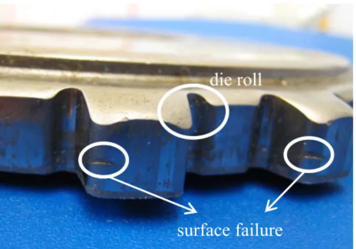
Commonly encountered problems in fine blanking are the presence of a die roll and surface failures (see Figure 1).
____________________
* Corresponding author: Technoparkstrasse 1 CH-8005 Zürich, +41 44 633 7807, +41 44 633 1596, manopulo@ivp.mavt.ethz.ch
The former is disadvantageous as more material has to be used in order to provide the necessary active material surface, whereas the latter is a serious surface defect which can be unacceptable in applications where high surface quality is necessary. These problems are usually minimized with an iterative optimization process during the production and tryout of the fineblanking tools. Simulating the process would help reducing the optimization effort in hardware in a substantial manner. The numerical simulation of the fineblanking process has been therefore investigated in various occasions. In 2001 Klocke et al. gave an overview of the possibilities offered by FEM for fineblanking applications [2]. At the same year Hambli et. al. suggested a 2D FE Model in ABAQUS to investigate the process [3].Later on Chen et al. proposed a mixed u/p FEM-Formulation to solve the 2D problem [4]. Kwak et al., in turn, investigated influence of the die clearance [5]and of the V- the Ring [6] using the DEFORM2D code. Chan et al. published a new 2D rezoning algorithm for the fineblanking simulation [7].
2 MOTIVATION
As it can be seen in the previous section, literature on finblanking simulation is mainly based on 2D FE codes. The main reason for this has been the fact that the geometrical parameters defining the problem show very strong differences in scale. A typical fine blanked product has dimensions (including blanking depth) in the
die roll
surface failure
Figure 1: Die roll and surface failure
DOI 10.1007/s12289-009-0495-8 © Springer/ESAFORM 2009
order of 10mm. However radii on the blanking punch and the die clearance go down to the order of 0.01mm. Thus if a full-scale 3D simulation needs to be carried out, the enormous number of elements and the tiny time step quickly lead to prohibitive computational costs. Although 2D simulations are very useful in order to get an insight about the main effects under various process parameters, they fall short of solving many industrial problems. This is because many of the fineblanked products clearly present features that require a 3D simulation. This can be better understood looking to figure 1. The differences in die roll on the fineblanked gear hint to the fact that the material flow varies along the cutting line substantially, thus the need for the 3rd
dimension. A solution strategy will be delineated in the following which uses the intrinsic characteristics of the process in order to reduce the computational effort of a 3D simulation to acceptable levels.
3 SOLUTION APPROACH
An analysis of the problem will be presented in the following. A description of the numerical tools and models used in order to overcome the challenges described in the previous section will be given together with short theoretical hints.
3.1 ALE FORMULATION
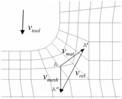
The first challenge to face arises from the nature of blanking operations. The strongly localized and large deformations, typical for these processes, have to be accurately computed. The Updated Lagrange FE formulation with tetrahedral elements, used in many commercial packages, presents here serious disadvantages. As nodes are updated according to the material velocities, elements get quickly distorted, leading to extremely short time steps and costly remeshing operations. The ALE approach, allows updating the FE mesh independently from the material velocity field [8]. Figure 2 shows the velocity field and the mesh velocity at a point near the cutting punch.
In a classical Updated Lagrange approach node A would have to move to A’. A more convenient mesh would however result, if node A were moved in the direction of the tool velocity to A”. However this corresponds no longer to the material point in A as the latter moved in
the direction of the material flow. The value of any state variable φ defined in A’ can be transformed to its value in A” by taking into account the convective effect.
φ
A"=
φ
A'−
∇
φ
⋅
(
v
mat−
v
mesh)
(1) In case of rigid-plastic material description the only history variable is the equivalent strain, which can be described according to the following relationship [8].Δ
+Δ=
Δ
+Δ−
∇
⋅
(
v
mat−
v
mesh)
(2) eq t t Lag eq t t ALE eqε
ε
ε
, ,A wise choice for the mesh velocity in the vicinity of the tool contact region is
v
mesh=
v
tool (3) The nodes on the surface however should be updated in a purely Lagrangian manner in order to accurately follow the domain boundary.
v
mesh=
v
maton
∂
Ω
(4) More information about the method can be obtained in [8],[9] and [10].3.2 COARSE MESH SOLUTION
Although the ALE formulation helps increasing time steps, the intrinsic difference in the order of magnitude of the geometric features in the problem still leads to prohibitive computational costs. If however the radii around the cutting edge are neglected, the domain can be discretised with much less elements and much bigger time steps.
Figure 3: Comparison of a coarse simulation with the
real counterpart
Figure 3 shows the simulation results obtained with a coarse mesh in comparison to the corresponding real product. It can be seen that the formation of the die roll is accurately simulated, hinting to the fact that the
low is correctly computed. Furthermore the simulated tool forces show good agreement with theoretical results.
overall material f
3.3 COUPLED FINE MESH SOLUTION
With a coarse mesh however, no information can be obtained about the material flow around the cutting edge
A mat
v
toolv
relv
meshv
A’ A”Figure 2:ALE description 590
Unblanked Zone Right blanked
zone
Left blanked zone
radii, which is absolutely necessary for the prediction of surface failure.
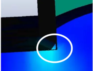
Figure 4 shows a close zoom of the punch (radius = 0.05mm) at the beginning of the blanking process. Clearly the resolution selected for the workpiece is not sufficient to represent the flow around the tool radius. The results of the coarse computation can instead be used to isolate small sections on the cutting line, which can be recomputed including the cutting radii with a much finer resolution.
As it is depicted in Figure 5, the x-y components of the velocity field are transferred from the coarse mesh to the fine mesh by interpolation. The upper and lower boundary conditions are once again defined through the movement of the tools as well as the free surface.
Figure 6 shows the maximum principal stress development in a coupled fine mesh computation, where a punch radius of 0.05mm and a die radius of 0.25 have been used. To note is that the tensile stress maxima occur as expected on the surface of the blanked material around the smaller radius.
4 IMPLEMENTATION
In this section we will discuss the way the solution has been implemented into our fineblanking code FINEFORM. Both the coarse and the fine levels have been solved using the ALE method. We will hint for both levels to the way the FE mesh is generated, updated and if necessary regenerated. The z-axis is defined as the blanking direction, whereas the x-y plane represents the blank surface.
Figure 4: Insufficient resolution of the coarse level
4.1 COARSE SIMULATION WITH ALE 4.1.1 Mesh generation
First a 2D mesh is generated such that the cutting line falls in the middle of three element layers. The rest of the geometry can be meshed arbitrarily. The 2D mesh is then expanded to the blanking direction to form the hexahedral mesh. In order to successfully implement an ALE solution, the movement of the mesh needs to be defined independently from the material flow. This is best done by assigning different node groups and defining the behaviour of each group separately. Figure 7 shows our implementation of the grouping in the x-y plane. The black directed line represents the cutting line.
Figure 7: Coarse mesh generation
4.1.2 Mesh update (ALE)
As it can be followed on Figure 8, at each increment the left and right blanked zones are moved with the velocity of the tools with which they are in contact and the nodes are redistributed in the z direction. The unblanked zone instead gets narrower and its nodes are also redistributed. Finally the surface nodes are updated according to the material velocity field (pure Lagrangian nodes).
Cutting Line
Figure 8: Coarse mesh update
Figure 6: Coupled fine mesh simulation
Left Group
Right Group
Figure 5: Coupling of coarse and fine solutions
5 CONCLUSIONS
5 CONCLUSIONS
4.1.3 Remeshing
The mesh update strategy described above causes the nodes in the unblanked zone to come close to each other, while the nodes in the left and right blanked zones tend to increase their distance. After a while this results in low quality elements and the domain has to be rezoned. The remeshing is carried out by deleting a layer of elements from the unblanked zone and adding a layer of elements to each of the upper and lower blanked zones.
A new method for the 3D simulation of fineblanking processes has been proposed. It can be said that the use of an ALE formulation proves to be particularly adequate for fineblanking processes. This is because the latter show a narrow deformation band around the cutline with dominant deformation in the blanking direction. This allows a simple mesh update and remeshing strategy. Furthermore using again the z-dominance of the process, effects in the xy plane are transferred to a finer local mesh, reducing computational cost and without significant loss in accuracy. The experimental validation of the methodology and quantitative results will be the subject of a future publication.
A new method for the 3D simulation of fineblanking processes has been proposed. It can be said that the use of an ALE formulation proves to be particularly adequate for fineblanking processes. This is because the latter show a narrow deformation band around the cutline with dominant deformation in the blanking direction. This allows a simple mesh update and remeshing strategy. Furthermore using again the z-dominance of the process, effects in the xy plane are transferred to a finer local mesh, reducing computational cost and without significant loss in accuracy. The experimental validation of the methodology and quantitative results will be the subject of a future publication.
4.2 COUPLED FINE SIMULATION WITH ALE 4.2.1 Mesh generation neration
The fine mesh is first parametrically generated in 2D based on the geometry parameters:
The fine mesh is first parametrically generated in 2D based on the geometry parameters:
• Punch radius • Punch radius • Die radius
• Die radius
• Die clearance
• Die clearance
REFERENCES
REFERENCES
• Blanking height
• Blanking height [1] Schmidt R.-A.: Umformen und Feinschneiden. Carl Hanser Verlag München Wien, 2007.
[1] Schmidt R.-A.: Umformen und Feinschneiden. Carl Hanser Verlag München Wien, 2007.
• Upper, lower, left and right limits • Upper, lower, left and right limits
An example of the parametric mesh can be seen in Figure 9.
An example of the parametric mesh can be seen in
Figure 9. [2] Klocke F., Sweeney K., Raedt H.-W.: Improved tool design for fine blanking through the application of numerical modelling techniques, Journal of
Materials Processing Technology, 115:70-75, 2001. [2] Klocke F., Sweeney K., Raedt H.-W.: Improved tool
design for fine blanking through the application of numerical modelling techniques, Journal of
Materials Processing Technology, 115:70-75, 2001.
The so generated plane mesh is then expanded along the cutting line to generate the hexahedral mesh.
The so generated plane mesh is then expanded along the cutting line to generate the hexahedral mesh.
4.2.2 Mesh update (ALE) 4.2.2 Mesh update (ALE)
The mesh update strategy is quite similar to the coarse case. With the difference that now there are two node bands corresponding to the two cutting corners that move directly with the tool velocity. The nodes in the unblanked and blanked regions are again redistributed in each increment. The redistribution however is not equidistant but biased such that small elements will be generated close to the corners and larger elements getting farther away. The Lagrangian update of the surface is optional. If nodes are updated, the domain follows the coarse mesh surface. Otherwise the fine mesh remains inside the coarse mesh and boundary velocities are also applied to the upper and lower surfaces.
The mesh update strategy is quite similar to the coarse case. With the difference that now there are two node bands corresponding to the two cutting corners that move directly with the tool velocity. The nodes in the unblanked and blanked regions are again redistributed in each increment. The redistribution however is not equidistant but biased such that small elements will be generated close to the corners and larger elements getting farther away. The Lagrangian update of the surface is optional. If nodes are updated, the domain follows the coarse mesh surface. Otherwise the fine mesh remains inside the coarse mesh and boundary velocities are also applied to the upper and lower surfaces.
4.2.3 Remeshing 4.2.3 Remeshing
The remeshing is exactly carried out as in the coarse case. Layers in the unblanked zone are deleted and new layers in the blanked zones are added, as need arises. The remeshing is exactly carried out as in the coarse case. Layers in the unblanked zone are deleted and new layers in the blanked zones are added, as need arises.
[3] Hambli R.: Finite element simulation of fine blanking processes using a pressure dependent damage model, Journal of Materials Processing Technology, 116:252-264, 2001.
[3] Hambli R.: Finite element simulation of fine blanking processes using a pressure dependent damage model, Journal of Materials Processing Technology, 116:252-264, 2001.
[4] Chen Z.H., Tang C.Y., Lee T.C., Chan L.C.: Numerical simulation of fine-blanking process using a mixed finite element method, International Journal of Mechanical Sciences, 44:1309-1333, 2002. [4] Chen Z.H., Tang C.Y., Lee T.C., Chan L.C.:
Numerical simulation of fine-blanking process using a mixed finite element method, International Journal of Mechanical Sciences, 44:1309-1333, 2002. [5] Kwak T.S., Kim Y.C., Bae W.B.: Finite element
analysis on the effect of die clearance on shear planes in fine blanking, Journal of Materials Processing Technology, 130-131:462-468, 2002. [5] Kwak T.S., Kim Y.C., Bae W.B.: Finite element
analysis on the effect of die clearance on shear planes in fine blanking, Journal of Materials Processing Technology, 130-131:462-468, 2002. [6] Kwak T.S., Kim Y.C., Seo M.K., Bae W.B.: The effect of V-ring indenter on the sheared surface in fine-blanking process of pawl, Journal of Materials Processing Technology, 143-144:656-661, 2003. [6] Kwak T.S., Kim Y.C., Seo M.K., Bae W.B.: The effect of V-ring indenter on the sheared surface in fine-blanking process of pawl, Journal of Materials Processing Technology, 143-144:656-661, 2003. [7] Chan L.C., Leung Y.C., Lee T.C. Fan J.P., Tang
C.Y.: Numerical simulation of fine-blanking – a new approach, Materials Science and Engineering A364:207-215, 2004.
[7] Chan L.C., Leung Y.C., Lee T.C. Fan J.P., Tang C.Y.: Numerical simulation of fine-blanking – a new approach, Materials Science and Engineering A364:207-215, 2004.
[8] Tong L.: FE Simulation of bulk forming processes with a mixed Eulerian-Lagrangian formulation, Diss. ETH No 11107, 1995.
[8] Tong L.: FE Simulation of bulk forming processes with a mixed Eulerian-Lagrangian formulation, Diss. ETH No 11107, 1995.
[9] Tong L., Hora P., Reissner J.: Application of the arbitrary Lagrangian Eulerian method in the FE-simulation of 3-D bulk forming processes, Numiform 92, Chenot J.-L., Wood R. D. and Zienkiewicz O. C. (eds.) pp. 669-674, 1992. [9] Tong L., Hora P., Reissner J.: Application of the
arbitrary Lagrangian Eulerian method in the FE-simulation of 3-D bulk forming processes, Numiform 92, Chenot J.-L., Wood R. D. and Zienkiewicz O. C. (eds.) pp. 669-674, 1992. [10] Huetnik J.: On the simulationof thermo mechanical
forming processes, a mixed Eulerian-Lagrangian finite element method, Diss. University of Twente, Enschede, 1986.
[10] Huetnik J.: On the simulationof thermo mechanical forming processes, a mixed Eulerian-Lagrangian finite element method, Diss. University of Twente, Enschede, 1986.
Figure 9: Fine mesh generation
![Figure 9. [2] Klocke F., Sweeney K., Raedt H.-W.: Improved tool](https://thumb-eu.123doks.com/thumbv2/123doknet/14869008.638874/4.892.85.429.492.701/figure-klocke-f-sweeney-k-raedt-improved-tool.webp)
