The following is a reprint from Perat Orthop Traumatol 2004:16:89–116 and continues the
new series of articles at providing continuing education on operative techniques to the
European trauma community.
Posterior Stabilization of the Cervical
and Upper Thoracic Spine with the CerviFix®
Bernard Jeanneret, Stefan Schären
1Ab stract
Objective: Posterior stabilization of the occipitocervical junction, the upper and lower cervical spine (C-spine), and the upper thoracic spine (T-spine) using the Cervi-Fix® rod system, a modular tension band system made of titanium. Various connectors are attached to the pli-able rod. 3.5-mm screws are inserted through the con-nectors into the occiput and into each motion segment of C- and T-spine in an optimal position.
Indications: Occipitocervical and upper C-spine insta-bilities (malformations, tumors, infections, aseptic in-flammatory lesions, posttraumatic conditions). Instabilities of the lower C-spine on the condition that the anterior column is intact (iatrogenic, posttraumatic instabilities caused by degenerative or inflammatory processes, tumors). Degenerative or posttraumatic painful conditions of the lower C-spine. Additional pos-terior stabilization after anpos-terior spondylodesis of the C-spine or upper T-spine.
Contraindications: Absent stability of the anterior column due to vertebral body destruction caused by trauma, infection, or tumors.
Surgical Technique: Insertion of screws into the oc-ciput and/or into the lateral masses or pedicles of the C-spine or upper T-spine depending on the level to be fused. Adaptation of rods and their attachments to the screws with the help of connectors. Addition of autog-enous cancellous bone grafts.
Results: The CerviFix® system was used for various pathologic conditions in 54 patients (26 women, 19 men, average age 59 years). Average duration of
fol-low-up of 47 patients was 20 months. Bony fusion was obtained in all. We did not see any implant-associated complications.
Key Words
Cervical spine · Posterior fusion · Internal fixation · Cervical instability
Eur J Trau ma 2004;30:334–49
DOI 10.1007/s00068-004-1096-3
Surgical Principles and Objective
The titanium CerciFix® rod system is used for surgical
stabilization of the occipitocervical junction, the upper and lower cervical spine (C-spine), and the upper tho-racic spine (T-spine) affected by various pathologic con-ditions. It allows to adapt the positioning of screws to the individual anatomy, and their positioning does not depend on the rod. The rather small size of the implant always permits generous apposition of cancellous bone to ensure uneventful fusion.
Advantages
• Optimal placement of every screw needed for anchor-age of the system.
• The system allows stabilization from the occiput to the upper T-spine. In toddlers, stabilizations of the C-spine, the T-C-spine, and the lumbar spine (L-spine) are possible depending on the age.
1 Departement of Orthopedics, Kantonsspital Basel, Switzerland.
Reprint from Operat Orthop Traumatol 2004;16:89–116 DOI 10.1007/s00064-004-1096-9
• Possibility to cranially extend any rod system used at the T-spine with the CerviFix®.
• Lateral placement of the rod over the lateral masses of the C-spine leaving sufficient space for apposition of cancellous bone, even in the presence of extensive laminectomies.
• Postoperative magnetic resonance imaging (MRI) possible.
• Little soft tissue irritation given the small size of the implant.
Disadvantages
• The use of the CerviFix® as a tension band device is
only possible in the presence of an intact anterior col-umn able to resist compression. The intactness of the column can be either primary or after reconstruction of an anterior defect.
• Considerable cost of the system. Indications
• Occipitocervical and upper C-spine instabilities (mal-formations, tumors, infection, aseptic inflammatory processes, posttraumatic instabilities).
• Instabilities of the lower C-spine on the condition that the anterior column is intact (iatrogenic, posttraumatic, degenerative, inflammatory, or tumoral instabilities). • Degenerative or posttraumatic painful conditions of
the lower C-spine.
• Posterior stabilization after anterior spondylodesis of the C-spine or upper T-spine.
• Instabilities of the C-, T- and L-spine in toddlers. Contraindications
• Absent stability in compression of the anterior column such as after posttraumatic, infectious or tumoral de-struction of vertebral bodies.
Patient Information • Usual surgical risks.
• Risk of quadri- or paraparesis/-plegia after more ex-tensive interventions. This risk is small and cannot be quantified exactly.
• Risk of damage to nerve roots due to malpositioned or too long screws.
• Risk of pseudarthrosis and metal breakage, in particu-lar, if the recommended postoperative immobilization is not respected.
• Decreased range of motion of the C-spine. • Shaving of occipital region necessary.
• Extended and sometimes broad scar at the neck. • Need for orthesis to be worn postoperatively.
Preoperative Work Up • Neurologic assessment.
• Anteroposterior (AP) and lateral radiographs of C-spine and, if indicated, of T-C-spine. Bending and flex-ion/extension films. Computed tomography (CT) or MRI depending on the underlying condition.
• The patient should be brought into the operating room head first; this facilitates surgery and intraoperative image intensification. The anesthetist takes his place at the foot end of the table.
Surgical Instruments and Implants • Bipolar cautery.
• Bone wax.
• Self-retaining retractors, Langenbeck retractors, small Hohmann retractors.
• Aspirators, small and heavy gauge tubing.
• CerviFix® system (Stratec Medical, 4436 Oberdorf,
Switzerland), comprising two different rods as well as various connectors and hooks (Figures 1 and 2). • 3.5-mm screw set with long drill bits and taps. • Periosteal elevators (Cobb), small dissectors. • Rongeurs and Kerrisons, small and large.
• Set for bone graft harvesting including oscillating saw with large and narrow blades.
• Available: cerclage wire and bone cement. Anesthesia and Positioning
• Procedure in the presence of an unstable C-spine (os odontoideum, fractures): general anesthesia with en-doscopic nasotracheal intubation. A routine intubation may cause an unwarranted displacement of vertebrae. • Procedure in instances of a stable C-spine: standard
intubation.
Transfer from Bed/Stretcher to Operating Table • Procedure to follow for unstable C-spines: after
intu-bation, transfer of the patient en bloc to the operating table and prone positioning. The surgeon stabilizes the C-spine manually and makes sure that no change of the C-spine relative to the body occurs during trans-fer and positioning. After transtrans-fer, immediate image
• Procedure to follow for stable C-spines: details of the transfer are identical, an image intensifier control, however, is not necessary.
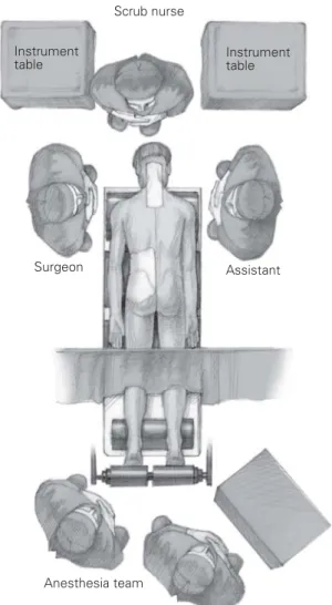
Positioning on the Operating Table (Figure 3)
• Prone, respecting the usual precautions for proper ventilation and avoidance of pressure points and ve-nous stasis of the lower body half. We use a modifica-tion of the Relton-Hall frame.
• Prevention of pressure points at the level of the patella through placement of cushions under the distal thigh, a soft roll is placed under the ankles.
• The patients are wearing TED stockings. • The head is positioned in a head cup. • Arms are placed along the body.
• For short fusions (two to three segments), the neck should be positioned in slight flexion as long as no risk exists for a recurrence of the reduced disloca-tion (image intensifier control). A flexion of the neck is not indicated in instances of more extensive fusions, particularly of occipitocervical fusions. The head must be positioned straight in neutral position to avoid any kyphosis during instrumentation and fixation. 1 2 5 4 3 1 2 5 4 3
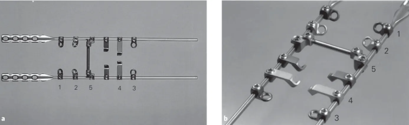
Figures 1a and 1b. Implants. a) Rods: two different rods are available, both have a diameter of 3.5 mm. One is a simple rod for use at the lower
C-spine and the T-C-spine. The other has been developed for the occipitocervical stabilization and, consequently, one end is fashioned resembling a 3.5-mm AO reconstruction plate [13]. The rods can be shortened to the desired length and adapted to fit the anatomic situation. b) Connectors: the various connectors permit all screw positions that are necessary for the upper and lower C-spine and the T-spine [2, 4–7, 9–11]. The direction of the screw in the connector is predetermined by the connector; it has, however, a 10° of freedom in all directions. This versatility can be augmented by a slight swiveling of the connector on the rod. If desired, locking screws of the anterior cervical locking plate (AO-CSLP) developed by Morscher et al. [12] can be used. This permits obtaining an angular stability between screw and implant.
1: a connector with a cranial inclination of 45° is available for the insertion of a transarticular screw C1/2 [5, 6, 10]. 2: a connector with a cranial inclination of 45° and a lateral inclination of 25° has been developed for insertion of screws into the lateral masses of the lower C-spine [11]. 3: another connector allowing an anterior screw direction is available. It has been designed for transpedicular screw fixation of the upper T-spine or for anchorage into C2. In addition, this connector can be used for screw anchorage into the transverse processes of the T-spine or for transpe-dicular screw fixation in the lower C-spine [9]. 4: connectors with lamina hooks are available in two sizes: they can be passed either cranial or caudal around the lamina. 5: connectors for transverse rods: these transverse stabilizers were designed for instances of extensive laminectomies. They not only increase the stability of the construct (relatively unimportant) but also protect the spinal cord. Moreover, they can be used to attach the neck muscles.
a b
Figure 2. Parallel connectors. They permit to connect any rod system
used in the T-spine with the CerviFix® implanted at the C-spine.
Technique of Screw Placement
Remarks concerning the technique of drilling: the risk of injuring brain, nerves, and vessels after exiting of the drill bit from the opposite cortical wall can be reduced considerably by using a special drilling technique (guard-ed drill technique). The wrist of the hand that holds the drill is grasped with the other hand. The forearm of this hand rests on the patient’s thorax or shoulder. This helps to control the pressure of drilling and to stop the pressure as soon as the resistance to drilling decreases. The drill bit is advanced only by 2–3 mm, drilling is then
stopped, the drill slightly withdrawn and again advanced until a bony contact is felt. Drilling is then resumed to a depth of 2–3 mm. This step is repeated until no bony contact can be felt or until a decrease in resistance is felt. The perforation of the opposite cortical wall can be confirmed with the depth gauge. If during the advance-ment of the drill bit a bony contact cannot be felt defini-tively, drilling should not be continued. In this instance, the drill canal should be explored with the dull end of a Kirschner wire or with a depth gauge.
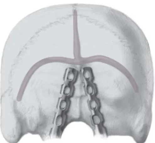
Figure 4. Screw insertion into the occiput. The thickness of the skull varies considerably. The thickest part of the occiput is found at its midline.
Already 2–3 cm more lateral it is much thinner. Therefore, the screws should be placed as close to the midline as possible and find purchase in the both laminae. The cranial end of the rods must be placed as close to the midline as possible, just below the external occipital protuberance; this allows the use of the longest screws possible. Inside the skull, the confluence of the venous sinuses lies at the level of the external occipital protuberance; consequently, bicortical screws should not be inserted into the protuberance itself.
During drilling care has to be taken not to injure the brain after perforation of the lamina interna. Therefore, the drilling technique described here is a must. An alternative procedure consists of the use of depth-adjustable drill sleeves allowing drilling to a predetermined depth. The depth of drilling is gradually increased and regularly measured with a depth gauge until the lamina interna has been perforated.
The dura may be injured in spite of a meticulous drilling technique, and cerebrospinal liquor may run through the drill hole. This is of no conse-quence, as the flow will stop as soon as the bicortical screw has been inserted. Temporarily, bone wax can be inserted into the drill hole.
Surgical Technique Figures 4 to 24
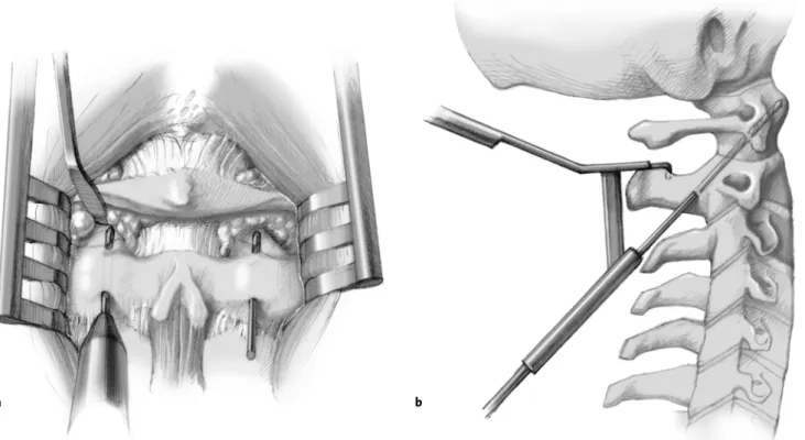
Figures 5a and 5b. Transarticular screw insertion C1/C2. The course of the vertebral artery must have been elucidated preoperatively by a CT given
the individual variations. Prior to drilling and screw insertion into C1/C2, the isthmus of C2 must be exposed subperiosteally on both sides (a). The screw’s entry point into C2 lies in a sagittal line behind the isthmus directly cranial to the articular process of C2. At this site, one often finds an anatomic depression that facilitates the start of drilling. The drill bit, as seen in the lateral imaging with the image intensifier, must be inclined in such a way as to point to the mid or upper part of the anterior arch of the atlas. The drill bit is advanced in a strictly sagittal direction under image intensifier control again employing the above described technique of drill bit advancement. The drill bit must pass close to the posterior cortex of the isthmus to avoid the vertebral artery lying anterior to it. Of help in obtaining the proper direction of drilling, a specially developed aiming device can be used (b) [1]. The drill bit is advanced through the atlantoaxial joint up to the anterior cortex of the atlas until it is perforated. The drill bit remains in place until the opposite side has been instrumented and C1/C2 stabilized. Tapping must reach beyond the atlantoaxial joint to avoid separation between atlas and axis during screw insertion.
b a
25°
25° 25°
Figure 6. Anchorage of screws in C2. On account of the particular anatomic conditions at C2, screw placement at this level is different from that at
C3–C7. For the anchorage of the screw in C2, the same screw direction as for the transarticular screw insertion can be used. However, the atlanto-axial joint is not crossed, the tip of the screw remaining subchondral.
Another possibility, shown here, consists of screw placement into the isthmus of C2. This necessitates a cranial and medial inclination of the drill bit by 25° in direction to the anteromedial border of the atlantoaxial joint. Tapping is limited to a depth of 1 cm. Also here, the tip of the screw lies subchondral.
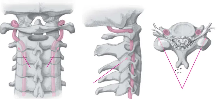
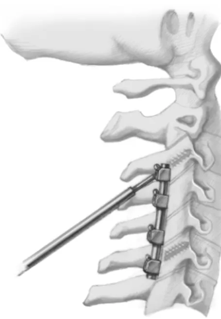
Figure 7. Anchorage of screws in C3–C7. The screws’ entry points lie 1–2 mm cranial and medial to the midpoint of the lateral masses. The drill holes
lie parallel to the surfaces of the facet joints; they diverge laterally by 25°. They perforate the anterolateral border of the masses of the articular processes cranially. The direction of the articular surfaces can the determined with a small dissector introduced into the joint. The length of the screws is measured with the depth gauge, and tapping is limited to a depth of 0.5 cm. Thanks to the marked divergence of the screws, the risk of injury to the vertebral artery is minimized. Nevertheless, great care must be taken during drilling. Should the drill bit be pushed through the anterior cortex of the articular process into the soft tissues, injury to a spinal nerve, small vessels, or, at least, the muscles is a distinct possibility.
25º
7−10° 7−10°
Figure 8. Transpedicular screw insertion at the T-spine. The entry points of the screws into the lateral masses are determined in the AP plane
un-der image intensifier control and marked with Kirschner wires. Once the entry points have been marked, drilling is done unun-der image intensifier control in the lateral plane using the guarded drill technique up to the mid part of the vertebral body. The depth gauge is used to explore the drill hole to ascertain that the spinal canal has not been opened. The depth gauge is also used to determine the screw’s length. Tapping is limited to a depth of 0.5 cm. Should difficulties arise during drilling, the screws may exceptionally be anchored in the transverse processes [3]. This, however, decreases the stability of anchorage in the upper T-spine; it will require a relatively longer external immobilization.
Scrub nurse Instrument
table Instrumenttable
Surgeon Assistant
Anesthesia team
Figure 9. Position of patient, surgeon, assistant,
scrub nurse as well as the anesthesia team during surgery.
Surgical Technique for Occipitocervical Fusion, e.g., C0/C4
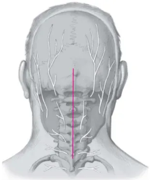
Figure 10. Midline skin incision from the external occipital protuberance to the
spinous process of C7. Subperiosteal exposure of occiput, the posterior arch of the atlas, the posterior elements of C2 as well as the spinous processes, posterior arch-es and articular procarch-essarch-es of C3 and C4 and partially of C5. For the transarticular screw placement C1/C2, the isthmus of C2 must also be exposed bilaterally.
C1 C2
C3 C4
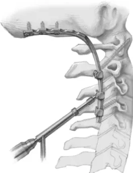
Figure 11. The trial rod is now exactly
adapt-ed to the occiput. Its cranial end must bor-der the midline immediately caudal to the external occipital protuberance. At the level of C2, C3 and C4, the rod must lie over the lateral edge of the articular processes. Normally, an angle of, at least, 90–100° ex-ists between occiput and C-spine. The trial rod must show a corresponding angula-tion. The rod is also used to determine the required length of the definite rod. The titanium rod with its plate-shaped end is cut to the appropriate length de-termined by the trial rod with a cutter. Depending on the anatomic situation, it may become necessary to shorten the plate by one hole. Bending irons are used to give the rod the appropriate shape. The angle of 90–100° must lie at the junction between rod and plate. Checking of the correct shape in situ.
Nota bene: repeated bending back and forth weakens the titanium rod and may cause its breakage.
Figure 12. An atlantoaxial dislocation, if present, is reduced under
image intensification. Drilling of both holes for the transarticular screws. The drill bit used to make the first hole is left in place during drilling of the second hole and instrumentation at this side. The drill bit temporarily left in place acts as a provisional C1/C2 stabilizer.
Figure 13. Now the screw hole is drilled in the most caudal vertebra
to be fused (in our example C4).
Figure 14. All connectors needed for the definitive fixation are
mounted on the rod and slightly fixed. The rod with the connectors is positioned, and the screw C1/C2 and the most caudal screw are inserted through the connector, but not tightened.
Figure 15. The plate-shaped end of the rod is brought to the midline
just below the external occipital protuberance, and the most cranial screw is inserted through the hole in the plate after appropriate drill-ing and tappdrill-ing. Thereafter, the two remaindrill-ing screws are inserted into the occiput.
Figure 16. The remaining connectors that lie between C2 and the most
cau-dal element (in our example C3) are brought into an optimal position. Drill holes into the bone are made through the connectors, the length of the screws is determined, the holes are tapped, and the screws inserted.
Figures 17a and 17b. Once the opposite side has been instrumented (a), a corticocancellous bone graft is harvested from the posterior iliac crest
(b). Notches are made at opposite ends for wedging between occiput and spinous process of C2. For better fitting, a small horizontal groove can be prepared with a burr in the occiput. In addition, the bone graft can be pressed against the spinal column with cerclage wires led around the
Figures 18a to 18d. a) This 67-year-old woman has been treated for several months on account of severe neck pain. A rapidly progressing
quadri-paresis appeared a few weeks before emergency admission; at this point, the patient was unable to walk. MRI showed a marked narrowing of the spinal canal at the level C1/C2 due to a pseudarthrosis of the dens of unknown etiology. The patient also had a posterior compression at the level C5/C6 (not well seen in this picture). b) Both atlantoaxial joints are destroyed. c) To decompress the spinal cord, the C1/C2 displacement was reduced, the foramen magnum enlarged, and a laminectomy C1 performed in addition to partial laminectomies of C2 and C5/C6. On account of the marked degenerative changes of the lower C-spine and the preexisting spontaneous fusion C3/4 and C5/6, a posterior stabilization C0–C6 was performed instead of a fusion C0–C2.
An impressive improvement of the cervical myelopathy occurred postoperatively; after a few days, the patient was able to walk with help. 12 months postoperatively, the patient had improved further, she could now walk with canes. The severe neck pain had disappeared.
d) Postoperative MRI of the C-spine shows a decompression of the spinal cord.
a b
c
Figure 19. The drill holes into the bone through the most cranial (in our example C3) and the
most caudal (C6) connector are prepared as described above. The articular process of C7 is often smaller than that of the other levels. Therefore, it is advisable to use a lamina hook for fixation in C7. Of course, a pedicle screw fixation can be used, if desired or necessary.
Figure 21. Finally, the intermediate connectors are brought into the desired position, the holes
are drilled through the connectors, the length of the screws is determined, the holes are tapped, and the screws inserted. The connectors must be able to slide along the rod during screw tight-ening. The locking bolts should only be tightened at the very end. Once both sides have been instrumented, the rotatory stability can be increased through the use of a transverse stabilizer. This protects the dura after extensive laminectomies. Cancellous bone is apposed anterior and medial to the rods. Closure of the wound in layers; the muscles can be attached to the trans-verse rods.
Nota bene: after a laminectomy, care has to be taken to solidly stabilize the cancellous bone
Figure 20. All connectors necessary for
instrumentation are mounted on the rod that is cut to proper length and bent to obtain a lordosis. They are provisionally fixed to the rod. The screws C3 and C6 are introduced through the connector but not tightened. If a slight posterior compres-sion (causing a lordosis) is desired, the cranial connector is slightly approximated to the caudal connector and fixed on the rod. The tightening of the cranial screw produces an intersegmental compres-sion and, thus, a lordosis. An exaggerated tightening and compression, however, may lead to screw avulsion.
a b
c d
a
b
Figures 22a to 22d. a) 50-year-old woman with spinal stenosis of the C-spine and progressive arm pain and sensibility disturbances of both hands
as well as severe neck pain. b) A laminectomy C3–6 with laminoplasty C4 was done to decompress the spinal cord. To alleviate the severe neck pain, a posterior fusion of the degeneratively changed segments C3–6 was done at the same time. c) Intraoperative photographs show the CerviFix® before and after apposition of cancellous bone. There is sufficient space anterior and medial to the implant for bone grafts. d) This postoperative MRI shows well the decompression of the spinal cord. In spite of the implants’ presence, the quality of imaging is good.
Figures 23a and 23b. a) 58-year-old man
suf-fering from ankylosing spondylitis. Unilat-eral fracture-dislocation C4/5, left side, fol-lowing fall in the bathroom. No neurologic deficit. b) Reduction of dislocation through a posterior approach and stabilization of the unstable injury. Given the long lever arms acting on the site of injury, an extended in-strumentation with two screws each crani-ally and caudcrani-ally was chosen. Postoperative immobilization in a Philadelphia collar for 3 months. At the last follow-up 36 months postoperatively, the patient was free of symptoms at the site of injury, no loosening or displacement of implants.
Figures 24a and 24b. a) 67-year-old man
with a left-sided paresis C7 and C8 of sud-den onset due to an acute Escherichia coli spondylodiscitis C7/T1. The MRI shows a huge epidural abscess. b) An anterior de-bridement was done on an urgent basis. During surgery, pus ran out from the in-tervertebral space precluding an anterior spondylodesis. 1 week later, an anterior spondylodesis C6/T1 and a posterior sta-bilization C6/T1 using the CerviFix® were done. The screws in C6 were inserted into masses of the articular processes and pedicle screws were used at T1. 1 year post-operatively, radiographs did not show any evidence of persisting infection, the fu-sion was solid.
Postoperative Management
Postoperative Care after Fusion of the C-Spine • A soft foam collar is worn over the dressing.
• Mobilization of patient on day 1 with a semirigid collar such as a Philadelphia collar.
• First dressing change on day 2. Immediate dressing change, if dressing is blood-soaked.
• Removal of stitches on day 12.
• Subsequent to the removal of stitches, the patient is allowed to remove the collar during the meals and for personal hygiene. Soft collar during nighttime.
• Isometric exercises of cervical and neck muscles as well as posture and respiratory exercises as soon as tolerated. The C-spine should always be actively ex-tended, continued resting of the chin on the collar must be avoided.
• Progressive weaning off from collar after 10 weeks. • First radiologic control after 3 months. At this time,
the spondylodesis should have almost consolidated. Thereafter, physical activities can be increased de-pending on symptoms.
• Normal physical activities after 4 months.
• In instances where bone cement was used instead of cancellous bone (only in the presence of metastases
Postoperative Care after Occipitocervical Fusion
• In principle, the care is identical to that outlined above. The immobilization must, however, be more rigid. Therefore, we use a four-post orthesis that rests on the chest such as the Repona frame. This orthesis must be worn for 3 months. During the night, how-ever, it can be exchanged for a Philadelphia collar. If the bone quality is rather poor putting the stability of fixation at risk, or if an extended fusion such as an oc-cipitothoracic fusion has been done, an immobiliza-tion in a Minerva cast may be advisable.
Errors, Hazards, Complications
• Arterial bleeding from a drill hole: if the screw hole into C2 is drilled improperly, injury of the vertebral artery may occur. Such a bleeding may be lethal. If the bleeding is profuse, the artery must be exposed im-mediately from posterior (this necessitates resection of the articular processes). The artery is either ligated or sutured using microsurgical technique. If this is not possible at the level of C2, the bleeding may be stopped by the insertion of the screw.
• Massive venous bleeding from a drill hole: in this in-Surgical Procedure at the Upper T-Spine
The surgical technique is identical to that at the lower C-spine with the exception of the use of pedicle screws instead of screws inserted into masses of the articular
processes. The use of lamina hooks is also possible at the T-spine. They can be placed around the lamina ei-ther from cranial or caudal.
• Cerebrospinal liquor flowing from the hole: sealing of the hole with the screw.
• Injury to a spinal nerve caused by a too long screw protruding anteriorly from the articular process: ex-change of screw.
• Injury to a spinal nerve caused by the drill bit or any other instrument: no treatment possible.
• Screw avulsion: tightening of screws, particularly of those inserted into the articular processes must be done with great care. If the connectors are already tightly fixed on the rod, strong compression or dis-traction forces may be generated during tightening, depending on whether the most cranial or the most caudal screw is tightened. If such forces are undesir-able, the connectors should be able to glide freely on the rod during screw tightening.
• Breakage of the rod: the rods are made of titanium. If they are repeatedly bent back and forth, they may break.
• Postoperative kyphosis at the craniocervical junc-tion: the angle between occiput and C-spine normally amounts to at least 90–100°. Therefore, during an oc-cipitocervical fusion the rod must be bent at the plate end by at least this amount. Otherwise, a kyphotic malposition of the head will result.
Results
Until now, we have implanted this system in 54 patients (26 women, 19 men, age 5–86 years, average age 59 years). Only one patient was younger than 25 years.
Indications were painful degenerative changes of the C-spine in 14 patients; extensive spinal stenosis in 14, three of which were caused by rheumatoid arthritis, all decompressions were achieved from posterior using a laminectomy; acute traumatic instability in five; meta-static destruction causing an instability in seven; C1/C2 instability secondary to rheumatoid arthritis in three; and C4/C5 spondylolisthesis due to rheumatoid arthritis in one. The system was used four times for additional stabilization after anterior debridement and interbody spondylodesis, three times for additional stabilization in the presence of other pathologies (one each for ky-phosis, fracture, and spinal stenosis). The CerviFix® was
employed twice for painful instabilities secondary to malformations. Finally, in a 5-year-old child, we used the CerviFix® to stabilize unilaterally a congenital
sco-liosis of the C-spine after excision of a wedge vertebra. Depending on the localization of the lesion, we per-formed twelve occipitocervical, 30 cervical, ten
cervico-thoracic, and two upper thoracic fusions. In 18 patients, we added to the stabilization a laminectomy at one or more levels.
In all patients but those with metastatic lesions, we added autologous bone harvested from the iliac crest. In the seven patients with metastatic destructions, we used bone cement.
The average duration of surgery amounted to 143 min (70–360 min), the average blood loss measured 610 ml (50–3,000 ml)
Intraoperative implant-related complications were never observed.
Complications
We observed five general postoperative complications. – A left-sided C5 paresis was seen in a 52-year-old
wom-an after wom-an extensive laminectomy that regressed only slowly during 1 year.
– A 74-year-old woman died suddenly on day 8 after a normal postoperative course. The only finding at au-topsy was a pneumonia.
– A 77-year-old man suffering from a metastasizing prostate carcinoma died 2 weeks postoperatively from a renal shutdown.
– A wound healing disturbance was seen in a 32-year-old schizophrenic patient with ankylosing spondylitis. It healed by secondary intention.
– A deep calf vein thrombophlebitis was observed in a paraplegic patient with a C5 burst fracture. Elsewhere, a corpectomy had been performed, and we added a pos-terior stabilization C3–8 on account of additional poste-rior injuries. The patient had been anticoagulated.
Follow-Up
We were able to follow up 47 patients over 3–67 months (average 20 months). The duration of follow-up was > 24 months in 23 patients, between 12 and 24 months in 13, and < 12 months in eleven.
Seven patients had died before the moment of fol-low-up.
– A 77-year-old man with a metastasizing prostate carci-noma died 2 weeks postoperatively due to acute renal shutdown.
– A 74-year-old woman died suddenly on day 8. Her postoperative course had been uneventful.
– A 73-year-old woman died 2 months postoperatively from cardiac failure.
– Four patients succumbed to their malignancies be-tween 2 and 7 months postoperatively.
Implant Removal
Implant removal was performed three times on account of symptoms. It was done twice after 10 and once after 24 months. All the fusions had healed.
Follow-up radiographs revealed once a screw break-age and once a loosening of a connector. In one of these patients, the anterior spondylodesis was solid, and in the other suffering from rheumatoid arthritis, an anterior fusion had occurred spontaneously. Therefore, as far as we can determine, all spondylodeses showed a bony bridging.
The implant system [8] described here has proven to be of value in the treatment of various pathologies in 54 patients. It allows a screw insertion independent of the implant, and it can be adapted to the given anatomic situations. As shown during bench testing and clinical outcomes, the system is sufficiently stable for a poste-rior instrumentation at the C-spine. We never observed an implant-related complication; bony fusion could be seen in all patients.
References
1. Gebhard JS, Schimmer RC, Jeanneret B. Safety and accuracy of transarticular screw fixation C1-C2 using an aiming device. Spine 1998;23:2185–9.
2. Grob D, Jeanneret B, Aebi M, et al. Atlanto-axial fusion with transarticular screw fixation. J Bone Joint Surg Br 1991;73:972–6. 3. Heller JG, Shuster JK, Hutton WC. Pedicle and transverse process
screws of the upper thoracic spine. Spine 1999;24:654–8. 4. Jeanneret B. Posterior fusion of the cervical spine. In: Grob D, ed.
Spine: state of the art reviews. Philadelphia: Hanley & Belfus, 1992.
5. Jeanneret B. Posterior transarticular screw fixation of C1-C2. Tech Orthop 1994;9:49–59.
6. Jeanneret B. Posterior rod system of the cervical spine. Eur Spine J 1996;5:350–6.
7. Jeanneret B. Der CerviFix. In: Tscherne H, Blauth M, Hrsg. Unfall-chirurgie – Wirbelsäule. Berlin: Springer, 1997:232–4.
8. Jeanneret B. CerviFix: posterior rod system of the cervical spine. In: Aebi M, Thalgott JS, Webb JK, eds. AO-ASIF principles in spine surgery. Berlin: Springer, 1997.
9. Jeanneret B, Gebhard J, Magerl F. Transpedicular screw fixation of articular mass fracture-separation: results of an anatomical study and operative technique. J Spinal Disord 1994;7:222–9. 10. Jeanneret B, Magerl F. Primary posterior fusion C1/2 in odontoid
fractures. Indications, technique and results of transarticular screw fixation. J Spinal Disord 1992;5:462–75.
11. Jeanneret B, Magerl F, Halter Ward E, et al. Posterior stabilization of the cervical spine with hook plates. Spine 1991;16:Suppl:56–63. 12. Morscher E, Sutter F, Jenny H, et al. Die vordere Verplattung der
Halswirbelsäule mit dem Hohlschrauben-Plattensystem aus Tita-nium. Chirurg 1986;57:702–7.
13. Sasso R, Jeanneret B, Fischer K, et al. Occipitocervical fusion with posterior plate and screw instrumentation: a long term follow-up study. Spine 1994;19:2364–8.
Address for Correspondence
Prof. Dr. Bernard Jeanneret Department of Orthopedics Kantonsspital Spitalsstraße 21 4031 Basel Switzerland Phone (+41/61) 265-7810, Fax -7809 e-mail: [email protected]