Publisher’s version / Version de l'éditeur:
Journal of the Oil & Colour Chemists' Association, 63, 7, pp. 271-275, 1980-07
READ THESE TERMS AND CONDITIONS CAREFULLY BEFORE USING THIS WEBSITE. https://nrc-publications.canada.ca/eng/copyright
Vous avez des questions? Nous pouvons vous aider. Pour communiquer directement avec un auteur, consultez la première page de la revue dans laquelle son article a été publié afin de trouver ses coordonnées. Si vous n’arrivez pas à les repérer, communiquez avec nous à [email protected].
Questions? Contact the NRC Publications Archive team at
[email protected]. If you wish to email the authors directly, please see the first page of the publication for their contact information.
NRC Publications Archive
Archives des publications du CNRC
This publication could be one of several versions: author’s original, accepted manuscript or the publisher’s version. / La version de cette publication peut être l’une des suivantes : la version prépublication de l’auteur, la version acceptée du manuscrit ou la version de l’éditeur.
Access and use of this website and the material on it are subject to the Terms and Conditions set forth at
An overhanging beam method for measuring internal stress in coatings
Croll, S. G.
https://publications-cnrc.canada.ca/fra/droits
L’accès à ce site Web et l’utilisation de son contenu sont assujettis aux conditions présentées dans le site LISEZ CES CONDITIONS ATTENTIVEMENT AVANT D’UTILISER CE SITE WEB.
NRC Publications Record / Notice d'Archives des publications de CNRC:
https://nrc-publications.canada.ca/eng/view/object/?id=6b5d51c9-895a-4629-aea0-ea069ee3ae20 https://publications-cnrc.canada.ca/fra/voir/objet/?id=6b5d51c9-895a-4629-aea0-ea069ee3ae20Vol. 63 July 1980 f3 2
L-
yd
4 4OLOUR
HEMISTS'
SSOCIATION
An overhanging beam method
for measuring internal stress
in coatings
by
S. G. Croll
National Research Council of Canada
Conseil national de recherches du Canada Reprinted from
Journal of the Oil and Colour Chemists' Association Vol. 63, No. 7, July 1980
p. 271-275
I DBR Paper No. 932
Division of Building Research
This publication is being distributed by the Division of Building Research of the National Research Council of Canada. I t should not be reproduced in whole or in part without permission of the original publisher. The Division would be glad t o be of assistance i n obtaining such permission.
Publications of the Division may be obtained by mailing the appropriate remittance (a Sank, Express, or Post Office Money Order, or a cheque, made payable t o the Receiver General of Canada, credit NRC) t o the National Research Council of Canada, Ottawa K I A OR6. Stamps are not acceptable.
A list of all publications of the Division is available and may be obtained from the Publications Section, Division of Building Research, National Research Council of Canada, Ottawa K I A OR6.
J. Oil Col. Chem. Assoc. 1980, 63, 271-275
An overhanging beam method for measuring
internal stress in coatings
By S. G. Croll*
National Research Council of Canada, Division of Building Research, Ottawa K I A OR6, Canada Summary
The internal stress in polystyrene and polyisobutyl methacrylate and independent of dried coating thickness and initial solution lacquers was measured by coating a thin steel substrate on one concentration and the results obtained agreed well with internal side and measuring its bending as the coating dried. The sub- strain data obtained previously. The simply supported overhang- strate was supported simply a t two points, so calculated that the ing beam configuration used here seems to be more accurate deflection a t the centre of its span was independent of weight than a cantilever arrangement, where the constraints imposed by changes in the coating, where the bending displacement was due the end clamp result in values for internal stress that are too low. only to stress in the coating. Internal stress proved to be large
Keywords
Equipment primarily associated with analysis, measurement or testing
overhanging beam balance
Miscellaneous terms
stress
Properties, characteristics and conditions primarily associated with
dried or cured fdms
shrinkage
Types and classes of coatings and allied products
clear coating lacquer
Raw materials for coatings binders (resins etc)
methacrylate resin polystyrene resin
solvents
toluene
Une m6thode utilisent une ULme en portique pour mesurer la tension eu sein des revetements
On a determine la tension au sein des vernis a base de
polysty~ne ou de methacrylate de polyisobutyle en les appli- quant i une face de minces supports en acier et en mesurant la
dkformatioion du support lors du skchage du revttement Le
support etait soutenu simplement a deux endroits, dont I'emplacement avait e t i calculk de faqon que la f l k h e au centre de la portke itait independante des changements de poids du r ~ d t e m e n t et oii la dkflexion ttait due seulement aux con-
traintes au sein du revetement. La tension se montrait importante et independante de I'epaisseur du revktement sec et aussi de la concentration initiale de la solution. Les resultats Ctaient en accord avec les donnees sur las tension que l'on a obtenues anterieurement. Le systkme d'une llme en portique simplement soutenue, que I'on a utilise au cours de cette etude parait plus precis qu'une configuratwn en cantilever, ou les con- traintes impostes par la crampon au bout rendent les trop faibles valeurs de la tension.
Eine Oberbalkensmethode zur Bestimmung der Innenspannung in Beschichtungen
Bei der Ausbiegungmessung dnes diinnen Stahlsubstrats
wlhrend des Trockens einer B~chichtung, wurde die Innens- pannung von Polysyrol und Polyisobutylmetfiakrjf1aUacken
k s t i m m n t Das S u h t r a t war an zwei Stellen unterstiitzt, damit
die Ausbiegung an dem mittelpunkt der Spannbreite unabhingig von der Gewichtshderungm der Beschichtung war, und der Ausbiegungsgrad kam ausschliesslich yon der Beanspruchung her. Die Inntrspannung xeigte sich wichtig und u n a b h a n e i ~ von
Introduction Refs. 1-7
Internal stress, or strain, has been measured for a variet of coatings and, in many cases, has proven to bc large1!
High stresses or strains can reduce the adhesion OF a coating considerably and even promote spontaneous peeling or flaking3. In some instances the coatings may
crack under the influence of internal stress1. Thus, it is
der Dicke der trockenen Beschichtungen und von aer Anfangs- konzentation. Die erhaltenen Ergebnisse standen in guten Ubereinstimmung mit den Innenspannungsdaten, die fruher erhalten sein worden. D a s einfach unterstiitzte Ober- balkensgebilde, das man hier benutzte, scheint genager zu sein, als eine freitragende Einrichtung, wo die von einer Endklammer geschaften Zwange, Innenspannungswerte zur Folge haben, die zu schwach sind.
desirable to determine the presence, magnitude and origin of such stresses.
Measurement of internal stress is usually made by observing the bending of a thin metallic plate coated on one side only. As the film dries and tries to shrink, it bends the plate. The plate can be either clamped at one end, like a cantilever, or supported on knife edges. Use of the knife- edge support method has one intrinsic advantage over the cantilever clamping arrangement4. Clamping is thought to
-- -
S. G. CROLL JOCCA influence the way in which the cantilever bends. One end y , x = Cartesian co-ordinates, as in Figure 1
of the substrate plate is kept flat, whereas the coating (the origin lies at the left-hand support). attempts to shrink in all directions and should bend the
substrate plate both ways, across and along its length. In practical situations the coating is much thinner than Suppo~ing the plate on knife-edges does not impose any the substrate and its modulus is about two orders of mag- constraint on the bending. nitude less. Its effect on the bending of the composite beam, therefore, is assumed negligible for this calculation. In addition, most films are applied either from solution The deflection, Y, of the beam can be found by integrating or suspension; in both cases there is considerable weight Equation (2):
loss during drying. If the substrate plate is oriented so that
its plane is horizontal, the loss in weight will produce a d2y w x 2
...
deflection due to the action of gravity, which cannot be E Z - = - + A x + B (3) separated continuously from the deflection due to the dx2 2increasing internal stress. One can allow for it by weighing A and B are constants of integration which can be the coating wet and dry and making appropriate correc- determined at this stage by applying the boundary tions. An alternative is to use the cantilever arrangement conditionss. when = 0 and 1:
with the plane of the plate and coating vertical. The wet coating would be prone to sagging however, and produce
an uneven thickness which renders analysis of the data E Z - = M = -
. . .
very difficult. This paper presents a configuration of the d X 2 d2y(3
.(4) knife-edge support method that is completely insensitive to 01weight changes in the coating so that deflection of the =bus B = M and A = --
.
plate is entirely due to the bending produced by the inter- 2 nal stress in the coating. Thus, analysis of the data issimpler and it is not necessary to weigh the film to deter- Integrating Equation (3) further, the expression for the
mine solvent loss. deflection is given by:
I
10
& .
1
I10
w 2 wl x3 Mx21
-
E z y = - - - - . - + -+
C X+
D . . .P n 24 2 6 2 (5)
n
t
n
Now the integration constants C and D must be deter-rx
YY'
mined. At x = 0 the deflection y = 0, as at x = 1.Y
Thus D = 0 andFigure 1. Diagram for overhanging beam analysis
W P MI
. . .
C = -
-
- .(6)Theory 24 2
The principle behind the configuration suggested here The deflection at the centre of the span, y,,.can now be (Figure 1) is that the weight loss from the overhanging written out substituting Equations (6) and (1) m (5), i.e., at parts of the beam should provide a moment that opposes x = 112:
the upward deflection of the beam in the centre span due to weight loss there. Lengths 1 and lo can be chosen so that
...
the deflection in the centre of the span, due to weight loss, EIy, =
-
-
-
12, (7)is zero. 16 M'
cs
)
Weight change on a simply supported overhanging beam If this deflection is to be insensitive to changes in weight, i.e., dy,ldw = 0, then it follows from Equation (7) The coating on top of the plate is responsible for a that:
downward forcehength, corresponding to its weight, con-
stant along the length of the beam (21, +1). If that force is 5 12
...
w(Nm-I) then the bending moment, M, at the supports as [2, =
-
.@a)given by Morley5 is: or 24
. . .
1, = 0.45641 .(8b)
wr-,
M = -
. . .
.(I)2 the span, I Therefore, if the ratio of the overhanging length, lo, to
,
is chosen according to Equation (8b), the deflection of the beam at the middle of the span caused by For a beam, e.g., On knife-edges, with ainternal stress will not change if the weight changes. A uniformly distributed load:
similar arrangement has been used before6 but the appropriate overhang, lo, was assumed to be half the span
d4y
o = E Z -
. . .
length and not 45.6 per cent as indicated by the fulldx4 analysis presented here.
where E = modulus of elasticity of the beam material Calculation of internal stress
Z = moment of inertia of the area of the
cross-section of the beam about its The displacement of the substrate, d, as it bends allows the neutral axis. equivalent bending radius, r, to be calculated:
1980(7) OVERHANGING BEAM METHOD FOR MEASURING STRESS
where 1 = length of the span, as in Figure 1
yc = deflection measured at the centre of the span. Internal stress, a , can then be calculated7 using:
where E = Young's Modulus of the substrate.
t = thickness of the substrate.
tc = coating thickness.
v = Poisson's ratio for the substrate.
The expression for a does not require knowledge of the mechanical properties of the coating. A full analysis of this experiment shows that there should be additional terms to Equation (10) involving the properties of the coating. In general, the extra terms are negligible7 under normal con- ditions where t St, and the modulus of the coating is two or more orders of magnitude less than that of the substrate (usually steel). The bending of the substrate is caused by the stress in the coating but the response of the beam is dominated by the metallic substrate.
BAL SUP
EARTH
APPARATUS TRANSDUCER
(MID SPAN)
Figure 2. Schematic of the apparatus for measuring internal stress
Experimental
Refs. 3.5
All the experiments were conducted in a room maintained at 23OC (*l°C) and 50 per cent R H (+2 per cent). The
coatings investigated were polystyrene, PS (Dow Styron 685), and polyisobutyl methacrylate, PIBM (Elvacite 2045), cast from solutions in reagent grade toluene. Results were obtained using a variety of coating solution concentrations.
Internal stress
The apparatus used to measure the internal stress is drawn schematically in Figure 2. A non-contacting capacitive transducer system (Wayne Kerr Dimeq TE200, fsd 200pm, accuracy 0.5 per cent) was used to measure the displacement at the centre of the span. These transducers are very sensitive and permit the use of comparatively thick substrates that do not bend much and are easier to handle. The substrate (steel feeler gauge stock, 12.7 mm wide) was earthed (to form the other electrode of the capacitor) through the 1/16 in. ball bearings used as supports. Three ball bearings were used, two at one end of the span, in a tripod support system.
The central span length used was 50 mm; the total length of the substrate was 95.64mm (overhang calculated by Equation 8). Use of a continuously record- ing strip chart to record the output from the transducers
proved necessary because deflection caused by internal stress began almost immediately.
Coating thickness was measured using an Elcometer Minitector FN.
Substrate Properties
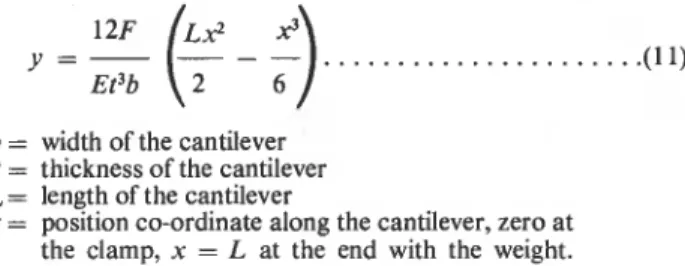
Substrate thickness was measured by micrometer. The modulus of the steel substrates varied enough to warrant measuring for each one used. If one end of the strip is clamped in place and a weight, F, is attached to the other end then the deflection, y, along the cantilever is given by Morley5 :
b = width of the cantilever
t = thickness of the cantilever
L = length of the cantilever
x = position co-ordinate along the cantilever, zero at the clamp, x = L at the end with the weight.
All the quantities in Equation (11) can be measured, permitting E to be determined. The value of E was typically 1.9 GPa. Poisson's ratio, v, of the steel was taken to be 0.29.
Resutts
The final, equilibrium, value of internal stress is plotted as a function of dried coating thickness in Figure 3(a) for the PIBM coatings and 3(b) for the PS coatings. There is no discernible trend with coating thickness for either coating, over the range of thicknesses employed.
Mean value of residual stress in PIBM = 5.6 MPa standard deviation = 0.3 MPa Mean value of residual stress in PS = 17.28 MPa standard deviation = 0.67 MPa PS coatings thicker than 18 pm spontaneously detached3 from the substrate and so could not be used to measure internal stress. Thinner coatings of PS adhered, but frequently crazed under stress, a well-known phenomenon. I N ITIAL SOLUTION CONCENTRATIONS, w/w
-
0 10% a30%
-
A35%
A 40%2
1
II
0
50
1 0 0 COATING THICKNESS,pm
Figure 3(a). Dependence of residual internal stress on coating thickness aad solution concentration in PIBM coatings
S. G. CROLL JOCCA Before a coating is completely dried, the solvent content
will vary with depth and thus internal stress will also vary through the coating. Consequently, deflection of the beam at intermediate times gives a value of internal stress averaged through the thickness of the coating; examples are given in Figures 4(a) and 4(b).
Discussion
In both lacquers the residual stress is independent of dried coating thickness and initial solution concentration over the ranges tested. The same features were present in residual strain measurements published previously8.
Additionally, the magnitudes of the residual strain (e) and stress can be compared. Stress-strain curves obtained for both PIBM and PS coating films were used in a pre- vious study3 and are reproduced here as Figures 5(a) and 5(b). Values obtained for the residual strains8 are:
PIBM, e = 5.8 x lC3 (+4.4 x 10⁻⁴) PS, E = 1.75 i c 2 (*I x 10-3
Using Figures 5(a) and 5(b), these correspond to stresses
(a') of:
PIBM, a' = 3.4 MPa PS, a ' = 10.9 MPa
I
A
5
CONCENTRATIONS. w/bt INITIAL SOLUTIONI 15'1. A 2 2 . 5 O I o A 30'1.
101
1 I 1 0 5 10 75 COATING THICKNESSp
Figure 3(b). Dependence of residual internal stress on coating thickness and solution concentration in PS coatings
TIME, h
Figure *a). Development of internal stress in PIBM lacquers, showing initial solution concentration (% w/w) and dried
coating thickness (urn)
Now the shrinkage in the coating is isotropic, so the film has two equal stresses or strains at right angles in the plane of the coating. In this plane stress situation
This adjustment is necessary because the residual strain and stress-strain curves are measured uniaxially whereas the bending plate determination of residual stress measures the combined effect of the stresses in the plane of the coating.
Poisson's ratio for the coatings has been given before8 as 0.4 for PIBM and 0.39 for PS. Equation 12(b) predicts that the residual stress measured should be 5.67MPa for the PIBM and 17.9 MPa for PS. The agreement is very good between values predicted from the residual strain and the values for residual internal stress measured. Crazing in PS does not influence the agreement between experiments.
Previously, the residual stress was measured for the same two lacquers using a cantilever substrate8. Values obtained then were 4.5 MPa for PIBM and 14.3 MPa for PS, about 20 per cent low in both cases. The discrepancy is probably due to the clamping of one end of the sub- strate, which restricts its bending. Presumably it restricts the bending arising from the component of stress across the width of the beam. .
Internal stress can be followed better as it increases with time in this type of experiment where changes in coating weight have no effect on the beam deflection. However, the experiment gives only the average value of internal stress because the coating dries at a rate that varies according to depth. This particular method seems to be more accurate and rather simpler than other, similar, methods. The coating can be horizontal, keeping its thickness even, and there is no need to weigh it to deter- mine the deflection caused by weight change.
As in investigations carried out previously on solvent cast coatings, the residual internal stresses or strains have been shown to be considerable. For PS coatings the inter- nal stress causes adhesive loss even in very thin coatings and is close to the maximum stress the films can bear (Figure 5), and which, in fact, often craze. Although the
-
A-
/ -
00- 0.1 I 1.0 10 I 100 I
TIME. h
Figure 4(b). Development of internal stress in PS lacquers, showing initial solution concentration (% w/w) and dded
1980(7) OVERHANGING BEAM METHOD FOR MEASURING STRESS
STRAIN,
'10Figure S(a). Uniaxial, relaxed stress-strain relationship for
PIBM films
adhesion of PIBM coatings is good, and the stress much lower than for PS, the residual stress is still a significant fraction of the maximum stress the films can withstand.
Conclusions
The overhanging beam configuration adopted here proved to be a simple and accurate apparatus for measuring inter- nal stress in coatings. The length of the centre span and overhang can be adjusted so that there is no deflection at the centre of the span due to weight loss from the coating. Displacement of the beam substrate at that position is due solely to internal stress in the coating. The change of average internal stress with time can be monitored well because the changing weight of the coating has no influence on the measurement.
As in the case of internal strain measurements, the residual stress proved to be independent of dried coating thickness and initial solution concentration. The mag- nitude of the residual stress predicted from the residual strain data was in close agreement with the value obtained from the overhanging beam configuration. The two measures of the same phenomenon proved to be consistent.
Employing the substrate as a cantilever yields values for internal stress that seem about 20 per cent lower. Clamp-
INTERNAL
'1
/
9 R A I N
STRAIN,
.loFigure 5(b). Uniaxial, relaxed stress-strain relationship for PS mms
ing one end probably restricts the bending deflection produced by a given stress in the coating, and hence the cantilever arrangement should be used with caution.
It can be seen, partidularly with the PS lacquer, that residual stress poses a considerable threat to the cohesive and adhesive properties of such coatings.
Acknowledgment
The author is grateful to Mr R. Myers for performing much of the experimental work described here. This paper is a contribution from the Division of Building Research, National Research Council of Canada, and is published with the approval of the Director of the Division.
[Received 30 January I980
References
1. Prosser, J. L., Mod. Paint and Coatings, 1977, 67(7), 47.
2. Croll, S. G., JOCCA, 63(6), 230.
3. Croll, S. G., Adhesion loss due to internal strain. To be
published.
4. Perera, D. Y., Private communication.
5. Morley, A., "Strength of Materials", 11th ed., Longmans, Green and Co. Ltd, 1954, London.
6. Aronson, P. D., JOCCA, 1974, 57(2), 66.
7. Corcoran, E. M., J. Paint Tech., 1969, 41(538), 635. 8. Croll, S. G., J. Coatings Tech. 1979, 51(648), 64.