READ THESE TERMS AND CONDITIONS CAREFULLY BEFORE USING THIS WEBSITE. https://nrc-publications.canada.ca/eng/copyright
Vous avez des questions? Nous pouvons vous aider. Pour communiquer directement avec un auteur, consultez la première page de la revue dans laquelle son article a été publié afin de trouver ses coordonnées. Si vous n’arrivez pas à les repérer, communiquez avec nous à PublicationsArchive-ArchivesPublications@nrc-cnrc.gc.ca.
Questions? Contact the NRC Publications Archive team at
PublicationsArchive-ArchivesPublications@nrc-cnrc.gc.ca. If you wish to email the authors directly, please see the first page of the publication for their contact information.
NRC Publications Archive
Archives des publications du CNRC
This publication could be one of several versions: author’s original, accepted manuscript or the publisher’s version. / La version de cette publication peut être l’une des suivantes : la version prépublication de l’auteur, la version acceptée du manuscrit ou la version de l’éditeur.
Access and use of this website and the material on it are subject to the Terms and Conditions set forth at
Development of a non-destructive procedure for estimating the length
of in-situ soil nails
Pernica, G.; Law, K. T.; Glazer, R.; Lee, C. F.; Tham, L. G.; Yue, Q.
https://publications-cnrc.canada.ca/fra/droits
L’accès à ce site Web et l’utilisation de son contenu sont assujettis aux conditions présentées dans le site
LISEZ CES CONDITIONS ATTENTIVEMENT AVANT D’UTILISER CE SITE WEB.
NRC Publications Record / Notice d'Archives des publications de CNRC:
https://nrc-publications.canada.ca/eng/view/object/?id=27f3f5c7-0218-40ce-ac1a-0347d4883890
https://publications-cnrc.canada.ca/fra/voir/objet/?id=27f3f5c7-0218-40ce-ac1a-0347d4883890
Development of a non-destructive procedure to
determine the length of in-situ soil nails
Pernica, G.; Law, T.; Glazer, R.; Lee, C.F.; Tham,
G.; Yue, Q.
NRCC-46089
A version of this document is published in / Une version de ce document se trouve dans :
55
thCanadian Geotechnical Conference, Niagara Falls, Ont., Oct. 20-23, 2002, pp. 1-8
DEVELOPMENT OF A NON-DESTRUCTIVE PROCEDURE TO
DETERMINE THE LENGTH OF IN-SITU SOIL NAILS
Gerry Pernica, National Research Council Canada, Ottawa, Ontario, Canada
Tim Law, Carleton University, Ottawa, Ontario, Canada
Rock Glazer, National Research Council Canada, Ottawa, Ontario, Canada
C. F. Lee, University of Hong King, Hong Kong
George Tham, University of Hong Kong, Hong Kong
Quentin Yue, University of Hong Kong, Hong Kong
ABSTRACT
Soil nails are used to stabilise soil embankments in the same way that rock anchors are placed to stabilise cuts into rock layers. Because of the large number of soil nails, which are installed every year in many parts of the world, particularly the Far East, a rapid and reliable method is desired to check the in-situ length of the nails. The industry tried to adopt the non-destructive sonic technique that measures the length of in-ground piles (ASTM D5882-00, Standard Test Method for Low Strain Integrity Testing of Piles) but the system showed severe limitations when it was applied to soil nails. A field procedure, which would reasonably estimate the lengths of installed nails, was therefore sought. This paper will present the difficulties encountered in trying to develop a practical test procedure using sonic wave techniques, the results of tests completed to date and the prospects for a successful outcome.
RÉSUMÉ
Les clous de sol permettent de stabiliser les remblais en terre de la même manière que les ancres de roche permettent de stabiliser plusieurs couches de roche. Étant donné qu’on installe un grand nombre de ces clous dans le sol chaque année aux quatre coins du globe et notamment en Extrême-Orient, on a besoin d’une méthode rapide et fiable afin de pouvoir en vérifier la longueur sur le terrain. L’industrie a tenté d’adopter une technique acoustique non destructive qui mesure la longueur des pieux fichés dans le sol (ASTM D5882-00, Standard Test Method for Low Strain Testing of Piles) mais cette technique s’est avérée très limitée dans le cas des clous de sol. On a donc cherché une procédure sur le terrain qui permettrait d’estimer convenablement la longueur des clous déjà installés. Cet article présente les difficultés rencontrées en essayant d’élaborer une procédure d’essais pratique utilisant la technique des ondes acoustiques, les résultats des essais effectués à ce jour et les perspectives de succès.
1. INTRODUCTION
Soil nails are used to stabilise soil embankments in the same way that rock anchors are placed to stabilise cuts into rock layers. Soil nailing is a simple, well-established method for reinforcing natural slopes in many parts of the world particularly in the Far East (e.g. Hong Kong, Malaysia etc.). About 100,000 nails are installed in Hong Kong each year to upgrade existing retaining walls and to reinforce natural slopes and man-made embankments. Nails range in length from 4 m to 20 m and comprise a steel rod (20-50 mm diameter) surrounded by a cementitious layer. The layer helps mitigate rod corrosion and increases the resistance between the nail and soil. The nails are installed by placing the rod into a predrilled hole and then pumping the cementitious material into the hole from the bottom upwards once the rod has been properly positioned
.
Because of the large number of soil nails, which are installed every year in places like Hong Kong, a rapid and reliable method is desired to check the length of in-situ nails before they are capped. Destructive techniques, such as the complete removal of randomly selected nails, have revealed that the lengths of installed nails may vary
considerably from that specified in the drawings. The industry tried to adapt the non-destructive technique that measures the length of in-ground piles (ASTM D5882-00), but the system showed severe limitations when it was applied to soil nails. An innovative technique, which would reasonably estimate the length of recently installed nails, was therefore sought.
Two sonic techniques, similar to ASTM D5882, were investigated with this objective in mind. The techniques, impulse response and steady-state forced vibrations, used hammer impacts and shaker excitations to input sonic waves into the nails. The techniques were conducted on four laboratory nails and on an in-ground soil nail at Institute for Research in Construction (IRC) of the National Research Council Canada (NRC), and on four recently installed nails on a slope in Hong Kong. The intent was to determine if the methods could be used to generate nail responses from which estimates of nail length were feasible.
This paper presents some of the difficulties encountered in using each technique, the results of tests completed to date and the prospects for the development of a practical test procedure using either of the techniques.
2. PRINCIPLES OF SONIC METHODS
2.1 Impulse Response
The test consists of striking the exposed end of the soil nail with an instrumented mechanical impactor, such as a hammer, and monitoring the dynamic response of the nail adjacent to the impact. The stress waves produced by the impact travel down the nail and are reflected back to the surface at interfaces produced by material dissimilarities within the nail, such as those encountered at the base of the nail (nail-soil interface). Upon returning to the surface of the nail (nail-air interface), the waves are in turn reflected back down the nail to be once again reflected back to the surface from material interfaces within the nail. The waves continue to travel back and forth between interfaces until the mechanical energy is dissipated by material and geometric damping within the nail-soil system. By recording the force and response generated by the impact and by analysing the two waveforms in the frequency domain, distances to major interfaces within the soil nail can be estimated from the frequency content of response spectra (Fourier transform or transfer function) and the wave velocity in the nail. If unknown, the wave velocity can be obtained by constructing a short nail sample and measuring the time required for an impact to travel the length of the sample. A more complete discussion of the impulse-response method can be found in most textbooks, which present non-destructive test methods for concrete and masonry components (Malhotra and Carino 1991, Sansalone and Streett 1997).
2.2 Frequency Response
The test consists of attaching a shaker to the exposed end of the steel rod and incrementally increasing the frequency of the forced vibrations to obtain the dynamic response of the soil nail over the selected frequency range. By recording shaker force and nail response and by analysing the signals on a frequency analyser, the dynamic properties of the soil-nail system are obtained from which estimates of nail length can be made. The method produces nearly the same normalised response spectrum (transfer function) as the impulse-response method for linear soil-nail systems. The difference between the two methods is in the amplitude and duration of the exciting force; the impact force produced by an instrumented hammer is typically much larger but of considerably shorter duration than the sinusoidal force generated by the shaker.
3. DESCRIPTION OF SOIL NAILS
3.1 In-Situ Nails in Hong Kong
The in-situ soil nails in Hong Kong were located on a slope in Kowloon (Fig. 1). At the time of the measurements, the 60-degree slope, about 100-m long and 45-m high, was being reinforced with hundreds of soil
nails consisting of steel rods encased in cementitious grout. Four consecutive nails near the 25-m level were selected for impulse-response testing. Frequency-response tests were not undertaken on these nails because of the limited force output of the shaker (5 N).
Figure 1. View of Soil Nail Site in Hong Kong
The steel rods within the nails were about 40 mm in diameter and 14-m long, consisting of the following three lengths of steel sections, 6 m, 4 m and 4 m, interconnected using patented steel couplers. The 6-m section was the first section inserted into the hole so that the connections between the sections were situated at 4 m and 8 m from the exposed end of the rod.
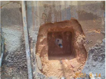
Figure 2. Preparation of Soil Nail for Installation of Concrete Cover Plate
The nails were relatively new as the grout had been pumped into the holes (about 125-mm in diameter) about four days earlier. Prior to the non-destructive tests, the contractor removed grout and soil surrounding the head of
concrete cover plate. The operation exposed about 150 mm of the steel rod (Fig. 2), consisting primarily of its threaded end.
3.2 Soil Nails at NRC/IRC
Four laboratory nails were constructed and tested using both sonic methods. The nails were viewed as the first step in examining the efficacy of the two test procedures and in developing a finite element model for the soil-nail system. The nails comprised steel rods, about 28-mm in diameter and 4.03-m long, encased in various configurations of normal weight concrete (Table 1).
Table 1. General Description of Laboratory Soil Nails Nail Description
A Rod exposed about 0.16 m at both ends of nail Concrete section about 3.7-m long
B Rod exposed about 0.16 m at both ends of nail Concrete section has centre gap of 0.5 m C Rod exposed about 0.17 m at one end of nail
Concrete section about 4.0-m long D Steel rod only
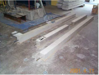
The concrete cover in Nails A to C (Fig. 3) had a 152-mm square cross-section and a compressive strength of about 20 MPa and thus was stronger, stiffer and denser than the grout in nails in Hong Kong. Nails A to C represented three possible arrangements for the cover material in in-situ nails; built as designed, discontinuous and continuous beyond the base of the steel rod.
Figure 3. View of Laboratory Soil Nails
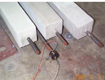
The in-ground nail installed at NRC/IRC comprised a 3.45-m long steel rod e3.45-mbedded vertically into the ground. The
clay leaving about 150 mm exposed for the tests.
4. MEASUREMENT PROCEDURE
4.1 Impulse Response
Tests on laboratory and in-situ nails were conducted by striking the exposed end of the nail and recording the time signatures of the impact force and nail response. Impacts were produced using a set of three instrumented hammers, each containing a force transducer in the striking head for measuring the induced force. The hammers varied in weight from about 0.3 kg to about 4 kg and each came equipped with several impact heads so that the amplitude and time duration of an impact could be varied. As a result, the set of hammers produced impacts, which covered a fairly wide range in both the duration and the amplitude of the force.
In general, the duration of an impact is dependent on hammer weight and head stiffness. Long duration impacts, i.e. impacts containing mainly low-frequency energy, are generated by heavy hammers equipped with soft impact heads whereas short duration impacts, impacts with broadband energy content, are produced by light hammers with stiff impact heads. Of the three instrumented hammers, the lightest hammer equipped with the stiffest impact head produced impacts with frequency content to about 10 kHz whereas the heaviest hammer with the softest head generated impacts that contained little frequency content above 500 Hz.
Figure 4. In-ground Soil Nail at NRC/IRC Undergoing Impulse-Response Test with Small Hammer
In the tests, the goal was to generate impacts containing energy from 0-3 kHz for both the laboratory and in-ground nails at NRC/IRC and 0-1 kHz for the nails in the slope in Hong Kong. The noted frequency ranges were based on the desire to excite several of the higher modes
associated with the response of the nail and not the nail-soil system. The hammers either impacted the nail directly (most of the time) or indirectly by inserting a short aluminum shaft, about 150-mm long, between the hammer and the nail. The bevelled end of the shaft was held firmly against the nail to prevent the shaft from moving when hit.
The response of the nail in its longitudinal direction was obtained by attaching an accelerometer to either the steel rod (Fig. 4) or the material surrounding the rod. The sensor was connected using different attachment techniques so as to evaluate and thus determine the most effective way of monitoring the response of the nail to impacts. Table 2 notes the various techniques examined to attach the accelerometer to the nail.
Table 2. Techniques for Mounting Accelerometer on Nail Location
on Nail
Mounting Technique
Cover • Sensor on magnetic base - base set on head of screw inserted into cover • Sensor attached to probe (steel rod with
pointed tip) – probe held firmly against cover in direction of nail
Steel Rod • Sensor on magnetic base - base set on end of steel rod
• Sensor attached to probe – probe held firmly against end or side of rod
• Sensor on magnetic base placed on
steel nuts – nuts screwed tightly onto threaded portion of rod
Two types of piezo-electric accelerometers were used to monitor the response of the nails to hammer impacts. The two, which had similar physical dimensions and dynamic response characteristics, were selected because of their broadband frequency (1 Hz–20 kHz) and full-scale acceleration ranges (500–1000 g). The bottom of each was fitted with a 4-40 screw so that it could be firmly attached to any structure with a threaded fitting (e.g. a magnetic base).
Different combinations of sensor and impact locations, and sensor attachments to the nail were investigated in an attempt to determine the optimum test procedure for the impulse-response tests. Table 3 lists the various combinations tested during the study to date.
Signals from the instrumented hammer and accelerometer were fed into a 2-channel frequency analyser with signal storage capabilities. The sampling rate was set by the frequency range selected for the measurement, which depended on the type of hammer and head selected for the impact. For nearly all impacts, the frequency range was set to either 2 kHz or 5 kHz with the 5 kHz range
being used primarily for the in-ground and laboratory nails at NRC/IRC.
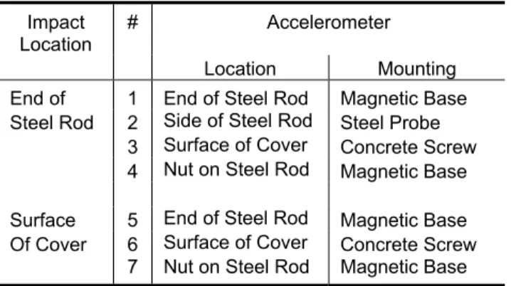
Table 3. Tested Combinations of Impact and Sensor Locations, and Mounting Techniques
Impact Location
# Accelerometer
Location Mounting
End of 1 End of Steel Rod Magnetic Base
Steel Rod 2 Side of Steel Rod Steel Probe
3 Surface of Cover Concrete Screw
4 Nut on Steel Rod Magnetic Base
Surface 5 End of Steel Rod Magnetic Base
Of Cover 6 Surface of Cover Concrete Screw
7 Nut on Steel Rod Magnetic Base
The analyser displayed the waveforms, generated by the impact, and frequency spectra (Fourier transforms and transfer function) derived from the time signals using algorithms built into the analyser. Not all captured signals were stored in the analyser for future analysis and display. After each impact, a decision to accept or reject the measurement for suitability and usefulness in identifying the desired modal properties of the soil nail was taken, based on the time and frequency signatures of the two recorded signals. In many instances, the test was rejected because the nail was struck improperly by the hammer (e.g. impact head hit nail twice or at a noticeable angle). Figure 5 depicts the measurement procedure used in the execution of a test.
MEASUREMENT PROCEDURE 1. Select Hammer Type and Impact Head
Hammer: Small, Medium or Large
Head: Steel or Stiff/Medium Plastic
2. Attach Accelerometer to Soil Nail
Location: Steel Rod or Cover
Mounting: Magnetic Base or Probe
3. Strike Soil Nail on Steel Rod or Cover 4. Capture Force and Accelerometer Signals 5. Display Signals in Time and Frequency Domains 6. Accept or Reject Measurement
7. Identify Modes in Transfer Function Useful for Estimating Length of Soil Nail
Impulse-Response Tests on Soil Nails
No attempt was made at this point in the development of the procedure to estimate the actual length of the nail. The present goal was simply to determine if the procedure could excite modes useful for estimating the length of the nail and if so, for which nail lengths, covers and in-situ conditions.
4.2 Frequency Response
Frequency response tests were performed on the four laboratory nails and in-ground nail at NRC/IRC by attaching a small high-frequency shaker (0.02-20 kHz) to the end of each steel rod (Fig. 6). The longer nails in Hong Kong were omitted since the force of the shaker (5 N) was considered too small to excite the entire nail.
Figure 6. Small High-Frequency Shaker Attached to Laboratory Nail D
The shaker contained a built-in impedance head, comprising a force transducer and an accelerometer, which monitored both the force exciting the rod and the response of rod to the force. A signal generator within the 2-channel analyser was programmed to slowly increment the frequency of the steady-state signal being fed into the shaker over the frequency range selected for the test. Tests on the nails were conducted over several ranges with the most common being 0.1-5 kHz.
The signals from the impedance head sensors were fed into the 2-channel analyser for display, analysis and storage. The analyser displayed the waveforms generated by the shaker and frequency spectra (Fourier transforms and transfer function) derived from the set of sinusoidal vibrations. The transfer function was examined (as was the case with the impulse-response technique) to determine the suitability of the modal responses in estimating the length of the nail. Figure 7 depicts the
test.
MEASUREMENT PROCEDURE 1. Attach Shaker to Rod of Soil Nail
2. Conduct Steady-State Forced Vibrations over Selected Frequency Range
3. Capture Force and Accelerometer Signals on 2-Channel Frequency Analyser
4. Display Fourier Transforms and Transfer Function 5. Identify Modes in Transfer Function Useful for
Estimating Length of Soil Nail
Figure 7. Measurement Procedure for Conducting
Frequency-Response Tests on Soil Nails
5. RESULTS AND OBSERVATIONS
5.1 Impulse Response
5.1.1 Soil Nails at NRC/IRC
Measurements were conducted on the in-ground and laboratory nails using the small hammer equipped with either the steel or hard plastic impact head. The nails were struck by impacting the end of the steel rod or the surface of the concrete cover beside the rod. The accelerometer was placed in contact with the nail using a magnetic base for the rod and the steel probe for the surface of the concrete.
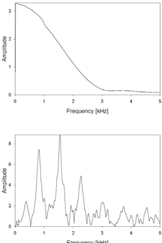
Figures 8 and 9 show the Fourier transforms of the force and nail responses to impacts conducted on the two nails composed only of steel rods, namely, Nail D and the in-ground nail. The frequency range of the analyser was set to 5 kHz because the predicted spacing of the higher modes (Malhotra and Carino 1991) was about 630 Hz for the 4-m rod (Nail D) and 730 Hz for the 3.45-m in-ground rod. The same frequency range was also used for Nails A to C even though a smaller frequency spacing for the higher modes was estimated for these nails because of their composite construction.
Frequency spectra indicated that impacts generated by the small hammer were capable of exciting the desired higher modes in all NRC/IRC nails. Peaks in response spectra, which identify nail modes, were better defined in the laboratory nails than in the in-ground nail because of the resistance and damping provided by the soil. What the figures do not show is the difficulty encountered in reproducing a satisfactory impact with the hand-held hammer when striking either the steel rod or the concrete cover. As the impact head could strike the nail at a
slightly different location or angle each time an impact was performed, numerous attempts were required on all but the simplest nail (Nail D) to replicate frequency spectra with suitably defined higher modes. Analysis techniques to improve the quality of frequency spectra, such as averaging spectra, could not be used since the impacts themselves were not repeatable.
Figure 8. Fourier Transforms of Force (Top) and Rod Response (Bottom) for Impact on Nail D
For the composite nails, striking the concrete cover and monitoring the response of the rod produced more satisfactory frequency spectra than striking the rod and monitoring either the rod or the concrete cover. Part of the problem in striking and monitoring the rod lay in the closeness of the accelerometer to the impact. The nearness produced large amplitude responses which may not to be totally related to the longitudinal response of the nail but which dominated the initial portion of the time signature. The difference between monitoring the rod and the concrete cover was that the magnetic base was a more suitable mount than the probe (frequency range <1 kHz) for capturing the high-frequency responses of the nail.
5.1.2 In-Situ Nails in Hong Kong
Impulse-response measurements on four of the 14-m long nails in Hong Kong were conducted using the medium and large instrumented hammers equipped with either steel or medium/stiff plastic impact heads. Impacts were delivered either to the end of the rod or to the surface of the grout. At the start of testing in Hong Kong, the aluminum shaft was also used as an extension platform for impacting the nails indirectly. However, its use was soon discontinued as the base of the device had a tendency to slide along the surface of the nail (either the rod or the grout) when the device was struck by the hammers.
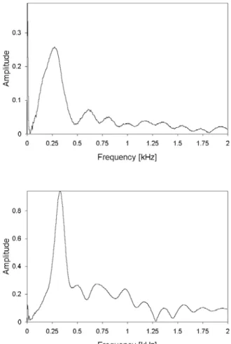
Figure 9. Fourier Transforms of Force (Top) and Rod Response (Bottom) for Impact on In-Ground Nail
Nail responses were again obtained by monitoring the rod or the surface of the grout. Responses were captured with an accelerometer mounted on either a steel probe or a magnetic base (Table 2). However, because of the difficulty in holding the probe stationary against the nail, the probe was only used to monitor the response of the rod when the rod was struck by the hammer. Problems were also encountered using the magnetic base.
the magnetic base sometimes moved when the accelerometer was positioned on the end of the rod for grout impacts.
No decision was made on the suitability of monitoring the response of the rod by mounting an accelerometer on a pair of nuts screwed tightly onto the rod, as the frequency range containing the desired higher modes of the 14-m long nails was still uncertain at this time.
At the start of the testing program, the grout was also considered a suitable location for monitoring the response of the nail. However, during testing, it became evident that the grout should be avoided as the surface layer in some of the nails contained hairline cracks. The cracks may have been produced by the impacts themselves or the way (noted below) in which the nail was prepared for the installation of a concrete cover plate.
The outer 15-20 cm of grout, which covered the threaded end of the rod following the placement of the grout, was removed manually with a pick and hammer. As the grout was still relatively young when this task was undertaken (about 72 hours later), there was a reasonable likelihood that the process may have damaged the top layer of the remaining material.
Several tests were consistently required to properly reproduce impacts using the medium and large hammers. The difficulty in striking either the end of the rod or the grout in a consistent manner was more apparent with the large hammer because of its size and the awkward location of the nail within the soil opening. For this reason and because the large hammer was generally less successful than the medium hammer in exciting the desired modal frequencies, its use was discontinued midway through the testing program.
Figure 10 shows the Fourier transforms of impact-induced rod responses in two of the in-situ nails. The nails, which lay adjacent to each other on the slope, produced similar frequency responses to impacts delivered to the end of the rod using the medium hammer equipped with the medium-stiff impact head. The frequency range on the analyser was set to 2 kHz because of the length of the nails and the uncertainty as to whether the nails would show dynamic behaviour similar to that of a steel rod or a composite nail.
The medium hammer with the medium-stiff head appeared most suitable for exciting the higher modes of the 14-m long nails based on an examination of all impacts conducted on the four in-situ nails. In responses
produced by this impact arrangement (Fig. 10), the
spacing of modal peaks above 500 Hz suggested a dynamic behaviour that was more in keeping with rod than composite nail behaviour. However, until a finite-element model of these nails is constructed and calibrated, and various parametric analyses undertaken, it is still uncertain as to whether these peaks actually correspond to the higher modes of the in-situ nails.
5.2 Frequency Response
Measurements were conducted on the in-ground and laboratory nails at NRC/IRC using a small shaker with a built-in impedance head. The shaker was tightly screwed to the centre of the steel rod and the frequency of the forced vibrations incrementally increased over the selected frequency range. For most of the tests, the shaker was operated at near maximum output to ascertain whether the small device was capable of exciting the higher modal frequencies of these relatively short nails (≤ 4 m long
).
Figure 10. Fourier Transforms of Impact-Induced Rod Responses in Two In-situ Nails in Hong Kong
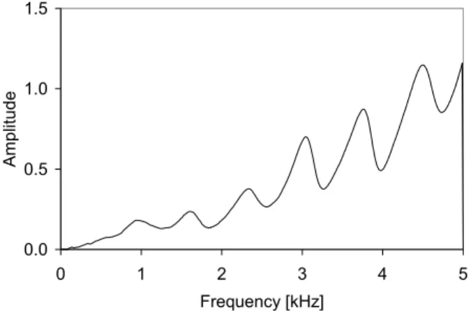
Figure 11 shows the transfer function obtained for the in-ground nail for forced vibrations from 0.1-5 kHz. Higher modal frequencies are readily visible within the spectrum. The spacing of the modes (about 710 Hz) also correlates well with the dynamic properties of the 3.44 m long steel rod.
Nearly identical spectra were obtained when the test was repeated for the in-ground nail over the same frequency range and over other ranges containing all or portions of the 5 kHz range. However, spectra obtained for the three laboratory nails with concrete covers were not as encouraging, as the higher modal frequencies of these nails were difficult to identify within the transfer functions produced by the small shaker. Whether the method is appropriate for soil-nail systems even if larger shakers were attached to the rod remains uncertain at this point in the study. 0.0 0.5 1.0 1.5 0 1 2 3 4 5 Frequency [kHz] Amplitude
Figure 11. Transfer Function for Response of In-Ground Soil Nail at NRC/IRC to Steady-State Excitations
6. CONCLUSIONS
The impulse-response method appears capable of determining the length of in-situ soil nails but more appropriate devices are required to attach the accelerometer to the steel rod and to deliver repeatable, reproducible impacts.
Existing responses need to be reanalysed and additional tests need to be undertaken to determine if the frequency-response method can identify the higher modal frequencies of the 4-m long laboratory nails using the small shaker.
A finite-element model of the soil nail is required to verify the efficacy of the two sonic methods in exciting modal frequencies from which meaningful estimates of nail length can be made.
7. REFERENCES
ASTM 2000. Standard Test Method for Low Strain
Integrity Testing of Piles, ASTM D5882-00. American
Society of Testing Materials, Philadelphia, Pennsylvania
Malhotra, V.M. and Carino, N.J. (Editors) 1991. CRC
Handbook on Nondestructive Testing of Concrete. CRC
Press, Boca Raton, Florida, 343 p.
Sansalone, M.J. and Streett, W.B. 1997. Impact-Echo:
Nondestructive Evaluation of Concrete and Masonry.