HAL Id: hal-01264434
https://hal.inria.fr/hal-01264434
Submitted on 29 Jan 2016
HAL is a multi-disciplinary open access
archive for the deposit and dissemination of
sci-entific research documents, whether they are
pub-lished or not. The documents may come from
teaching and research institutions in France or
abroad, or from public or private research centers.
L’archive ouverte pluridisciplinaire HAL, est
destinée au dépôt et à la diffusion de documents
scientifiques de niveau recherche, publiés ou non,
émanant des établissements d’enseignement et de
recherche français ou étrangers, des laboratoires
publics ou privés.
Model-Based Identification of Anatomical Boundary
Conditions in Living Tissues
Igor Peterlik, Hadrien Courtecuisse, Christian Duriez, Stéphane Cotin
To cite this version:
Igor Peterlik, Hadrien Courtecuisse, Christian Duriez, Stéphane Cotin. Model-Based Identification of
Anatomical Boundary Conditions in Living Tissues. IPCAI 2014 - 5th International Conference on
Information Processing in Computer Assisted Interventions, Jun 2014, Fukuoka, Japan.
�10.1007/978-3-319-07521-1_21�. �hal-01264434�
Model-Based Identification of Anatomical
Boundary Conditions in Living Tissues
Igor Peterlik1,2,4, Hadrien Courtecuisse1,2,3, Christian Duriez2, and
Stéphane Cotin1,2
1
Institut Hospitalo-Universitaire, Strasbourg, France
2
SHACRA Team, Inria, France
3
AVR Team, CNRS, France
4
Institute of Computer Science, Masaryk University, Czech Republic
Abstract. In this paper, we present a novel method dealing with the identification of boundary conditions of a deformable organ, a partic-ularly important step for the creation of patient-specific biomechani-cal models of the anatomy. As an input, the method requires a set of scans acquired in different body positions. Using constraint-based finite element simulation, the method registers the two data sets by solving an optimization problem minimizing the energy of the deformable body while satisfying the constraints located on the surface of the registered organ. Once the equilibrium of the simulation is attained (i.e. the organ registration is computed), the surface forces needed to satisfy the con-straints provide a reliable estimation of location, direction and magnitude of boundary conditions applied to the object in the deformed position. The method is evaluated on two abdominal CT scans of a pig acquired in flank and supine positions. We demonstrate that while computing a physically admissible registration of the liver, the resulting constraint forces applied to the surface of the liver strongly correlate with the loca-tion of the anatomical boundary condiloca-tions (such as contacts with bones and other organs) that are visually identified in the CT images.
1
Introduction
In the last decade the role of computer medical simulation in surgical training, pre-operative planning and intra-operative guidance has increased considerably. A key factor to the successful use of numerical simulation in medicine is the ability to reproduce the complex behavior of anatomical structures. For soft tis-sues, the models are usually based on elasticity theory, which provides powerful means of modeling the behavior of soft tissues often displaying complex charac-teristics such as incompressibility or viscoelasticity. Since the equations derived in the theory of elasticity can be solved analytically only for extremely simple scenarios, numerical methods such as the finite element (FE) method must be employed to solve the problem over a discretized domain.
While an interesting body of research exists regarding domain discretiza-tion and appropriate formuladiscretiza-tion of the physical behavior of living tissues, much
less attention has been paid to correct modeling of boundary conditions which influence the model significantly, as they directly determine the particular solu-tion to the overall physical problem. In the domain of patient-specific medical simulations, an attempt to fill this gap becomes really challenging: while the ge-ometrical and physical properties of the living tissues can be obtained either via medical imaging or rheology experiments, it is usually very difficult to obtain re-liable data describing the interactions between different regions of living tissues, since these can be given by a complex combination of bilateral constraints (rep-resented for example by ligaments and connective tissues) or unilateral contacts induced by tissue motion (such as respiratory motion, application of external forces or displacements of organs during the surgery).
In this paper, we focus on identification of boundary conditions from medical image data. We propose a method which, given two (or more) different config-urations of the same three-dimensional deformable structure, is capable of (i) registering the two volumes using a physically-admissible transformation, (ii) providing a set of surface forces which correspond to the boundary conditions of the object in the target configurations. Although our method requires a construc-tion of a FE model (usually obtained via segmentaconstruc-tion and mesh generaconstruc-tion), to our best knowledge, it is the first technique allowing for automatic identification of boundary conditions from image data.
2
Related Work
The identification of boundary conditions (BCs) has been studied in the area of structural analysis and computer-aided design. For example, in [1] BCs are identified using a boundary stiffness matrix which is obtained as a solution of characteristic equations formulated for different modes of the object. The char-acteristic equations are non-linear and their number corresponds to the number of boundary degrees of freedom. Nevertheless, it is supposed that the object is modeled using linear elasticity and the BCs also behave linearly. In [2], accurate determination of BCs including non-linear effects as friction and slip is presented for 2D circular plate. In [3], the non-linear effects are also taken into account in a method based on non-linear normal modes allowing also object with non-linear response; the method is validated using a simple beam. While these methods allow for a very accurate identification of BCs, they can be employed only in the scenario where the objects have a simple and well-defined boundaries. Although the non-linear effects are considered, the type of interactions is usually limited to bilateral constraints with micro-slip. However, this is usually not the case in medical simulations where objects having complex boundaries are involved in different types of interactions including both bilateral and unilateral constraints with and without friction (for example simulatio of abdominal organs).
In the case of soft-tissues, the currently used imaging modalities such as CT, MRI and ultrasound allows for reconstruction of the geometry of the bodies in the scanned volume. However, in order to obtain more information about the motion of the tissues, at least two scans acquired in two different configurations
are needed. Nevertheless, in this case, a registration has to be performed in or-der to find a transformation between the two configurations. In the following we briefly survey relevant methods presented in the area of deformable registration, usually in context of preoperative planning and intra-operative guidance [4]. A 3D registration of intra-operative MR brain images is proposed in [5]: the model is based on linear elasticity discretized by the finite element method. The method is driven by active surface matching which deforms the boundary of brain in one acquired image towards the boundary in the following scan. The image warping based on finite element method is developed in [6]. The hyperelastic formula-tion is employed and the warping is applied in several domains, e.g. to measure strain in coronal artery or quantify morphology changes in mouse brain. A multi-organ deformable image registration based on mechanical model simulated with finite elements is developed in [7]. The model driven by surface deformation and displacements of landmarks is used to analyze and predict the motion of abdom-inal organ during respiration. Minimization of landmark displacements is used to drive the deformable registration of mouse brain in [8]: several regularization terms based on finite element formulation are compared including diffusion, lin-ear and non-linlin-ear elasticity. In [9], the BCs are estimated by solving an inverse problem optimizing for different explicitly chosen factors causing the brain shift. While in this scenario, different a priori chosen distributions of various BCs are evaluated as independent model solutions using the cost function, our method is based on a direct solution of the constrained system where no assumptions about the type and distribution of the BCs are made.
In [10], a model-based method using iterative closest point was presented for registration of muscular structures. In [11] preoperative 3D CT images are reg-istered to either 3D or 2D intra-operative scans. While the registration is driven by optimization of similarity metrics (squared differences, mutual information and correlation ratio are considered), the mechanical model based on linear elas-ticity is used to regularize the solution. The method is tested on breast phantom. Multi-modality registration for image-guided prostate intervention is described in [12]: in the preoperative phase, a finite element patient specific model is built using the preoperative MR data and a set of deformations corresponding to differ-ent BCs and randomly sampled material properties are computed and evaluated statistically using PCA.
Although the referenced methods often provide accurate and physically-admissible transformation betweens the registered domains, to our best knowl-edge, none of the methods allows for reliable identification of BCs without any a priori assumptions about the BC type and placement.
3
Methodology
Our approach is based on the technique presented in [13] where the method is used to compute a model-based registration between pre-operative data acquired by 3D CT and intraoperative 2D MRI slices. The main contribution of this paper is a generalization of the method so that given a discrete representation of the
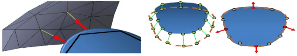
Fig. 1. The control points (grey) are as-sociated to the closest point of the cu-bic interpolation (blue) of the FE surface (black). Constraints (red) are define along the direction of the the segment connect-ing the two models (green).
Fig. 2. Binding process (left) and con-straint force evaluation (right) to register a deformable object (blue) with the con-trol surface (brown). The Gauss-Seidel al-gorithm iteratively activates (red) or deac-tivates (gray) the constraints according to the actual respective violations.
registered object in both configurations, the method provides automatically i) physically-valid registration of the object in the two different configurations and ii) identification of bilateral and unilateral boundary conditions applied to the object in the target configuration.
3.1 Binding process and constraints definitions
The method takes on one side the triangulated surface of the target and on the other side the FE mesh in a different position. The iterative closest point (ICP) method [14] is used to associate the set of control point (from the target surface) with their respective closest points on the surface of the simulated FE. The method is improved by using a cubic Bézier interpolation of the FE surface as described in [15]. It provides a smooth description of the triangulation allow-ing for a continuous slidallow-ing of the constraints between edges and triangles (see Fig.1), which helps to stabilize the registration. The barycentric coordinates of the closest point on the cubic interpolation of the triangles are determined with the Newton-Raphson algorithm.
At each time step, the control points qi are associated to their respective
closest points qson the Bézier path. For each point qs, the normal nsis evaluated
on the Bézier interpolation. A set of bilateral constraints is defined so that the constraints be satisfied for qi located on the tangential plane given by ns.
This formulation allows the control points to “slide” on the surface of the FE mesh in order to stabilize around the configuration minimizing the energy and satisfying the constraints. Since the proximity-based information is formulated in the contact space, it has to be mapped to the standard 3D space of the FE mesh via a mapping matrix J linking the positions in the contacts space to the 3D space of the object (see [16]). For the violation of the constraints δ it holds:
3.2 Constraint-based simulation
The deformation of the tissue is modeled with linear tetrahedral finite elements employing the co-rotational formulation [17]. While handling large displacements properly, it is restricted to small strains. Constraints are imposed using the Lagrange multipliers. Denoting the time as t, the governing differential equation in a quasi-static scenario is given by:
f (qt) + f + JTλ = 0 (2)
where f are external forces (such as gravity), f (qt) are the internal volume forces
at a given position q. JT and λ are respectively the Jacobian of the constraints and the force used to drive the registration. This equation is solved with the Schur complement method (see [16] for details). It involves mainly two steps: i) during the free motion, a step of the simulation is computed without imposing any constraints. This operation requires the solution of a sparse linear system of equations which is done using conjugate gradients. ii) During the corrective motion, the control points are binded to the closest surface and constraint forces are evaluated to correct the free motion. The constraint forces are obtained by solving a constrained problem W λ + δ = 0 where W is the Delassus opera-tor [16], which defines the coupling of the constraints given by the domain of the deformable body. The resulting contact forces λ are obtained with an iter-ative approach based on the Gauss-Seidel method where constraints are treated sequentially one at the time. Depending on the violation of the constraints, each equation is either activated with a non-zero force or deactivated if the violation is zero (see Fig. 2). As a result, only the constraints necessary to suppress the violation are active, and λ minimizes the energy required to cancel the con-straint violation δ. Therefore, when comparing to the penalty-based methods, the actual approach employing the compliance (encoded in W) minimizes the forces needed to impose the constraints, which in turn leads to a more accurate identification of the boundary conditions.
4
Results
We now evaluate our method in several scenarios: first, we investigate two aca-demic examples to demonstrate the efficiency and the accuracy of the method. In the second part of the section we apply the method to a CT data of a female pig liver in other to show an important match between the predicted surface loads and real boundary conditions induced by the surrounding tissues.
4.1 Accuracy and efficiency of the method
For the sake of validation, the method is evaluated using data generated by a simulation (denoted as direct ) which takes an initial configuration of a simple-shaped beam object and computes a target configuration induced by gravity and interaction with other solid bodies. Beside the shape of the deformed object in
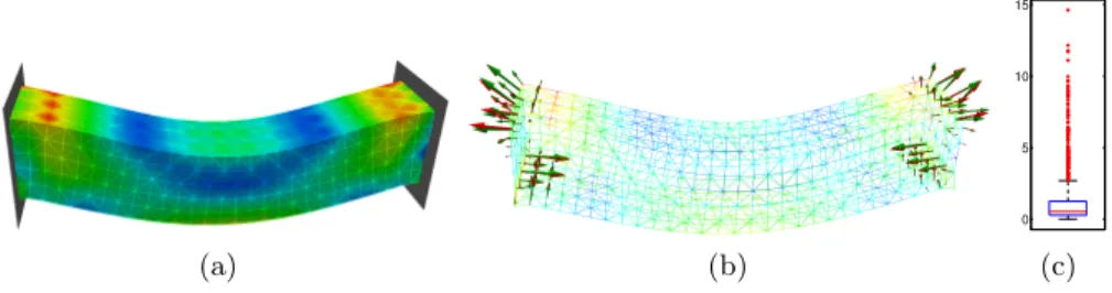
(a) (b) 0 5 10 15 (c) Fig. 3. Deformable beam attached at both extremities under gravity: (a) von Mises stress in the target configuration, (b) surface constraint forces corresponding to tar-get configuration (red) and registered configuration (green).(c) box-and-whisker plot showing the statistics of the von Mises stress error.
target configuration, the constraint forces computed by the direct simulation are stored for the validation step. Next, the initial configuration of the beam is registered to the target configuration using the method presented in section3. It should be emphasized that in this step, no information about the applied forces and loads, boundary conditions and other solid objects involved in the direct simulation is used and the only input of the procedure is the geometric representation of the beam in initial and target configurations and its physical parameters used in the direct simulation. As soon as the dynamic equilibrium is achieved, the resulting registered configuration is stored together with the constraint forces.
The validation consists of comparing (i) von Mises stress computed in the nodes of the mesh and (ii) surface constraint forces obtained in the target con-figuration and registered concon-figuration. While the forces are compared visually, the von Mises stress is evaluated for node n using a relative error Eσn=|σnr−σnt|
σn t
where σnt is the nodal stress in target configuration and σnr is the nodal stress in the registered configuration. The vector of errors for each case is statistically evaluated over the set of nodes, computing the mean ¯Eσand maximum ˆEσvalue
and displaying the standard box-and-whisker plot where values exceeding the er-ror given by q3+ 1.5(q3− q1), q1 and q3 being first and the third quartiles, are
considered as the outliers.
In the first scenario depicted in Fig. 3(a), the beam composed of 4350 el-ements and 1080 nodes is deformed under gravity, being attached at both ex-tremities with fixed constraints which prevent the motion of all nodes located on the corresponding faces of the object. The visualization of the constraint forces (Fig.3(b) shows a good match between the target and registered configuration. As for von Mises stress error, ¯Eσ = 0.1%, ˆEσ = 14.6% and Fig. 3 shows 139
outliers (among the 1080 nodes) with error exceeding 2.7%.
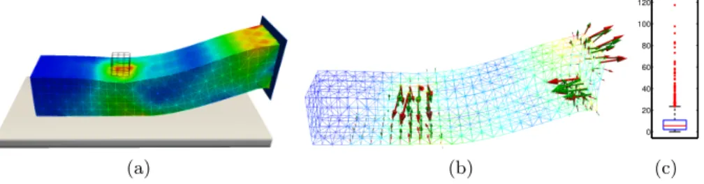
In the second scenario, the same beam is also subjected to the gravity, how-ever, only one extremity is fixed. Moreover, the bottom face of the beam col-lides with a supporting plane and a solid cube falls on its top face as shown in Fig.4a. Thus, the target configuration is a result of a complex set of bilateral
(a) (b) 0 20 40 60 80 100 120 (c) Fig. 4. Deformable beam under gravity in interaction with supporting plane and the cube: (a) von Mises stress in the target configuration, (b) surface constraint forces corresponding to target configuration (red) and registered configuration (green), (c) box-and-whisker plot showing the statistics of the von Mises stress error.
and unilateral constraints. The visualization of surface forces reconstructed by the registration method is shown in Fig. 4b. The statistical evaluation of von Mises stress results in ¯Eσ = 8.5%, ˆEσ = 117.3% and Fig. 3c shows 62 outliers
(among 1080 nodes) with error exceeding 23.8%. Although the statistics of the von Mises error shows worse results in the seconds case, the location of the sur-face loads is predicted quite accurately and we assume that the differences in the von Mises stress rather reflect different orientations of the loads, as indicated by the arrows shown in Fig.4c.
4.2 Estimation of boundary conditions of living tissues
The CT scans of a female pig in flank and supine positions were acquired with SOMATOM® Definition AS 128 device. Semi-automatic segmentation of liver were performed in both volumes using ITKSnap. In both volumes, surface mesh was extracted from the segmented maps and in the case of supine data, also the volume mesh was generated using CGAL library resulting in 6506 elements. The method described in section3was applied to the discretized data to register the shape of the liver from supine (source) to the flank (target) configuration and to identify the boundary conditions once the equilibrium of the simulation was attained. The deformation field given by the difference of source and registered meshes was then used to warp the source image in order to perform the evaluation of the registration. The surface forces were displayed to asses the method visually as no ground truth exists in the case of medical data.
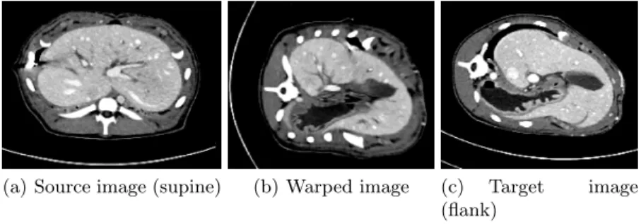
First, the visual comparison of one slide showing the source, warped and target images is presented in Fig.5. Moreover, the deformation field was used to warp also the segmented maps, which enabled us to evaluate the segmentation using Dice metric describing the overlap between two binary images. While the Dice coefficient of 47% was computed for the overlap between the source (non-registered) and target data, the coefficient attained 87% when registered and target data were compared. Given the magnitude of initial deformation, the registration clearly gives very good result both in term of quantitative and visual comparison.
(a) Source image (supine) (b) Warped image (c) Target image (flank)
Fig. 5. Illustration of the accuracy of the registration for a cut in the source, warped and target volume.
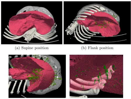
The supine and flank configurations are displayed on Fig.6ab showing an important deformation of the liver and surrounding tissues due to the impor-tant deformation of the rib cage. The overall image of the predicted surface loads is given in Fig. 6b. First, it should be recalled that unlike the case in the previous section, neither supine nor flank data provide the configuration which corresponds to the rest position of the liver. In fact, this position is not known, since in both supine and flank configuration, the liver is subjected to gravity and to the surface loads induced by the surrounding objects. Therefore, rather than identifying the absolute surface loads in the target configurations, a relative dif-ference in loads applied in supine and flank configurations is obtained indicating the change in boundary conditions. We believe that the estimation of absolute surface loads could be obtained by comparing several different configurations, where the influence of the applied loads and forces could be filtered.
Two details of predicted surface loads are shown in Fig.6c and6d. In the first case, the loads that appeared due to the contact with stomach (visceral surface) and diaphragm (diaphragmatic surface), in the other case, interaction between the liver and stiff bodies of ribs are clearly indicated. Apparently, all these loads can be logically justified due to the rotational movement of the liver which occurred during the change of the pig’s position from supine to flank configuration: while in the supine position, the lateral surfaces of the liver lobes are not subjected to important contact loads, since the mass is pressing mainly the posterior part of the organ against the spine, in the flank position, important contacts occurs between the left part of the liver and the ribs.
5
Discussion and Conclusion
The precise estimation of boundary conditions in soft tissues plays a crucial role in computer simulation-based planning and guidance. For example, in the case of surgical navigation based on augmented reality, a biomechanical model can be used to predict the actual position of the tumor inside the tissue. In this paper, we propose a model-based method allowing for joint registration and prediction of
(a) Supine position (b) Flank position
(c) Predicted surface loads (stomach) (d) Predicted surface loads (ribs) Fig. 6. Evaluation of the method on porcine liver deformation induced by re-positioning the pig from supine to flank positions (a,b). Details of predicted surface loads (c,d).
surface loads in the deformed configuration which can be directly used to identify boundary conditions. The method was validated employing two scenarios with a beam object, where the deformations were computed via simulation in order to have both the deformed shape and surface loads in the target deformation. The data was used as a ground truth and compared to the von Mises stress and surface loads obtained in the registration process. The method was demonstrated on a real medical data of female pig scanned in supine and flank positions in order to induce important deformations of the abdominal cavity. To our best knowledge, no attempt has been made so far to predict the surface loads inside a living body using only the scanned images without any a priori assumption. The evaluation has proven that the method is capable of predicting the difference in surface loads applied to the liver and this data can be straightforwardly used to identify boundary conditions in the target configuration.
We are aware of the fact that while different loading scenarios would further increase the accuracy of our method, it requires multiple acquisitions which are usually not available in humans. Nevertheless, while keeping in mind the patient specific scenario, we would also like to employ an intra-patient evaluation based on atlas, which could provide a base for the BC estimations (e.g. placement of the ligaments and other connective tissues with lower intra-subject variance).
References
1. Ahmadian, H., Mottershead, J., Friswell, M.: Boundary condition identification by solving characteristic equations. J. of Sound and Vibration 247(5) (2001) 755–763 2. Suzuki, A., Kamiya, K., Yasuda, K.: Identification technique for nonlinear bound-ary conditions of a circular plate. J. of Sound and Vibration 289(1–2) (2006) 130–147
3. Ahmadian, H., Zamani, A.: Identification of nonlinear boundary effects using non-linear normal modes. Mechanical Systems and Signal Processing 23(6) (2009) 2008 – 2018 Special Issue: Inverse Problems.
4. Carter, T.J., Sermesant, M., Cash, D.M., Barratt, D.C., Tanner, C., Hawkes, D.J.: Application of soft tissue modelling to image-guided surgery. Medical engineering & physics 27(10) (December 2005) 893–909
5. Ferrant, M., Nabavi, a., Macq, B., Jolesz, F.a., Kikinis, R., Warfield, S.K.: Regis-tration of 3-D intraoperative MR images of the brain using a finite-element biome-chanical model. IEEE Trans. on Medical Imaging 20(12) (2001) 1384–1397 6. Veress, A.I., Phatak, N., Weiss, J.A.: Deformable image registration with
Hyper-elastic Warping. Handbook of Biomedical Image Analysis (2005) 487–533 7. Brock, K.K., Sharpe, M.B., Dawson, L.a., Kim, S.M., Jaffray, D.A.: Accuracy of
finite element model-based multi-organ deformable image registration. Medical Physics 32(6) (2005) 1647
8. Lin, T., Guyader, C.L., Dinov, I., Thompson, P., Toga, A., Vese, L.: A Landmark-Based Image Registration Model using a Nonlinear Elasticity Smoother for Map-ping Mouse Atlas to Gene Expression Data. Sciences-New York (2009)
9. Dumpuri, P., Thompson, R.C., Dawant, B.M., Cao, A., Miga, M.I.: An atlas-based method to compensate for brain shift: Preliminary results. Medical Image Analysis 11(2) (2007) 128–145
10. Gilles, B., Pai, D.: Fast musculoskeletal registration based on shape matching. In Metaxas, D., Axel, L., Fichtinger, G., Székely, G., eds.: Medical Image Computing and Computer-Assisted Intervention – MICCAI 2008. Volume 5242 of Lecture Notes in Computer Science. Springer Berlin Heidelberg (2008) 822–829
11. Marami, B., Sirouspour, S., Capson, D.: Model-based deformable registration of preoperative 3D to intraoperative low-resolution 3D and 2D sequences of MR im-ages. MICCAI 2011 (2011) 460–467
12. Hu, Y., Ahmed, H.U., Taylor, Z., Allen, C., Emberton, M., Hawkes, D., Barratt, D.: MR to ultrasound registration for image-guided prostate interventions. Medical image analysis 16(3) (December 2012) 687–703
13. Courtecuisse, H., Peterlik, I., Trivisonne, R., Duriez, C., Cotin, S.: Constraint-based simulation for non-rigid real-time registration. In: Medicine Meets Virtual Reality, MMVR21, California, US (February 2014) to appear.
14. Rusinkiewicz, S., Levoy, M.: Efficient variants of the ICP algorithm. In: Proc. of 3rd Conf. on 3D Digital Imaging and Modeling. (2001) 145–152
15. Vlachos, A., Peters, J., Boyd, C., Mitchell, J.L.: Curved PN triangles. In: Sympo-sium on Interactive 3D Graphics. (2001) 159–166
16. Duriez, C., Dubois, F., Kheddar, A., Andriot, C.: Realistic haptic rendering of interacting deformable objects in virtual environments. IEEE Transactions on Visualization and Computer Graphics 12(1) (2006) 36–47
17. Müller, M., Gross, M.: Interactive virtual materials. In: GI ’04: Proc. of Graph-ics Interface 2004, School of Computer Science, University of Waterloo, Ontario, Canada, Canadian Human-Computer Communications Society (2004) 239–246