HAL Id: hal-01763839
https://hal.archives-ouvertes.fr/hal-01763839
Submitted on 11 Apr 2018
HAL is a multi-disciplinary open access
archive for the deposit and dissemination of
sci-entific research documents, whether they are
pub-lished or not. The documents may come from
teaching and research institutions in France or
abroad, or from public or private research centers.
L’archive ouverte pluridisciplinaire HAL, est
destinée au dépôt et à la diffusion de documents
scientifiques de niveau recherche, publiés ou non,
émanant des établissements d’enseignement et de
recherche français ou étrangers, des laboratoires
publics ou privés.
A Reactive Controller Based on Online Trajectory
Generation for Object Manipulation
Wuwei He, Daniel Sidobre, Ran Zhao
To cite this version:
Wuwei He, Daniel Sidobre, Ran Zhao. A Reactive Controller Based on Online Trajectory Generation
for Object Manipulation. Informatics in Control, Automation and Robotics , 325, 2015, Lectures note
in Electric Engineering, �10.1007/978-3-319-10891-9_9�. �hal-01763839�
Generation for Object Manipulation
Wuwei He, Daniel Sidobre, and Ran Zhao?
CNRS, LAAS, 7 avenue du colonel Roche, F-31400 Toulouse, France; and Univ de Toulouse; UPS, LAAS; F-31400 Toulouse, France
{wuwei.he,daniel.sidobre,ran.zhao}@laas.fr
Abstract. In this paper, we present a new solution to build a reactive trajectory controller for object manipulation in Human Robot Interaction (HRI) context. Using an online trajectory generator, the controller build a time-optimal trajec-tory from the actual state to a target situation every control cycle. A human aware motion planner provides a trajectory for the robot to follow or a point to reach. The main functions of the controller are its capacity to track a target, to follow a trajectory with respect to a task frame, or to switch to a new trajectory each time the motion planner provides a new trajectory. The controller chooses a strategy from different control modes depending on the situation. Visual servoing by tra-jectory generation and control is presented as one application of the approache. To illustrate the potential of the approach, some manipulation results are presented.
Keywords: Robotic, manipulation, trajectory generation, human-robot interac-tion, control
1
Introduction
Intuitive and natural object exchange is one of the basic necessary manipulation tasks in the context of Human Robot Interaction (HRI). This paper presents a controller which enables the robot to realize a complete task of object exchange while respecting man’s safety and other HRI specifications, such as monitoring the accessibility of hu-man. This elementary manipulation task demands integration of different elements like geometrical and human-aware reasoning, position and external force monitoring, 3D vision and human perception information. The control system presented in this paper proposes to define a plan as a series of control primitives, each associated with a trajec-tory segment and a control mode.
Structure of the Paper: We introduce firstly the architecture of the system and present the related work. In section 2 we present briefly the trajectory generator and how cost values are associated to the trajectory based on cost maps. In section 3, we discuss the controller, which is based on online trajectory generation. Some results and comparison could be found in section 4, followed by the conclusion.
?This work has been supported by the European Communitys Seventh Framework Program FP7/2007-2013 SAPHARI under grant agreement no. 287513 and by the French National Research Agency project ANR-07-ROBO-0011 ASSIST and ANR-10-CORD-0025 ICARO.
1.1 Software Architecture for Human Robot Interaction
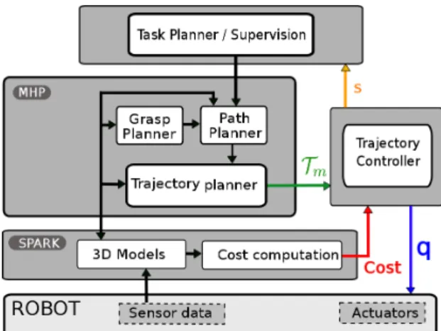
Fig. 1: Software Architecture of the robot for HRI manipulation.Tmis the main trajectory calcu-lated initially by MHP (Motion in Human Presence). The controller takes also cost maps from SPARK. The controller sends control signals in joint (q in the figure) to the servo system, and during the execution, the controller sends the state of the controller (s) to the supervisor
The robots capable of doing HRI must realize several tasks in parallel to manage various information sources and complete tasks of different levels. Figure 1 shows the proposed architecture where each component is implemented as a GENOM module. GENOM [14] is a development environment for complex real time embedded software. At the top level, a task planner and supervisor plans tasks and then supervises the execution. The module SPARK (Spatial Reasoning and Knowledge) maintains a 3D model of the whole environment, including objects, robots, posture and position of hu-mans [29]. It manages also the related geometrical reasoning of the 3D models, such as collision risk between the robot parts and between robot and environment. An im-portant element is that SPARK produces cost maps, which discribe a space distribution relatively to geometrical properties like human accesibility. The softwares for percep-tion, from which SPARK updates the 3D model of the environment, are omitted here for simplicity. The module runs at a frenquency of 20Hz, limited mainly by the complexity of the 3D vision and of the perception of human.
Another important module, MHP (Motion in Human Presence), integrates path and grasp planner. Rapidly exploring Random Tree (RRT) [24] and its variants are used by the path planner. The paths could be in Cartesian or joint spaces depending on the task type. From the path, an output trajectory is computed to take the time into account. MHP calculates a new trajectory each time the task planner defines a new task or when the supervisor decides that a new trajectory is needed for the changes of the environment.
The system should adapt its behavior to the dynamic environment, mainly the hu-man activities. But as the planning algorithms are time consuming, we introduce a tra-jectory controller that runs at 100 Hz, an intermediate frequency between the one of
the MHP planner and the one of the fast robot servo system. This trajectory controller allows the system to adapt faster the trajectory to the environment changes.
The main functionalities of the whole controller are:
– A decision process capable of integrating information form high-level software and building control primitives by segmenting the trajectory based on the HRI specifi-cations.
– Algorithms for target or trajectory tracking, trajectory switching, and coordinates transformation.
– A low-level collision checker and a monitor of the external torques for the safety issues.
1.2 Related Works
Reactive controller for object manipulation is a research topic that is part of the funda-mentals of robotic manipulation. Firstly, trajectory generation based approaches have been developed. In [7], results from visual system pass firstly through a low-pass filter. The object movement is modeled as a trajectory with constant acceleration, based on which, catching position and time is estimated. Then a quintic trajectory is calculated to catch the object, before being sent to a PID controller. The maximum values of acceler-ation and velocity are not checked when the trajectory is planned, so the robot gives up when the object moves too fast and the maximum velocity or acceleration exceeds the capacity of the servo controller. In [15], inverse kinematic functions are studied, catch-ing a movcatch-ing object is implemented as one application, a quintic trajectory is used for the robot manipulator to joint the closest point on the predicted object movement tra-jectory. The systems used in those works are all quite simple and no human is present in the workspace. A more recent work can be found in [19], in which a controller for visual servoing based on Online Trajectory Generation (OTG) is presented, and the results are promising.
Secondly, the research area of visual servoing provides also numerous results, a sur-vey of which were presented by Chaumette and Hutchinson [9], [10] and a comparison of different methods can be found in [13]. Classical visual servoing methods produce rather robust results and stability and robustness can be studied rigorously, but they are difficult to integrate with a path planner, and could have difficulties when the initial and final positions are distant.
Another approach to achieve reactive movements is through Learning from Demon-stration(LfD). In [8] and [31], points in the demonstrated trajectory are clustered, then a Hidden Markov Model(HMM) is built. Classification and reproduction of the trajecto-ries are then based on the HMM. A survey for this approach is proposed in [1]. Although LfD can produce the whole movement for objects manipulation, many problems may arise in a HRI context as LfD demands large set of data to learn, and the learned con-trol policies may have problem to cope with a dynamic and unpredictable environment where a service robot works.
Our approach to build the controller capable of controlling a complete manipula-tion tasks is based on Online Trajectory Generamanipula-tion. More results on trajectory gener-ation for robot control can be found in [22], [16], and [20]. The controller is capable
of dealing with various data in HRI context. Compared to methods mentioned above, approaches based on OTG have the following advantages:
– The integration with a path planner is easy and allows to comply with kinematic limits like the one given by human safety and comfort.
– The path to grasp a complex moving object is defined in the object frame, making sure that the grasping movement is collision free.
– The trajectory based method allows to create a simple standard interface for differ-ent visual and servo systems, easy plug-in modules can be created.
The controller integrates various information from high-level software. More informa-tion about human-aware moinforma-tion planning in the system can be found in [23]. More about geometrical reasoning can be found in [27], [24], and [28]. Physical Human Robot Interaction is a dynamic research area including various aspects, including safety, con-trol architecture, planning, human intention recognition, and more. Readers may refer to [12], [26], and [30] for more information of this promising research field.
2
Trajectory and control primitives
2.1 Online Trajectory Generation
Trajectories are time functions defined in geometrical spaces, mainly Cartesian space and joint space for robots. The books from Biagiotti [2] and the one from Kroger [17] summarize background materials. For detailed discussion about the trajectory generator used in the system, the reader can refer to [6] and [5], here we describe some results without further discussion.
Given a system in which position is defined by a set of coordinate X , a trajectory
T
is a function of time defined as:
T
: [tI,tF] −→ RN (1) t7−→T
(t) = X (t)The trajectory is defined from the time interval [tI,tF] to RNwhere N is the dimen-sion of the motion space. The trajectory
T
(t) can be a direct function of time or the compositionC
(s(t)) of a pathC
(s) and a function s(t) describing the time evolution along this path. The time evolution could be used in the controller to slow down or to accelerate when necessary [4].Our trajectory generator is capable of generating type V trajectories defined by Kroger [17] as satisfying:
X(tI) ∈ R X(tF) ∈ R |V (t)| 6 Vmax
V(tI) ∈ R V (tF) ∈ R |A(t)| 6 Amax (2)
A(tI) ∈ R A(tF) ∈ R |J(t)| 6 Jmax
Where X , V , A and J are respectively the position, the velocity, the acceleration and the jerk.
Fig. 2: Frames for object exchange manipulation: Fw: world frame; Fr: robot frame; Fc: camera frame; Fe: end effector frame; Fo: object frame; Fh: human frame. The trajectory realizing a manipulation should be controlled in different task frames.
1. The initial conditions (IC): X (tI) = XI, V (tI) = VIand A(tI) = AI; 2. The final conditions (FC): X (tf) = XF, V (tf) = VFand A(tf) = AF; 3. The continuity class of the trajectory is
C
2.4. The kinematics limits Vmax, Amaxand Jmax.
The problem is solved by a series of 3rddegree polynomial trajectories. Such a trajec-tory is composed of a vector of one-dimensional trajectories, which can be written as
T
(t) = (1Q(t),2Q(t), . . . ,NQ(t))Tfor joint motions orT
(t) = (1X(t),2X(t), . . . ,NX(t))T in Cartesian space.For the discussion of the next sections, we define Motion Condition as the position, velocity and acceleration at time t of the trajectory: M(t) = (X (t),V (t), A(t)). Once the trajectory is calculated, the function M(t) = getMotion(t,
T
) returns the Motion Condition on trajectoryT
at time t.2.2 Control Primitives
In HRI, the robot does various tasks like picking up an object, giving an object to human, taking an object from the human. For each of the task, a path is planned to realize it, and then the path is transformed into a trajectory. The controller designed here takes directly the trajectory as input and segments it based on the cost maps.
Figure 2 shows the basic frames needed to define a task. The trajectory
T
mdefines the move that allows the robot to do the task of grasping an object handed by the human.Based on the cost values associated to each point of the trajectory, the trajectory is divided into segments associated to a control strategy. The 3D cost maps used are of different types: collision risk map calculated based on the minimum distance between trajectory and the obstacles; visibility and reachability map of a human [27] and safety
and comfort 3D map of a human, Figure 3 shows two examples of cost maps. For example, when the risk of collision with the robot base is high, the trajectory can be controlled in robot the frame. Similarly, in the case where the human is handing an object to the robot, the grasping must be controlled in the object frame. [26] details other aspects of the use of cost maps to plan manipulation tasks.
Fig. 3: Left: 3D reachability map for a human. Green points have low cost, meaning that it is easier for the human to reach, while the red ones, having high cost, are difficult to reach. One application is that when the robot plans to give an object to a human, an exchange point must be planned in the green zone. Right: 3D visibility map. Based on visibility cost, the controller can suspend the execution if the human is not looking at the robot.
To simplify the presentation, in the reminder of the paper we focus on the manipu-lation tasks where a human hands over an object to the robot. During the manipumanipu-lations, the human moves and the different frames defining the task move accordingly. Based on the change of cost values, we divide the trajectory
T
min Figure 2 into three segments, as illustrated in the configuration space in the left part of Figure 7. In the figure, the points connecting the trajectory segments are depicted by red dots. The first segmentT
1, which is defined in the robot frame, has a high risk of auto-collision. When human or object moves, the cost value of collision risk stays the same. SegmentT
2has a lower collision cost value, so modifying the trajectory inside this zone does not introduce high collision risk. The end part, segment for grasping movementT
g, has a high collision cost value. To ensure the grasping succeeds without collision this segment of trajectory should be controlled in the moving object frame.We name task frame the frame in which the trajectory must be controlled. We define a control primitive
C P
by the combination of five elements: a segment of trajectory, a cost function, a task frame, a control mode, and a stop condition.C P
(t) = (T
seg(t),C
(t),F
,O
,S
)T (3) In which,T
seg(t) is the trajectory segment,C
(t) is the cost value associated to the trajectory which is monitored during the execution of a control primitive,F
is the task frame,O
is the control mode which we will define in next section, andS
is the stop condition of the control primitive. For example, the grasping movement includes five elements: the trajectory segmentT
g, the high collision risk cost valueC
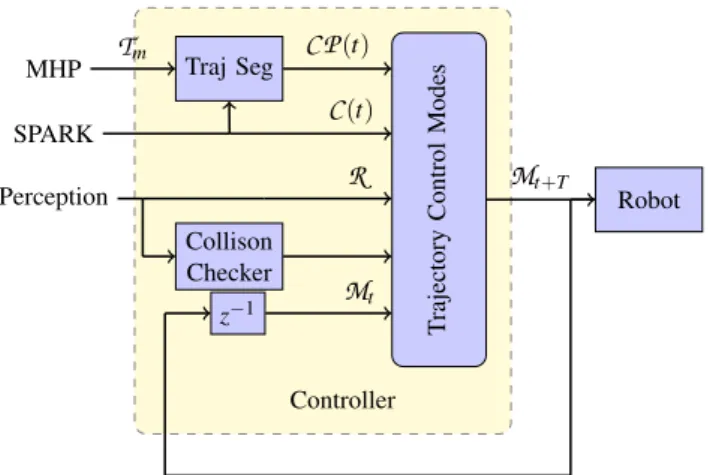
(t), theT rajectory Control M odes Traj Seg MHP Robot Collison Checker SPARK Perception C P(t) Tm R C(t) Controller Mt+T z−1 Mt
Fig. 4: Input and output of the controller.Tmis the trajectory computed by MHP, it is then seg-mented into control primitives (C P(t)). Traj Seg represents trajectory segmentation.C(t) are the cost values.R represents the tranformation matrices, giving the position of the target and of the robot.Mtis the current state of the robot,Mt+T is desired motion condition for the next control cycle. z−1represents delay of a control cycle.
task frame
F
o, the control mode as trajectery tracking, and the stop conditionS
as a predefined threshold for the distance between the robot end effector and the end point ofT
g. In the literature, Manipulation Primitives or Skill Primitives are often the concept for the intermediate level between planning and control and have been discussed in numerous works, as in [18].Using the definition of control primitives (
C P
(t)) and Motion Condition: M(t) = (X (t),V (t), A(t)), the different components of the trajectory controller and the input and output are presented in Figure 4. The initial trajectoryT
mis segmented into a series ofC P
(t). The cost valuesC
(t) are used during the segmentation, they are also mon-itored by the controller during execution of a control primitive. The collision checker integrates data from vision, human perception and encoder of the robot. It prevents col-lision risk by slowing down or suspending the task execution. With all the data and the current Motion ConditionM
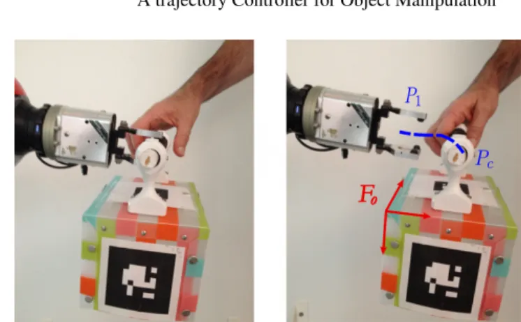
tof the robot, different control modes can compute Motion Condition for the next control cycle, which are the input for the robot sorvo system.Figure 5 shows the last control primitive of grasping an object. It is similar to the end part,
T
g, of the trajectory in Figure 2. The grasp position, the contact points and the final trajectory are planned by the grasp planner. More details on the grasp planner are given in [3] and [25]. When the object moves, the object frame Foand the path of the trajectory moves also. So to avoid collision, the trajectory of these control primitives must be controlled in the object frame Fo.3
Reactive Trajectory Control
At the control level, a task is defined by a series of control primitives, each defined by a quintuplet. The first level of the proposed trajectory controller is a state machine,
Fig. 5: A simple case of grasp. Left: a planned grasp defines contact points between the end effec-tor and the object. Right: To finish the grasping, the manipulaeffec-tor must follow the blue trajeceffec-tory P1- Pc, and then close the gripper. This movement must be controlled in the object frame Fo.
which controls the succession of the control modes, the collision managing and other special situations. Target tracking and trajectory tracking are parts of the control modes presented after the state machine.
3.1 Execution Monitoring
A state machine controls the switching between the different control modes associated to each control primitive and monitors the execution. Due to human presence, the robot environment is moving and the control task must be adapted accordingly. The state machine can also suspend or stop the control of a control primitive like depicted in Figure 6.
Suspend Events:When the visual system fails or the target becomes unavailable, or because of some specific human activities based on the monitoring of cost value
C
(t), the trajectory controller should suspend the task.Stop Events:Whatever the control mode chosen, unpredictable collisions can occur and they must stop the robot. Our controller uses two modules to detect these situations. The first one based on [11] monitors the external torques. The second is a geometric collision checker based on results from [21], it updates a 3D model of the workspace of the robot, and runs at the same frequency as the trajectory controller.
Slow Down On Trajectory:Based on the input cost function, the controller can slow down on the main trajectory by changing the time function s(t). Imagine that a fast movement could cause some people anxiety when the robot is close to them, for example. Details about this specific situation can be found in [4]. In this situation, the controller is still executing the task but only at a slower speed.
Each elementary controller based on online trajectory controller is implemented with a simple state machine inside.
Fig. 6: In the left, each circle represents the controller of a control primitive. The system can suspend or stop the execution of a control primitive.
obstacle obstacle obstacle obstacle Object v Object
Fig. 7: Left: trajectories of the control primitives. Right: trajectory switching for the controller due to the movement of an obstacle.
3.2 Trajectory Control Modes
Depending on the context defined by the control primitives, different control strategies must be developed. Online trajectory generator gives a flexible solution to build these controllers, which can easily react to unforeseen sensor events and adapt the kinematic parameters, mainly velocity, to the environment context. Switching to a new trajectory or a new frame in which the trajectory is controlled is also possible.
The main idea of the controller is to compute and follow a trajectory while joining up the target trajectory or a target point from the current state. Several control modes are defined to solve the reactive HRI manipulation problem.
Control Mode 1: Target tracking.If we suppose the robot is in an area without risk of collision, the system can track the end point of the trajectory. In this case, the controller generates iteratively a trajectory to reach the end point and send the first step of this trajectory to a low-level controller. In the special case where the controller does target tracking with visual system, it does visual servoing.
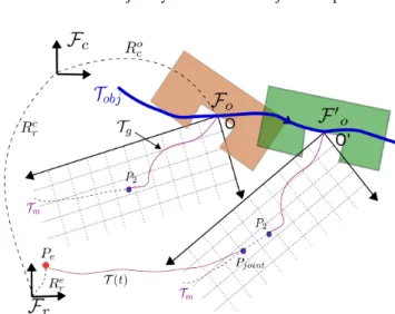
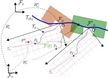
Figure 8 shows the details of the trajectory control mode for Target Tracking. The object is at position O at current time, and moves following the curve
T
ob j. This curveFig. 8: Control Mode 1. The robot tracks a point. The object moves to the right, it is drawn at two times: firstly in brown for time t1and then in green at time t2. In both cases, the entry point P2of the trajectoryTgis drawn relatively to the object frameFo.
is obtained by a simple Kalman filter, building a movement model from the results of 3D vision system.
F
r is the robot base frame,F
candF
oare camera frame and object frame, respectively. Also, Rcris the 4 × 4 transformation matrix from
F
rtoF
cand Rocthe transformation matrix fromF
ctoF
o. They are all in dashed line and they change with time when the humans or objects move. Initially, the robot is at point Pe, since there is no risk of collision, the controller can simply track point P2, which is the end point of the segment. It is also possible for the robot to join up the trajectory at another point Pjoint defined in the object frame which is the task frame. The details of the algorithm is given in Algorithm 1 where:T: duration of one control cycle.
Mr: current motion condition of the robot, so Mr= (Xr,Vr, Ar). δ: distance threshold to stop the tracking process.
Mg(t): motion conditions at time t on trajectory
T
g.MP2: motion conditions of the target P2on the main trajectory, which is calculated by
the planner.
MaxLoop: the maximum times the loop repeats for the controller to track the target or the trajectory. Once the time exceeds the value, the trajectory controller is sus-pended and a signal is sent to the supervisor, requiring the replanning of new task or a new path to realize the task.
X, Q: input signal in Cartesian space and in joint space for low-level controller.
Control Mode 2: Trajectory tracking in task frame.Once robot reaches point P2, it starts the grasping movement, which corresponds to
T
gin Figure 7. The object is still moving, but as the robot is in the high cost zone, it should track the main trajectory in the task frame. The details of the control mode is given in Algorithm 2.Figure 9 shows the details of the control mode, all the frames and object movements are the same as in Figure 8, but the robot is at point Pe0. The robot tracks
T
gin the frameF
o, and will end up executingT
0(t) in the robot frame.O
O'
Fig. 9: Control Mode 2. control mode. Object at time t1 is colored in light brown, and green at time t2. It follows a movement model given as the blue trajectoryTob j. The purple trajectory for graspingTgstays unchanged in the object frame. The robot tracks the trajectoryTgas it does th7e grasping movement.
Algorithm 1: Control for target tracking (Control Mode 1)
input : Target point P2;
while (distance(P2, Mr) > δ) ∧ (Loop < MaxLoop) do system time t = t + T , Loop = Loop + 1;
Update perception data;
if Collision Detected then Emergency stop; ;
if Suspend Events Occur then Suspend task; ;
Coordinates transformations;
Generate Type V control trajectoryT(t), for which: IC = Mr, FC = MP2; X= getMotion(t + T,T(t));
Inverse kinematics: X → Q; Qto the position servo system; end
Control Mode 3: Path re-planning and trajectory switch:during the execution, a path can be re-planned, for example when an obstacle moves (see Fig. 7). A new
trajec-Algorithm 2: Control for trajectory tracking in a moving work frame (Control Mode 2)
input : Trajectory segmentTg;
while (distance(Pc, Mr) > δ) ∧ (Loop < MaxLoop)) do system time t = t + T , Loop = Loop + 1;
Update perception data and object movement model; if Collision Detected then Emergency stop; ;
if Suspend Events Occur then Suspend task; ; Coordinates transformations; MTg= getMotion(t + T,Tg); Mob ject= getMotion((t + T,Tob j); X= MTg+ Mob ject; Inverse kinematics: X → Q; Qto the position servo system; end
tory is computed and given to the controller that switches to the new trajectory. While the controller is following the trajectory
T
m, an obstacle moves and invalidates the ini-tial trajectory. Then the system provides the controller with a new trajectoryT
0m begin-ning at time t1in the future. The controller anticipates the switch, and when the robot reaches Pt1 at time t1, the robot switches to the new trajectory
T
0
m. Because the new trajectory
T
0mis calculated using the state of the robot at time t1as its initial condition, the trajectory is switched without problem. The controller keeps the possibility of path re-planning. In some cases, a new path is needed to accomplish the task.
In this paper, we essentially solved the problem of the task of grasping a moving object held by the human counterpart. For other tasks, like picking an object, giving an object to human or putting an object on the table, the same functionalities can also be used. For example, putting an object on a moving platform would require the end segment of the main trajectory to be controlled in the frame of the platform, which moves in the robot frame. Likewise giving an object to a moving human hand will require the manipulator to track the exchange point, normally planned by a human-aware motion planner till the detection that human grasps the object successfully. Although a general algorithm to decompose the tasks into control primitives is still to develop, the basic HRI tasks can all be controlled by the control modes discussed above.
4
Manipulation Results
We focus on some results of how the controller is integrated in a HRI manipulator. For the performance of the trajectory generator, readers may refer to [6] and [4].
The controller has been implemented on the robot Jido at LAAS-CNRS. Jido is a mo-bile manipulator built up with a Neobotix momo-bile platform MP-L655 and a Kuka LWR-IV arm. Jido is equipped with one pair of stereo cameras and an ASUS Xtion depth sensor.
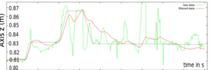
The software architecture that we used for Jido is presented in 1.1. Note that the pan-tilt stereo head may move during manipulations, then the transformation matrix from robot frame to camera frame is updated at the same frequency as the controller. The stereo-vision system uses marks glued on manipulated objects for localization. Unfortunately, the localization of these marks is highly sensible to lighting conditions and the esti-mated position of the object O in the robot frame
F
ris very noisy and unstable. Figure 10 shows the results returned by the 3D-vision system in poor lighting conditions and the result given by a Kalman filter. Even when raw data oscillates, this filter is capable to reduce the offset at the price of an acceptable delay. This reduces the oscillations of the robot arm too.Fig. 10: Instability of the 3D vision in poor lighting condition. The green curve shows axis z of the localization result of an object in the robot frame over 10 seconds and the red one shows the filtered result. The object was held by a human that intended to move the object accordingly to the black dashed curve.
Figure 11 shows the results of the target tracking by the trajectory controller, as in Case 2, over 25 seconds. For simplicity, only axis X is shown. The black dashed line is the position of the target, generated by the 3D vision system. The red line is the position of the robot. The two bottom diagrams show the velocity and acceleration of the robot in the same period. Firstly, we can see that the controller produces robust behavior to the noise in the visual system. Secondly, the velocity and acceleration of the robot are saturated as type V trajectories and calculated.
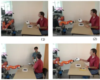
Finally, we show the behavior of the controller for a complete manipulation task. Figure 12 shows the scenario of the manipulation and Figure 13 shows the real position of the robot end effector in the robot frame (see figure 2 for the axes assignment of the robot base). The high-level task planner plans a task to receive the object. When the robot sees the object held by the human, the grasp planner calculates a valid grasp and the path planner with the trajectory generator plans the main trajectory for the robot to take the object.
The trajectory is divided into three segments by the controller, and different control modes are chosen. As we as seen above, each control primitive is associated to a tra-jectory segment. In this case, we obtain three segments, the first one is controlled in the robot frame, the second is defined as the tracking of the entry point of the third segment and the third segment is a trajectory defined in the object frame.
Fig. 11: Results of robot tracking a target: position (in m), velocity (in m/s) and acceleration (in m/s2) during the tracking for 25 seconds. The black dashed line is the target position, with noise of the 3D vision, and the red line is the position of the robot, which tracks the target with a delay. The positions of the robot are calculated from measured joint values and the kinematic model, while velocity and acceleration are estimated. The velocity, acceleration and jerk are always lim-ited, maintaining a smooth tracking process.
Fig. 12: (1): The controller is given the task of receiving the object from human. It tracks the first segment in the robot frame. (2): The object is moving and the robot tracks a target. (3): Human is distracted by another human and the task is suspended. (4): Human returns to the task, and the robot resumes the task and grasps the object.
During the target tracking, human is distracted because a second human arrives and gives an object to him. High-level software detects this event by monitoring the
time in s 0 20 40 60 Axis x in Axis y in Axi s z in 1.0 -0.2 0.0 0.6 10 30 50 0.2 0.4 0.6 0.8 0.4 0.2 0.0 0.2 0.4 (m) (m) (m) 0.8
Fig. 13: Real position of the robot arm end effector in the robot frame. The motion starts at time a; Between a and b: the controller tracks the first trajectory segmentT1inFr; From b to c and d to e: target tracking; From c to d: the task is suspended; From e to end: the grasping movement controlled inFo.
visibility cost map of the human. Because of the event, the controller suspends the task. It resumes the tracking when the human look again at the robot and the object to exchange come back in the reachable zone. Then, the grasping movement is finished. Note the performance of the target tracking process in the time intervals: between b to c, and between d to e. The controller finished the task reactively without the need of task or path replanning. The results shows that a reactive controller can be built based on Online Trajectory Generation, and as it is more responsive for the human, the robot is easier to interact with. Before the implementation of the reactive controller, the human needs to hold the object and stay still until the robot grasps it successfully.
5
Conclusion
A controller based on online trajectory generation has been presented with some results of robot grasping an object held by a human. The first results presented in the paper illustrate the versatility of the controller. In the example shown here, the controller switches between frames and suspends the control task when the human is distracted.
The trajectory controller employs different control modes for different situations. The control modes are all based on a trajectory generator. It is easy to use and to imple-ment and gives an efficient solution to follow trajectories and track moving objects in the HRI context. More precisely, it can adapt kinematic limits to the changing state of the scene and switch between trajectories and control modes.
The future work is to extend the trajectory controller to manage forces and to han-dle force events. Furthermore, the possibility to apply this type of trajectory control and the concept of control primitives to dual arm manipulations opens also interesting perspectives.
References
1. B. D. Argall, S. Chernova, M. Veloso, and B. Browning. A survey of robot learning from demonstration. Robotics and Autonomous Systems, 57(5):469 – 483, 2009.
2. L. Biagiotti and C. Melchiorri. Trajectory Planning for Automatic Machines and Robots. Springer, 2008.
3. B. Bounab, D. Sidobre, and A. Zaatri. Central axis approach for computing n-finger force-closure grasps. Proc. of the IEEE International Conference on Robotics and Automation, pages 1169–1174, May 2008.
4. X. Broqu`ere. Planification de trajectoire pour la manipulation d’objets et l’interaction Homme-robot. PhD thesis, LAAS-CNRS and Universit´e de Toulouse, Paul Sabatier, 2011. 5. X. Broqu`ere and D. Sidobre. From motion planning to trajectory control with bounded jerk
for service manipulator robots. In IEEE Intenational Conference of Robotics And Automa-tion, 2010.
6. X. Broqu`ere, D. Sidobre, and I. Herrera-Aguilar. Soft motion trajectory planner for service manipulator robot. Intelligent Robots and Systems, 2008. IROS 2008. IEEE/RSJ Interna-tional Conference on, pages 2808–2813, Sept. 2008.
7. G. Buttazzo, B. Allotta, and F. Fanizza. Mousebuster: A robot for real-time catching. IEEE Control Systems Magazine, 14(1), 1994.
8. S. Calinon and A. Billard. Stochastic gesture production and recognition model for a hu-manoid robot. In Intelligent Robots and Systems, 2004. (IROS 2004), volume 3, pages 2769 – 2774, sept. 2004.
9. F. Chaumette and S. Hutchinson. Visual servo control. part i: Basic approaches. IEEE Robotics and Automation Magazine, 4(13), December 2006.
10. F. Chaumette and S. Hutchinson. Visual servo control. part ii: Advanced approaches. IEEE Robotics and Automation Magazine, 1(14), March 2007.
11. A. De Luca and L. Ferrajoli. Exploiting robot redundancy in collision detection and reaction. In IROS 2008, pages 3299 –3305, sept. 2008.
12. A. De Santis, B. Siciliano, A. De Luca, and A. Bicchi. An atlas of physical human–robot interaction. Mechanism and Machine Theory, 43(3):253–270, 2008.
13. J.-S. Farrokh, D. Lingfeng, and J. William. Comparison of basic visual servoing methods. IEEE/ASME Transactions on Mechatronics, 16(5), October 2011.
14. S. Fleury, M. Herrb, and R. Chatila. Genom: A tool for the specification and the implemen-tation of operating modules in a distributed robot architecture. In IEEE/RSJ Int. Conf. on Intel. Rob. And Sys., 1997.
15. G. Gosselin, J. Cote, and D. Laurendeau. Inverse kinematic functions for approach and catching operations. IEEE Trans. Systems, Man, and Cybernetics, 23(3), 1993.
16. R. Haschke, E. Weitnauer, and H. Ritter. On-Line Planning of Time-Optimal, Jerk-Limited Trajectories. In IEEE/RSJ International Conference on Intelligent Robots and Systems, 2008. IROS 2008, pages 3248–3253, 2008.
17. T. Kr¨oger. On-Line Trajectory Generation in Robotic Systems, volume 58 of Springer Tracts in Advanced Robotics. Springer, Berlin, Heidelberg, Germany, first edition, jan 2010. 18. T. Kr¨oger, B. Finkemeyer, and F. Wahl. Manipulation Primitives A Universal Interface
be-tween Sensor-Based Motion Control and Robot Programming, volume 67 of Springer Tracts in Advanced Robotics. Springer Berlin Heidelberg, 2011.
19. T. Kr¨oger and J. Padial. Simple and Robust Visual Servo Control of Robot Arms Using an On-Line Trajectory Generator. IEEE International Conference on Robotics and Automation, 2012.
20. T. Kr¨oger, A. Tomiczek, and F. Wahl. Towards on-line trajectory computation. In Proceed-ings of the IEEE/RSJ International Conference on Intelligent Robots and Systems, Beijing, China. Citeseer, 2006.
21. E. Larsen, S. Gottschalk, M. Lin, and D. Manocha. Fast proximity queries with swept sphere volumes. 1999.
22. S. Liu. An on-line reference-trajectory generator for smooth motion of impulse-controlled industrial manipulators. In 7th International Workshop on Advanced Motion Control, pages 365–370, 2002.
23. J. Mainprice, E. Sisbot, L. Jaillet, J. Cort´es, T. Sim´eon, and R. Alami. Planning Human-aware motions using a sampling-based costmap planner. In IEEE Int. Conf. Robot. And Autom., 2011.
24. J. Mainprice, E. Sisbot, T. Sim´eon, and R. Alami. Planning Safe and Legible Hand-over Motions for Human-Robot Interaction. 2010.
25. J.-P. Saut and D. Sidobre. Efficient models for grasp planning with a multi-fingered hand. Robotics and Autonomous Systems, 60, March 2012.
26. D. Sidobre, X. Broqu`ere, J. Mainprice, E. Burattini, A. Finzi, S. Rossi, and M. Staffa. Human–robot interaction. Advanced Bimanual Manipulation, pages 123–172, 2012. 27. E. Sisbot, R. Ros, and R. Alami. Situation assessment for human-robot interactive object
manipulation. 20th IEEE International Symposium on Robot and Human Interactive Com-munication, July-August 2011.
28. E. A. Sisbot, L. F. Marin-Urias, R. Alami, and T. Sim´eon. Spatial reasoning for human-robot interaction. In IEEE/RSJ Int. Conf. on Intel. Rob. And Sys., San Diego, CA, USA, November 2007.
29. E. A. Sisbot, L. F. M. Urias, R. Alami, and T. Sim´eon. Spatial reasoning for human-robot interaction. In IEEE/RSJ International Conference on Intelligent Robots and Systems, IROS, San Diego, CA, USA, November 2007.
30. K. W. Strabala, M. K. Lee, A. D. Dragan, J. L. Forlizzi, S. Srinivasa, M. Cakmak, and V. Micelli. Towards seamless human-robot handovers. Journal of Human-Robot Interac-tion, 2(1):112–132, 2013.
31. A. Vakanski, I. Mantegh, A. Irish, and F. Janabi-Sharifi. Trajectory learning for robot pro-gramming by demonstration using hidden markov model and dynamic time warping. Sys-tems, Man, and Cybernetics, Part B: Cybernetics, IEEE Transactions on, 42(4):1039 –1052, aug. 2012.