Design, Modeling, Fabrication, and Testing of a
Piezoelectric Microvalve for High Pressure, High
Frequency Hydraulic Applications
by
David C. Roberts S.B., Mechanical Engineering Massachusetts Institute of Technology, 1995
S.M., Mechanical Engineering
Massachusetts Institute of Technology, 1998
SUBMITTED TO THE DEPARTMENT OF MECHANICAL ENGINEERING IN PARTIAL FULFILLMENT OF THE DEGREE OF
DOCTORATE OF PHILOSOPHY at the
MASSACHUSETTS INSTITUTE OF TECHNOLOGY
February 2002
© 2002 Massachusetts Institute of Technology
All rights reserved
BARKER
MASSACHUSETTS IN TITUTE OF TECHNOLOGYMAR 2 5 2002
LIBRARIES
Signature of A uthor ...Department of Mechanical Engineering
Certified by Doctoral Committee January 10, 2002
Nesbitt W. Hagood (Co-Chair), Associate Professor of Aeronatips and Astronautics
. . .. . . ... Martin A. Schmidt
Professor of Electrical Engineering
.... . . ... .. .. .. .... F
---David L. Trumper (Co-Chair), Associate Professor of Mechanical Engineering
"'S. Mark SpeariffgXAssociate Professor of Aeronautics and Astronautics
A ccepted by ... _
Professor Ain Sonin Chairman, Department Graduate Committee
Design, Modeling, Fabrication, and Testing of a Piezoelectric Microvalve for
High Pressure, High Frequency Hydraulic Applications
by
David C. Roberts
Submitted to the Department of Mechanical Engineering on January 10, 2002, in partial fulfillment of the requirements for the Degree of Doctor of Philosophy in Mechanical Engineering.
Abstract
A piezoelectrically-driven hydraulic amplification microvalve for use in high specific power hydraulic
pumping applications was designed, fabricated, and experimentally characterized. High frequency, high force actuation capabilities were enabled through the incorporation of one or more bulk piezoelectric material elements beneath a micromachined annular tethered-piston structure. An hydraulic ampli-fication mechanism was employed to amplify the limited stroke of this piezoelectrically-driven piston structure to a significantly larger motion (40-50x) of a micromachined valve membrane with attached valve cap. This valve cap was actuated through its stroke to open and close against a fluid orifice. These design features enabled the valve device to simultaneously meet a set of high frequency (1-10kHz), high pressure(0.1-1MPa), and large stroke (15-40pm) requirements that had not previously been satisfied by other microvalves presented in the literature.
This research was carried out through a series of modeling, design, fabrication, assembly, and experi-mental testing tasks. Linear and non-linear modeling tools characterizing the structural deformations of the active valve sub-systems were developed. These tools enabled accurate prediction of real-time stresses along the micromachined valve membrane structure during deflection into its non-linear large-deflection regime. A systematic design procedure was developed to generate an active valve geometry to satisfy membrane stress limitations and valve power consumption requirements set forth by external hydraulic system performance goals. Fabrication challenges, such as deep-reactive ion etching (DRIE) of the drive element and valve membrane structures, wafer-level silicon-to-silicon fusion bonding and silicon-to-glass anodic bonding operations, preparation and integration of piezoelectric material elements within the micromachined tethered piston structure, die-level assembly and bonding of silicon and glass dies, and filling of degassed fluid within the hydraulic amplification chamber were overcome.
The active valve structural behavior and flow regulation capabilities were evaluated over a range of applied piezoelectric voltages, actuation frequencies, and differential pressures across the valve. For applied piezoelectric voltages up to 500Vpp at
1kHz,
the valve devices demonstrated amplification ratios of drive element deflection to valve cap deflection of 40-50x. These amplification ratios correlated within5 - 10% of the model expectations. Flow regulation experiments proved that a peak average flow rate
through the device of 0.21mL/s under a 1kHz sinusoidal drive voltage of 500Vpp, with valve opening of 17pm, against a differential pressure of 260kPa could be obtained. Tests revealed that fluid-structural interactions between the valve cap and membrane components and flow instabilities (due to transition between the laminar and turbulent flow regimes through the valve orifice) limited the valve performance capabilities.
Thesis Supervisor: Dr. Nesbitt W. Hagood
Acknowledgements
This research work was sponsored by DARPA under Grant #DAAG55-98-1-0361 and by ONR under Grant #N00014-97-1-0880.
The research presented in this thesis could not have been accomplished without the generous support and hard work of a large group of individuals. First and foremost, I would like to thank my advisor, Dr. Nesbitt Hagood, for providing the programmatic resources and support for this research, as well as the numerous opportunities to present this work within the MIT community and at academic conferences. Additionally, his ability to always be one step ahead of the game kept me sharp and forced me to defend and clearly justify all of the decisions made along the path of my PhD work. I would also like to acknowledge my doctoral committee members, Dr. Martin Schmidt, Dr. Mark Spearing, and Dr. David Trumper, for their advice and direction during this work. These interactions have helped me to mature, both intellectually and personally. Additionally, I would like to acknowledge Dr. Kenneth Breuer, at Brown University, for his very helpful guidance on microscale fluid related issues.
I owe a great deal of thanks to Dr. Richard Mlcak, at Boston Microsystems, Inc, for his introduction to the world of MEMS, through initial piezoelectric material integration studies at the onset of the MHT research program four years ago and his continued support in the area of microscale fluid filling and sealing. Additionally, instrumental to the accomplishments embodied within this work were Dr. Laxman Saggere, for his advice on modeling assumptions within my active valve optimization code; Kevin Turner, for his contributions in the area of eutectic bonding; Blair Connelly, for her hard work in the development of testing apparatus for use with the laser vibrometer system used in this work; David Robertson, for his lab organization and debugging activities; Tim Glenn, for his generous support in providing exceptional renderings of MEMS devices for the MHT program; and Seward (Chip) Pulitzer, for his initial system modeling work at the beginning of the program.
Jorge Carretero and Onnik Yaglioglu have been sources of continual support in the development of fluid flow models and full system-level simulations for this active valve device and for MHT sys-tems, in general. Dr. Yu-Hsuan Su was essential to the development of the finite-difference numerical modeling scheme, which serves as the backbone of the non-linear large deflection valve membrane code presented in Chapter 2 of this thesis. Dr. Hanqing Li deserves an unbelievable amount of recognition for his dedication in and out of the cleanroom, providing the MHT program with repeatable and robust fabrication processes for the creation of etched silicon wafers and silicon-glass bonded stacks. Lastly, from the programmatic side of things, I have to give a great deal of thanks to Lodewyk Steyn, who throughout his time on the MHT program, has performed duties above and beyond what were required of him in an effort to unselfishly move the program forward. Without his dedication, especially on the experimental testing side of the program, the validation of fluid-filled active valve devices would not have been accomplished in such an aggressive time frame.
Finally, I would like to thank my family. None of this work could have been accomplished without the positive support from my Mom, Dad, and brother Will. Most importantly, I have to thank my wife, Heather, for her unbelievable support and patience through four and half years of sometimes frustrating, sometimes exhilarating, and all the time stressful research work.
Contents
1 Introduction 1.1 Motivation 1.2 1.3 1.4 1.5 1.6 1.7 25 . . . . 2 5Overview of Previous Microvalve Technology . . . .
Concept . . . . Challenges . . . . 1.4.1 Modeling and Design Challenges . . . . 1.4.2 Device Fabrication, Assembly, and Testing Challenges Objectives . . . . Approach . . . . Thesis Executive Summary . . . . 2 Active Valve Linear Model
2.1 Valve Geometry and Modeling Procedure . . . .
2.2 Overview of Linear Plate Theory . . . . 2.2.1 Deflections Due to Bending . . . . 2.2.2 Deflections Due to Shearing . . . .
2.2.3 Combined Deflection Due to Bending and Shearing 2.2.4 Comparison of Bending/Shearing Deflections . . . 2.3 Detailed Structural Modeling . . . .
2.3.1 Piezoelectric Material Behavior . . . .
2.3.2 Drive Element Piston and Tether Behavior . . . . 2.3.3 Bottom Structural Compliance . . . .
2.3.4 Fluid Compressibility . . . .
2.3.5 Top Structural Compliance . . . .
2.3.6 Valve Cap and Membrane Behavior . . . .
2.4 Full Active Valve Linear Model . . . .
2.5 Impact of Multiple Piezoelectric Cylinders . . . .
2.5.1 Finite-Element Analysis of Piston . . . .
. . . . 28 . . . . 33 . . . 35 . . . 36 . . . 37 . . . . 39 . . . . 39 . . . 41 47 . . . 47 . . . 48 . . . 49 . . . 50 . . . . 5 1 . . . . 5 1 . . . 5 2 . . . 5 2 . . . 53 . . . 57 . . . 5 8 . . . 58 . . . 5 9 . . . . 6 1 . . . . 6 2 . . . 6 2
2.5.2 Finite-Element Analysis of Bottom Plate . . . 65
2.6 Further Modeling Issues . . . . 66
2.7 Conclusions . . . 67
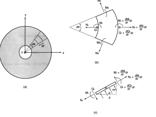
3 Non-Linear Deformation of the Valve Cap and Membrane 69 3.1 Introduction . . . 69 3.2 Plate Geometry . . . 70 3.3 T heory . . . 70 3.3.1 Assumptions . . . . 70 3.3.2 Equilibrium Equations . . . 71 3.3.3 Geometric Compatibilities . . . . 72 3.3.4 Constitutive Laws . . . 73 3.3.5 Governing Equations . . . 73 3.3.6 In-Plane Prestress . . . . 74
3.3.7 Non-Dimensionalized Governing Equations . . . . 76
3.3.8 Finite-Difference Implementation . . . . 78
3.3.9 Post-Processing Calculations . . . 81
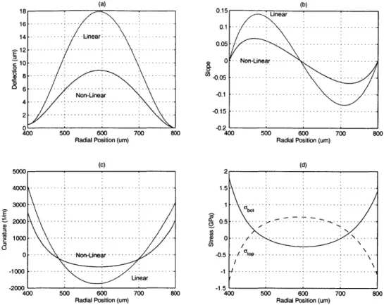
3.4 Results of Numerical Code . . . 83
3.4.1 Loading: Pi = P2 = 0, P3 = 100kPa, N = 0 . . . 84
3.4.2 Loading: P1 = 2.90MPa, P2 = 0, P3 = 1.30MPa, N = 0 . . . 84
3.4.3 Loading: P1 = P2 = 0, Varying P3, N, = 0 . . . 85
3.4.4 Loading: Pi P2 = 0, PHAC = 100kPa, Varying N . . . .. 86
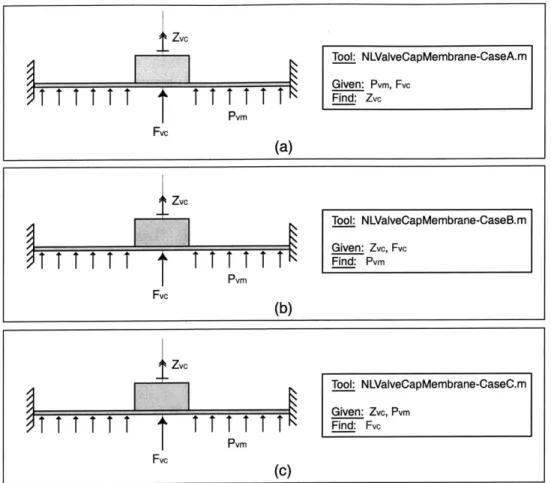
3.5 Matlab Non-Linear Tools . . . 87
3.6 C onclusions . . . 89
4 Active Valve Non-Linear Model and Simulation 91 4.1 Quasi-Static Active Valve Model . . . . 91
4.2 Accuracy of Quasi-Static Model . . . 93
4.2.1 Assumptions in Model . . . 93
4.2.2 FEM Model Geometries and Correlation Procedure . . . 94
4.2.3 Model Correlation Procedure . . . 95
4.2.4 Valve Geometry . . . . 96
4.2.5 Model Correlation . . . 97
4.3 Finite-Element Resonant Behavior . . . 101
4.4 Dynamic Active Valve Simulation . . . 102
4.4.1 Linear Matrix Relations . . . 102
4.4.2 Non-Linear Look-Up Tables . . . 103
4.5 Conclusions . . . 106
5 Active Valve Design Procedure
5.1 Valve Requirements in Generic MHT System . . . . 5.2 Modeling of External Hydraulic System . . . . 5.2.1 MHT Chamber Stiffness . . . . 5.2.2 Valve Channel Inertial Effects . . . .
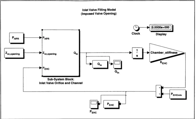
5.2.3 Valve Orifice Flow Relations . . . .
5.2.4 Chamber Filling Simulation Tool . . . .
5.3 Systematic Design Procedure . . . .
5.3.1 Overview . . . .
5.3.2 System Requirements . . . . 5.3.3 Step 1: Design of Valve Cap . . . . 5.3.4 Step 2: Design of Valve Membrane . . . .
5.3.5 Step 3: Design of Piezoelectric Drive Element 5.4 Design Freedoms Within Procedure . . . .
5.4.1 Design Freedom: ZvC,stroke . . . . . .. 5.4.2 Design Freedom: tm. . . .. 5.5 Power Consumption in Active Valve . . . .
5.5.1 Overview of Energy/Power Consumption . . 5.5.2 Benefit of Multiple Valve Heads . . . .
5.6 Results of Systematic Design Procedure . . . .
5.7 Correlation With Dynamic Simulation . . . .
5.8 Conclusions . . . .
6 Device Fabrication and Preparation for Testing 6.1 Introduction . . . .
6.2 Fabrication Challenges and Procedures . . . .
6.2.1 Etching of Tethered Drive Element and Valve
6.2.2 Wafer-Level Bonding . . . .
6.2.3 Integration of Bulk Piezoelectric Elements . .
6.2.4 Die-Level Assembly and Bonding . . . .
6.2.5 Fluid Filling/Sealing of HAC . . . . 6.3 Sub-Component Testing Plan . . . .
6.3.1 Piezoelectric Drive Element . . . .
6.3.2 Valve Cap and Membrane . . . . 6.3.3 Full Active Valve . . . .
6.4 Testing Apparatus . . . . 109 110 .111 112 113 113 116 118 118 119 119 121 122 125 125 126 134 134 135 138 142 145 147 . . . 14 7 . . . 14 8 Membranes . . . 149 . . . 15 1 . . . 152 . . . 157 . . . 16 1 . . . 165 . . . 165 . . . 166 . . . 16 7 . . . 167
6.4.1 Laser Vibrometer System . . . .
6.4.2 Fluids Test-Rig . . . 168
6.5 Conclusions . . . 168
7 Sub-Component Study: Piezoelectric Drive Element 173 7.1 Objectives . . . 173 7.2 Device Test-Plan . . . 174 7.2.1 1st Generation Devices . . . 174 7.2.2 2nd Generation Device . . . 176 7.3 Device Assembly . . . 177 7.4 Testing Procedure . . . 180 7.5 Experimental Results . . . 180 7.5.1 1st Generation Devices . . . 180 7.5.2 2nd Generation Device . . . 196 7.6 Conclusions . . . 200
8 Sub-Component Study: Valve Cap and Membrane 203 8.1 Objectives . . . 203 8.2 Device Test-Plan . . . 204 8.2.1 Geometry . . . 204 8.2.2 Device Assembly . . . 205 8.2.3 Testing Procedure . . . 205 8.3 Theoretical Predictions . . . 206
8.3.1 1st Modeling Procedure: Numerical Non-linear Deflection Code . . . 206
8.3.2 2nd Modeling Procedure: Finite-element Code . . . 207
8.4 Experimental Results . . . 213
8.4.1 Fillet Radius Inspection . . . 213
8.4.2 Pressure-Deflection Results . . . 213
8.5 Conclusions . . . 214
9 Active Valve Testing 217 9.1 Objectives . . . 217
9.2 Device Test-Plan . . . 218
9.2.1 Geometry . . . 218
9.2.2 Plan of Study . . . 218
9.3 Experimental Testing Section 1: Active Valve Structural Performance . . . 220
9.3.1 Testing Section 1: Active Valve Structural Performance . . . 220
9.3.2 Testing Section 2: Active Valve Fluid Flow Regulation . . . 252
9.4 Conclusions . . . . 10 Conclusions and Recommendations
10.1 Summary and Conclusions ...
10.1.1 Thesis Summary . . . .
10.1.2 Thesis Contributions . . . . 10.2 Recommended Further Work and the Future of MHTs . . . . . 10.2.1 Redesign for Enhanced Operational Frequency . . . . . 10.2.2 Understanding of Flow Induced Structural Instabilities .
10.2.3 Materials Characterization . . . .
10.2.4 Microfabrication Issues . . . .
10.2.5 Future of MHTs . . . .
. . . 276
A Support Documentation for Active Valve Linear Model
A.1 ChapterExample.mws . . . . A.2 FullActiveValve(LINEAR).mws [see Section 2.4] . . . .
B Support Documentation for Non-Linear Valve Cap/Membrane
B.1 NLValveCapMembrane-CaseA.m [see Section 3.5] . . . . B.2 NLValveCapMembrane-CaseB.m [see Section 3.5] . . . . B.3 NLValveCapMembrane-CaseC.m [see Section 3.5] . . . .
279 279 279 284 285 286 287 290 291 292 295 296 299 313 314 318 322
C Support Documentation for Full Non-Linear Active Valve Model C.1 FullActiveValve(Non-Linear).mws [Section 4.1] . . . . C.2 NLActiveValveMatlab.m [Section 4.1] . . . .
327
. . . 328 . . . 334
List of Figures
1.1 Upper bound on specific work vs. frequency for various actuation media . . . . . 1.2 Generic block diagrams of Micro-Hydraulic Transducer systems . . . .
1.3 Selected thermal, electrostatic, and electromagnetic microvalves previously re-ported in the literature . . . . 1.4 Selected piezoelectrically-driven microvalves previously reported in the literature
1.5 3-D schematic of the piezoelectrically driven hydraulic amplification microvalve 1.6 Schematic of the fabricated multi-layer active valve structure . . . .
1.7 Schematic of fabricated multi-layer MHT actuator device . . . . 1.8 Active valve sub-component fabrication and testing plan . . . .
1.9 Photograph of a 9-layer piezoelectrically-driven hydraulic amplification microvalve. 2.1 2-D schematic of the piezoelectrically-driven hydraulic amplification microvalve. .
Linear plate theory for a generic circular plate. . . . . Bending and shearing contributions to plate deformation . . Modeling of the piezoelectric material element . . . . Modeling of the drive element tethered piston structure . .
Modeling of the bottom structural plate . . . . Modeling of the top structural plate . . . . Linear modeling of the valve cap and membrane structure . Simplified schematic of the valve membrane structure . . .
Blow-up view of the modeled components in the microvalve Finite-element schematics of the drive element piston . . . .
. . . 49 . . . . 52 . . . 53 . . . 54 . . . 58 . . . 59 . . . 59 . . . 60 . . . . 6 1 . . . 63 2.12 Compliance coefficients for the drive element piston with multiple piezoelectric
cylinders... ...
2.13 Finite-element schematics of the bottom plate structure . . . .
2.14 Compliance coefficients of the bottom plate structure with multiple piezoelectric cylinders... ...
3.1 Simplified schematic of the valve membrane structure . . . . 27 28 29 31 34 36 37 41 42 48 2.2 2.3 2.4 2.5 2.6 2.7 2.8 2.9 2.10 2.11 64 65 66 70
3.2 3.3 3.4 3.5 3.6 3.7 3.8 3.9 3.10 4.1 4.2 4.3 4.4 4.5 4.6 4.7 4.8 4.9 4.10 4.11 5.1 5.2 5.3 5.4 5.5 5.6 5.7 5.8 5.9 5.10 5.11 5.12 5.13 5.14 5.15 5.16 . . . 71 . . . 75 . . . 79 . . . 83 . . . 84 . . . 86 . . . 87 . . . 88 . . . 89
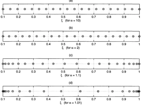
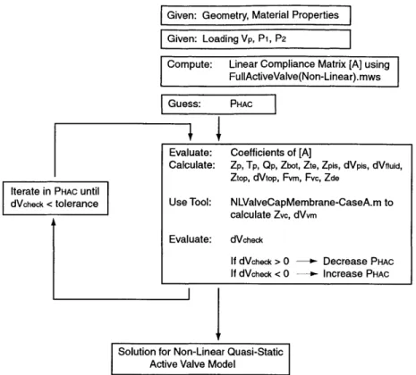
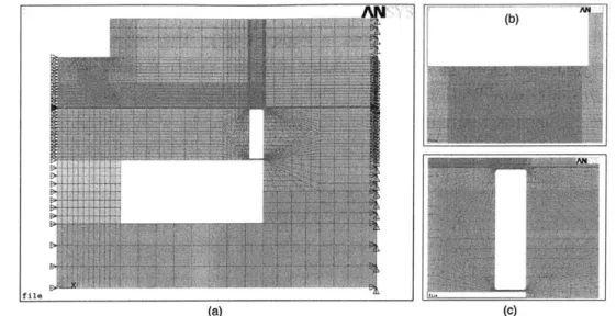
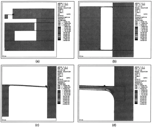
Boundary conditions imposed in the active valve finite-element models Monitored variables in the active valve models . . . . Finite-element stresses predicted in the active valve device . . . . Finite-element modal behavior of the active valve . . . . Dynamic simulation architecture of the active valve . . . . Look-up tables describing valve membrane large deflection behavior Piston dynamics included in the simulation . . . . Valve cap dynamics included in the simulation . . . . Schematic of a generic MHT power harvesting device . . . . Filling/evacuation of the harvesting chamber through the valves . . . Modeling of the valve orifice . . . . Look-up tables for valve orifice coefficients . . . . Simulation architecture for chamber filling through active valve . . . . Simulation architecture for active valve orifice and channel . . . . Force and moment diagrams for a plate section . . . . Schematic of a pretensioned annular plate . . . . Coordinate transformation used within numerical code . . . Pressure loading terminology on an annular plate . . . . Deflection of a thin annular plate under loading scenario 1 Deflection of a thin annular plate under loading scenario 2 Deflection of a thin annular plate under loading scenario 3 Deflection of a thin annular plate under loading scenario 4 Numerical code tools to be used throughout thesis . . . . . Quasi-static non-linear active valve model overview . . . . . Finite-element model of the active valve without fillet radii Finit-lement mrdel nf fhe ati-ive alue it-h fiet11o rnaii Flowchart for the quasi-static systematic active valve design procedure . . . 118
Chamber filling as a function of valve cap radius . . . 120
Design plots for the valve membrane . . . 121
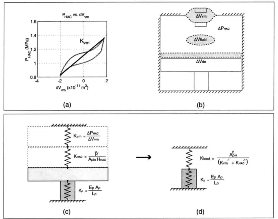
Modeling of the active valve structure in an impedance match condition . . . 123
Drive element behavior design plots . . . 124
Valve cap size vs. imposed valve cap stroke . . . 126
Valve membrane size and thickness vs. imposed valve cap stroke: Case 1 . . . 127
Maximum valve membrane stress vs. membrane radius: Case 1 . . . 128
Example valve membrane deflection plots: Case 1 . . . 129
Valve membrane size and thickness vs. imposed valve cap stroke: Case 2 . . . 130
. . . 92 . . . 94 . . . 95 . . . 96 . . . 97 . . . 100 . . . 102 . . . 103 . . . 104 . . . 105 . . . 105 . . . 110 . . . 112 . . . 113 . . . 115 . . . 117 . . . 117
5.17 5.18 5.19 5.20 5.21 5.22 5.23 5.24 6.1 6.2 6.3 6.4 6.5 6.6
Maximum valve membrane stress vs. membrane radius: Case 2 . . . 131
Example valve membrane deflection plots: Case 2 . . . 133
Hysteretic energy loss in active valve . . . 134
Full quasi-static design procedure results: Part 1 . . . 139
Full quasi-static design procedure results: Part 2 . . . 140
Full quasi-static design procedure results: Part 3 . . . 141
Simulation architecture for the filling/evacuation of the MHT system . . . 143
System simulation plots using the designed active valve geometry . . . 144
Schematic cross-section of a multi-layer MHT/active valve structure . . . 148
DRIE etch characteristics of a drive element piston and tether . . . 149
SEM etch images of a drive element piston and tether . . . 150
Wafer-level silicon-silicon fusion and silicon-pyrex anodic bond steps . . . 151
Piezoelectric material surface roughness scans . . . 153
Piezoelectric thin-film eutectic alloy composition . . . 154
6.7 Precision micrometer measurement of a piezoelectric element thickness . . . 155
6.8 Piezoelectric element tolerancing within drive element structure . . . .. 156
6.9 Die-level bonding procedure for active valve device . . . 158
6.10 Die-level alignment and bonding jigs . . . 160
6.11 Electrical contact to an active valve chip for anodic bonding . . . 160
6.12 Fluid filling apparatus to fill active valve devices . . . 161
6.13 Fluid filling schematic of component connections . . . 162
6.14 Schematic of the high resistance fluid channel between the HAC and an external bias pressure . . . 163
6.15 Model of the high resistance fluid channel between the HAC and an external bias pressure ... ... ... ... 164 6.16 6.17 6.18 6.19 7.1 7.2 7.3 7.4 7.5 7.6 7.7 Active valve sub-component fabrication and testing plan . . . 165
Drive element sub-component test structures . . . 166
Valve membrane sub-component study and full active valve study . . . 167
Fluids test-rig for testing of the active valve and its sub-components . . . 169
3-D schematic of a piezoelectric drive element device . . . 174
Overview of the drive element sub-component test plan . . . 175
Drive element geometries and piezoelectric element layout . . . 176
Exploded view of drive element structure . . . 177
Assembly of a piezoelectric drive element device . . . 178
Photographs of fabricated 1st-generation drive element device . . . 179
7.8 Measurement points on drive element piston surface using scanning laser vibrometer 181
7.9 Inspection of fillet radii on
1st-generation
devices . . . 1827.10 Piezoelectric material characterization of representative elements . . . 183
7.11 Device 1 transfer functions of piston velocity versus frequency . . . 185
7.12 Device 1 modal behavior . . . 186
7.13 Vibrometer scan images of Device 1 low-frequency 15kHz displacement profile . . 186
7.14 Device 1 displacement time histories for a sinusoidal drive voltage of 500V±500V at f = 15kH z . . . 187
7.15 Device 1 displacement time histories for a sinusoidal drive voltage of 500V±500V at f = 7kH z . . . .187
7.16 Device 1 piston center displacement versus applied voltage at 100Hz . . . 187
7.17 Device 2 transfer functions of piston velocity versus frequency . . . 189
7.18 Device 2 modal behavior . . . 190
7.19 Vibrometer scan images of Device 2 low-frequency 15kHz displacement profile . . 190
7.20 Device 2 displacement time histories for a sinusoidal drive voltage of 500V±500V at f = 15kH z . . . 191
7.21 Device 2 displacement time histories for a sinusoidal drive voltage of 500V±500V at
f
= 7kH z . . . 1917.22 Device 2 piston center displacement versus applied voltage at 100Hz . . . 191
7.23 Device 3 transfer functions of piston velocity versus frequency . . . 193
7.24 Vibrometer scan images of selected Device 4 modal behavior . . . 194
7.25 Device 3 ANSYS finite-element model prediction for 1st mode . . . 194
7.26 Vibrometer scan images of Device 3 low-frequency 15kHz displacement profile . . 194
7.27 Device 3 displacement time histories for a sinusoidal drive voltage of 500V±500V at
f
= 15kH z . . . 1957.28 Device 3 displacement time histories for a sinusoidal drive voltage of 500V±500V at f = 7kH z . . . 195
7.29 Device 3 piston center displacement versus applied voltage at 100Hz . . . 195
7.30 Device 4 transfer functions of piston velocity versus frequency . . . 197
7.31 Vibrometer scan images of selected Device 4 modal behavior . . . 198
7.32 Vibrometer scan images of Device 4 low-frequency 15kHz displacement profile . . 198
7.33 Device 4 displacement time histories for a sinusoidal drive voltage 500V±500V at
f
= 15kH z . . . 1997.34 Device 4 piston center displacement versus applied voltage at 100Hz . . . 199
8.1 2-D schematic of a valve cap and membrane structure . . . 204
8.3 Valve cap and membrane sub-component structure . . . 205 8.4 Baseline valve cap and membrane design dimensions . . . 209
8.5 Sensitivity of baseline valve cap and membrane design to variations in valve membrane thickness . . . 210
8.6 Finite-element mesh of valve cap and membrane structure . . . 211
8.7 Finite-element stress contours resulting from applied differential pressure loading 211
8.8 Sensitivity of baseline valve cap and membrane design to variations in fillet radius
size . . . .. . 212 8.9 Valve cap and membrane experimental pressure-deflection results . . . 214
9.1 Dimensions of active valve devices AV1 and AV2 . . . 219
9.2 Device AV1 low-voltage valve cap frequency response from 500Hz to 100kHz, with and without oil present above the valve structure. . . . 223
9.3 Device AV1 low-voltage piston and valve cap frequency responses from 500Hz to 100kHz, with oil present above the valve structure. . . . 224 9.4 Device AV1 low-voltage valve cap frequency responses from 500Hz to 100kHz,
for varying Pbias... . . . . . . . . . . . . . . . 225 9.5 Device AVI low-voltage valve cap frequency responses from 500Hz to 100kHz,
for varying differential pressure applied to valve cap and membrane structure. . 226 9.6 Device AV1 valve cap frequency responses from 500Hz to 3kHz, for Pias =
500kPa and increasing high voltage drive levels. . . . 227 9.7 Device AVI high-voltage piston and valve cap frequency responses from 500Hz
to 3kHz, for Pbias = 500kPa. . . . 228
9.8 Device AVI valve cap and piston deflection time histories for 1kHz sinusoidal drive voltage levels. . . . 230
9.9 Device AVI valve cap peak-peak motion, piston peak-peak motion, and device amplification ratio as a function of 1kHz sinusoidal drive voltage levels. . . . 231 9.10 Device AV1 valve cap peak-peak motion, piston peak-peak motion, and device
amplification ratio as a function of 1kHz sinusoidal drive voltage levels, with Pvc,vm = 50kP a. . . . 232 9.11 Experimental verification of the high-frequency channel in device AVI. . . . 233 9.12 Device AV2 low-voltage valve cap frequency response from 500Hz to 100kHz,
with and without oil present above the valve structure. . . . 236
9.13 Device AV2 low-voltage valve cap frequency responses from 500Hz to 100kHz,
for varying Pbias.. . . . .. . . . .. .. - . . . . . . 237
9.14 Device AV2 valve cap frequency responses from 500Hz to 3kHz, for Pbias = 500kPa and increasing high voltage drive levels. . . . 238
9.15 Device AV2 high-voltage piston and valve cap frequency responses from 500Hz
to 3kHz, for Pias = 500kPa. . . . 239
9.16 Device AV2 valve cap and piston deflection time histories for 1kHz sinusoidal
drive voltage levels. . . . 240
9.17 Device AV2 valve cap peak-peak motion, piston peak-peak motion, and device
amplification ratio as a function of 1kHz sinusoidal drive voltage levels. . . . 241 9.18 Device AV1 and device AV2 quasi-static 1kHz model correlation for fluid bulk
modulus Kf = 2.OGPa. . . . 244
9.19 Device AVI and device AV2 quasi-static 1kHz model correlation for varying fluid
bulk m odulus K f. . . . 245 9.20 Finite-element active valve modal frequency sensitivity studies . . . 248 9.21 Finite-element modal frequency sensitivity to valve cap added mass . . . 251 9.22 Model correlation to device AV1 quasi-static fluid flow rate versus valve opening
behavior for differing imposed differential pressures . . . 253
9.23 Schematic of valve cap and membrane orifice structure. . . . 257
9.24 Representative displacement signals corresponding to stable and unstable valve cap behavior during quasi-static opening. . . . 258
9.25 Representative plots for valve cap behavior, differential pressure, and flow rate
during quasi-static opening for P - P2 = 80kPa. . . . 259
9.26 Valve cap Instability Values during quasi-static opening for P - P2 = 80kPa,
P1 - P2 = 130kPa, and P1 - P2 = 160kPa. . . . 260
9.27 Valve cap Instability Values during quasi-static opening for P, - P2 = 200kPa,
P1 - P2 = 230kPa, and P1 - P2 = 240kPa. . . . 261
9.28 Valve cap Instability Values during quasi-static opening for P - P2 = 305kPa and P1 - P2 = 360kPa. . . . 262
9.29 Complete grouping of all valve cap Instability Values plotted as Pi - P2 vs.
Z vc,opening. . . . . . . . 263
9.30 Estimated boundaries for smooth, rough, and oscillatory regions plotted as P1
-P2 vs. Zvc,opening. . . . 264
9.31 Estimated boundaries for unstable and stable regions plotted as P1 - P2 vs.
Zvc,opening. . . . . . . . .. . . . 265 9.32 Estimated constant Reynolds number curves plotted as P - P2 vs. Zvc,opening. .266
9.33 Constant Reynolds number curves (experimental vs. model predictions) plotted
as Pi - P2 vs. Zvc,opening. . . . 267
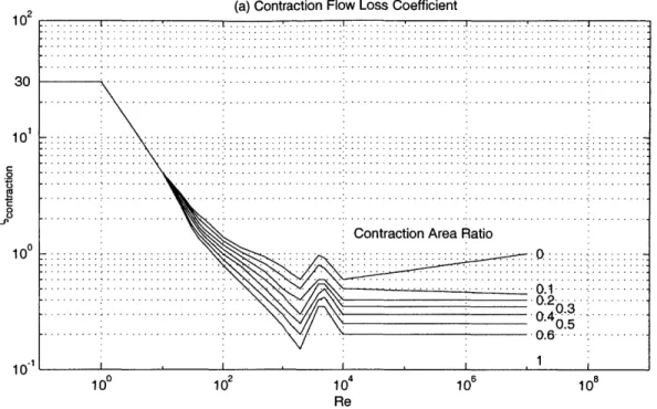
9.34 Plot of flow resistance coefficient versus Reynolds number for a generic flow orifice contraction structure. . . . 268
9.35 Device AV estimated laminar, transition, and turbulent flow regimes based on
experim ental data. . . . 269
9.36 Schematic of vorticity formation in contraction and expansion fluid flow sections. 270 9.37 Laminar, transition, and turbulent representive flow behavior . . . 271 9.38 Device AVI valve cap time histories under varying duty cycle voltage waveforms
to piezoelectric drive element. . . . 273
9.39 Device AV model correlation to experimental flow rate results for varying duty
cycles. . . . 274 9.40 Device AV dynamic flow regulation model correlation at 1kHz for varying
Nomenclature
A, high frequency channel cross-sectional area
Ap piezoelectric material area
Api, drive element piston area
AVc valve cap area
Avm valve membrane area
dPHAC hydraulic amplification chamber pressurization
dVEHC fluid volume change within external energy harvesting chamber
dVflsid hydraulic amplification chamber fluid volume change
dVii drive element piston swept volume
dVe drive element tether swept volume
dVe drive element total swept volume dV,, top structural plate volume change dVm valve cap and membrane swept volume
d33 piezoelectric material coefficient
Ep piezoelectric material Young's modulus
Ej silicon Young's modulus Epyrex Pyrex Young's modulus
fR fillet radius
F, force on valve cap structure
Fvm valve membrane force on top structural plate
G8j silicon shear modulus
HHAC hydraulic amplification chamber height
KEHC generalized external energy harvesting chamber stiffness
Kf fluid bulk modulus
L, high frequency channel length
Lp piezoelectric material length
Noh number of valve heads used in parallel within active valve
Pbias hydraulic amplification chamber bias pressure
PEHC external energy harvesting chamber pressure PEHC pressure within inlet valve orifice channel
PHAC PHPR PLPR Ppis P P2
Qin
Q
out Rbot, Dbot RC, Rorifice, Dorifice Rp, Dp Rpis, Dpis Rte, Dte Rtop, Dto, Rvc, Dvc Rvm, Dvm RE REDorifice tbot tpis ttetop ttebot ttoP tvc tvm T VP VHAC Whys Zbot Zde Zp Zpishydraulic amplification chamber pressure high pressure reservoir pressure
low pressure reservoir pressure
applied pressure beneath drive element piston generalized pressure above valve cap
generalized pressure above valve membrane flow rate through inlet valve
flow rate through outlet valve
bottom structural plate radius, diameter
piezoelectric material spacing radius from drive element center valve fluid orifice radius, diameter
piezoelectric material radius, diameter drive element piston radius, diameter
drive element tethers outer radius, diameter top structural plate radius, diameter
valve cap radius, diameter valve membrane radius, diameter generalized Reynolds number
Reynolds number through valve orifice bottom structural plate thickness drive element piston thickness top drive element tether thickness bottom drive element tether thickness top structural plate thickness
valve cap thickness valve membrane thickness piezoelectric material stress piezoelectric material voltage
hydraulic amplification chamber volume hysteretic energy consumption of active valve bottom structural plate deflection
drive element total deflection piezoelectric material deflection drive element piston deflection
Zte ztOp Zvc Zvc,opening Zvc,stroke ep VP VPyreX Vsi Pf luid 9vm c-vm,max (orifice
Zpis' -Zpis, -dVpis, -dVpis
=~F ''P - ,
Ztetop Ztetop' IdVtetop' 'dVtetop
=F -_P
EZtebot' -Ztebot
~Zbot
=F _P =F =~P
Ztop' 7Ztop' -dVtop, 7dVtop
F =P =F =m P
~Zvc,
-Zvc, -dVvml -dVvmtop drive element tether deflection top structural plate deflection
valve cap deflection (absolute)
valve cap opening distance from orifice valve cap peak-peak stroke
silicon shear correction factor piezoelectric material strain
piezoelectric material Poisson ratio Pyrex Poisson ratio
silicon Poisson ratio fluid density
valve membrane radial stress
maximum valve membrane radial stress valve orifice loss coefficient
drive element piston compliance coefficients top drive element tether compliance coefficients bottom drive element tether compliance coefficients bottom structural plate compliance coefficient top structural plate compliance coefficients valve cap and membrane compliance coefficients (linear deformation theory)
Chapter 1
Introduction
1.1
Motivation
The development of a fluidic microvalve, capable of high frequency control of high pressure liquid fluid flows, is a key task in the realization of high specific power (W) micropumping technology. Currently, many research efforts around the world are underway to develop compact liquid micropumping systems, the term "micro" referring to devices which are created with fabrication procedures capable of pm-size tolerances and which produce overall micropump dimensions on the order of a few millimeters to a few centimeters. However, the vast majority of these systems are designed for low pressure and low flow rate applications [1] [2] [3] [4] [5] such as drug dispensing and microdosing [6] [7] [8]. The higher performing of these systems are capable of pumping liquids with flow rates on the order of 1000-300O-L (0.017-0.050"$) against differential pressures of between 10kPa and 50kPa. With a typical device mass on the order of -1 gram, these performance values correlate to device-level specific powers below 2.5 kg'.
In an effort to develop high specific power micropumping technology (with specific powers
~100-10001) for both actuation and power generation applications, a novel class of Micro-Hydraulic Transducer (MHT) devices has been introduced [1] [10] [11] [12] [13]. These devices combine bulk piezoelectric materials with stiff micromachined structural elements and are de-signed to enable high frequency pumping of fluid (10-20kHz) against pressure differentials on the order of ~-1-2MPa, creating flow rates near or in excess of 1-"L
Piezoelectric materials are well-suited for transducer applications because of their inherently high peak specific powers. Figure 1.1 provides a comparison of the single stroke specific energy (L), bandwidth (kHz), and theoretical peak specific power (I) for a variety of transducer ma-terials [14] [15] [16]. The product of a material's single stroke specific energy and its bandwidth provides a value for the material's specific power (W). Shape-memory alloy materials (denoted
com-parison to that of standard polycrystalline piezoelectric materials such as PZT-5H (- 10 ). The maximum operational frequency, or bandwidth (~ 10Hz), of SMA materials, however, is significantly less than that of standard piezoelectrics (~ 100kHz). SMA materials and standard piezoelectrics both possess specific powers near 100-kg, however, their optimal implementation as actuation mechanisms is far different. In an application where low frequency, large stroke ac-tuation is desired (such as an on-off microvalve), the use of an SMA material might be preferred over a standard piezoelectric material. Conversely, for an application whereby high frequency, low stroke actuation is required, a piezoelectric material may be preferred. In fact, for this reason, the vast majority of high frequency micropumping systems use piezoelectric materials as their actuation mechanism in conjunction with fast-acting valves. The recent development of single-crystal ferroelectric materials (e.g. PZN-PT), characterized by specific powers approach-ing 10kW (-100x greater than those of standard polycrystalline PZT materials) [17], offers further advantages in strain capability over the standard piezoelectrics. These high performing materials, however, have yet to be integrated within high frequency micropumping systems.
The piezoelectric micropumping devices and systems that have been presented in the lit-erature up until this time typically utilize one of two actuation methods as a means to pump fluid: either (1) a deposited thin-film, thick disk, or bimorph of piezoelectric material [2] [3]
[6] in contact with a compliant membrane, or (2) a direct-drive stack actuator in contact with
a moveable silicon diaphragm. The thin-film, thick-film, and bimorph structural designs pre-sented are not conducive to both high force and high-frequency operation. The direct-drive stack actuation designs [18] [19] [20] are capable of achieving higher frequency operation than the thin-film, thick-film, and bimorph designs, however the presented micropump devices us-ing these designs are limited in their flow rate, pressurization, and frequency capabilities due to inadequacies of the accompanying one-way passive valves used to regulate the fluid flow. Additionally, these previously presented direct-drive stack designs require a significant length of piezoelectric actuation material to create the deflection and fluid pumping volume required for reasonable fluid flow rates. Due to this significant actuator size, an epoxy bonding agent and a relatively compliant silicon diaphragm are required to tolerance the piezoelectric material within the structures. The key design feature which differentiates Micro-Hydraulic Transducer devices from these previous piezoelectric micropumps is the incorporation of a stiff microma-chined structural "piston-like" actuation element not only within the pumping chamber of the device, but also within accompanying flow regulation active valves. The annularly-tethered micromachined "piston" structure, driven by miniature bulk piezoelectric elements (almost an order of magnitude smaller than those used in [18] [19] [20]) attached using a thin-film eutectic alloy bond, can achieve structural frequencies well above 10kHz and can actuate against fluid pressurizations near IMPa. The implementation of such a stiff structure within fluidic systems can enable significantly higher frequency and pressurization capabilities than the previously
Specific Work vs. Frequency --..-.-.--.-105 10 3 'p ~94, >ZT-6~ 10 10 10 Frequency (kHz) 10 10, 10,
Figure 1.1: Upper bound on specific work vs. frequency for various actuation media. SMA is shape-memory alloy; PZN-PT is single-crystal piezoelectric; MSM is magnetic shape memory materials.
presented piezoelectric micropumps.
As shown in Figure 1.2, a Micro-Hydraulic Transducer system consists of a piezoelectric pump chamber, two actively controlled valves, and a low and high pressure fluid reservoir. In the MHT actuator, electrical energy supplied to the piezoelectric pump chamber results in a pumping of fluid through the valves from the low to high pressure reservoir. In the MHT power harvester, sequenced operation of the valves results in fluid flow from the high to low pressure reservoir, producing a "pinging" of the piezoelectric element within the pump chamber. This cyclic strain on the element induces electrical charge, which can be rectified and stored. The specific power of these transducer devices scales linearly with the frequency of operation and the pressure drop across which the device can operate. Since structural frequencies scale inversely with the geometric size of the device, it is advantageous to build these systems as small as
Pnebmat 10, 0 0. CL, MSM ZN:PT Magnetostrctor -PTra~ HSydrauic SMA - -10' 10 10
"
icpossible, hence the need for MEMS fabrication and process technologies. The performance of these MHT systems is directly governed by the capabilities of the active valves, which regulate flow into and out of the pump chamber. As a result, to achieve high specific power Micro-Hydraulic Transducer devices, a compact high frequency, high pressure active valve is required. The development of such an active valve is the subject of this thesis.
Valve Control
Pump Chamber
Active Valve Active Valve
Fluid Flow High
Low Pressure Pressure -Electrical Power (a) Valve Control Pump Chamber
Active Valve Active Valve
Hregur FLodwlo
Pressu0X -m. Pressure
Electrical Power (b)
Figure 1.2: Schematics of Micro-Hydraulic Transducer systems: (a) MHT actuator system,
(b) MHT power harvesting system. High specific power is achieved through the integration of
piezoelectric material with structural stiff small-scale hydraulic systems.
1.2
Overview of Previous Microvalve Technology
Although a significant amount of literature is available describing the development of active valve devices and technology, few if any have been designed for high frequency control of high pressure liquid fluid flows. Novel microvalve designs using thermopneumatic actuation [21] [22], thermal bimetallic actuation [24], SMA actuation [23], electrostatic actuation [25]
[26], electromagnetic actuation [27] [28], piezoelectric bender-type actuation (both thin-film
and thick film) [29] [30] [31], and piezoelectric stack-type actuation [18] [19] [20] have been presented. A sampling of previously reported microvalves is shown in Figure 1.3 and Figure
gas inlet valve boss
metallization
top glass cap inlet pressure
botosilicon vapor glass
cap
gas outlet
(a) Thermopneumatic Actuation (b) Thermal Bimetallic Actuation
TiNi actuator
OPEN spacer OUT
layer
VALVE CLOSED _ electrodes fluid out fluid in.
bossOU
CLOSED bN
VALVE OPEN
I
~
V norifice
(c) Shape Memory Alloy Actuation (d) Electrostatic Actuation
SOLENOID
magnetic core silicon microvalve chip
non-magnetic core retainer
(e) Electromagnetic Actuation
Figure 1.3: Previously reported microvalves: (a) thermopneumatic actuation, Rich [22], (b) thermal bimetallic actuation, Jerman [24], (c) shape memory alloy actuation, Huff [23], (d) electrostatic actuation, Huff [25], and (e) electromagnetic actuation, Pourahmadi [27].
Figure 1.3(a) shows a thermopneumatic microvalve [22] for control of gas flows. A valve cen-tral boss is supported by a corrugated silicon membrane. The deflection of the boss is controlled
by the vapor pressure of the heated working fluid (parylene) within the contained chamber. A
micromachined heater grid exists within the chamber to increase the fluid temperature. For typical operation, a temperature of 800C (and a corresponding power dissipation of 300mW) is required to move the valve boss through a stroke of 9pm in a time of approximately 15 seconds. Maximum pressure rise within the fluid chamber was reported to be 100kPa.
Figure 1.3(b) illustrates a thermal bimetallic valve [24] for use in pneumatic closed-loop pressure or flow control applications. The valve consists of a diaphragm actuator with a cen-tral boss which mates to an etched silicon valve body. The actuator includes a circular silicon diaphragm with integrated diffused resistors and an annular region of deposited aluminum. As current is passed through the resistors, the diaphragm increases in temperature. The thermal expansion mismatch between the silicon and aluminum results in a controlled displacement of the central boss. An operational boss deflection of 15pm was obtained in response to a temper-ature increase of 1000C (and a reported corresponding power dissipation of 1W). Regulation of 200kPa differential pressure gas flows in an on-off fashion was demonstrated, resulting in gas flow rates of up to 2mL/s. No actuation response time was reported.
Figure 1.3(c) displays a shape-memory alloy (titanium nickel) actuated microvalve [23] for precise regulation of liquid fluid flow in micro-chemical analysis and drug delivery applications. The shape-memory effect is an athermal phase transformation between the austenitic (high temperature rigid) and martensitic (low temperature ductile) phases. In this valve, a TiNi diaphragm with attached silicon boss is actuated to open and close against a micromachined orifice. The valve was tested in an on-off fashion and it was reported to enable a liquid (DI water) flow rate of
0.lmL/s
for an applied differential pressure of 5kPa. Maximum stroke of the valve boss was not reported.Figure 1.3(d) displays an electrostatic microvalve [25] with a pressure-balancing structural feature that allows it to control fluids at pressures significantly larger than the necessary actua-tion pressure. The fluid provides a balancing force on the moving part of the structure thereby reducing the force required to open the valve. The moving part of the valve is a plunger which is actuated vertically, and consists of a center-bossed circular base and cap. Electrostatic ac-tuation is enabled through a small gap between the underside of the membrane and the top surface of a bottom support structure. This on-off valve was able to control 220kPa differential gas flows with an actuation voltage of 210V, resulting in a peak flow rate of 2.5mL/s. Due to significant ohmic heating in the device (because of a poor oxide layer), power dissipation was reported to be greater than 10W.
Figure 1.3(e) illustrates an electromagnetic microvalve [27] designed for applications requir-ing large stroke and large on-off gas flow rates. The microvalve consists of a solenoid housrequir-ing
Pori
piezo ceramic valve cap
Valve seat 7(Pieroele icm) Vatvmca Boom- -Electrothe valve seat PO- Si substrals
(a) Piezoelectric Thin-Film Actuation (b) Piezoelectric Thick-Film Actuation
7 k
~
pyrex glasssilicon
epoxy resin gas or liquid
glass tube holder stack piezo actuator
(c) Piezoelectric Stack Actuation
Figure 1.4: Previously reported piezoelectric microvalves: (a) piezoelectric thin-film actuation, Watanabe [30], (b) piezoelectric thick-film actuation, Kluge [31], and (c) piezoelectric stack actuation, Esashi [19].
and a plunger which is rigidly attached to a diaphragm structure. Current applied to the solenoid results in a motion of the plunger against a micromachined orifice. Dimensions of the solenoid attachment are unknown, however the author states that the application for this valve does not require the device to fit within a compact volume. For on-off operation, this direct drive is reported to achieve a maximum valve cap displacement of 100pm against a differential pressure of 90kPa, resulting in peak flow rates near 5mL/s. Power dissipation was reported to be greater than 1W.
Figure 1.4(a) displays a portion of a piezoelectrically-driven microvalve matrix [30] for con-trolling precise levels of gas flow. The valve is constructed of a thin beam with a round valve cap at the center and a valve seat of piezoelectric thin-film bifurcated in the normal direction.
The valve is normally closed due to a residual stress in the beam. For voltage applied to the valve seat, the piezoelectric film shrinks and the inner edge moves radially outward thereby increasing the flow area between the valve cap and this inner edge. The outer diameter of the piezoelectric thin-film is 600pm and its thickness is 1pm. In response to a voltage of 1V, the valve was reported to actuate against a differential pressure of 0.1kPa, resulting in a gas flow rate of 2mL/s.
Figure 1.4(b) illustrates a thick-film piezoelectrically-actuated microvalve [31] for use in high gas flow applications. The valve consists of a micromachined valve cap and membrane structure with an attached (via epoxy) piezoceramic disk to actuate the valve cap against a micromachined valve seat orifice. The valve seat diameter is 2.25mm and the achievable stroke of the valve cap is 30pm for an applied voltage of up to 3000V. For on-off operation, the valve was reported to regulate gas flow at 11.6Hz against a differential pressure of 400kPa. The thickness of the piezoceramic disk structure was not detailed.
Figure 1.4(c) displays a piezoelectrically-driven microvalve [19] using a direct drive piezoelec-tric stack as the actuation mechanism. This valve was designed for use in a liquid micropumping system. The microvalve consists of one silicon and two glass layers anodically bonded together. The silicon contains a inlet through hole, a flow channel, and a moveable diaphragm with a central boss structure. A piezoelectric stack 9mm in length is attached to the underside of the boss using epoxy. In response to a voltage of 90V at a frequency of 30Hz, an estimated liquid pressurization of 8kPa in the pumping chamber of the micropump and a corresponding flow rate of 0.00025mL/s was reported.
The previously described microvalves were selected to illustrate the wide variety of actua-tion concepts previously reported in the literature. All of these microvalves share a common operational geometry (except for Watanabe [30]) in that a valve boss is affixed to a diaphragm or membrane structure which carries the boss through a predetermined stroke, in response to some form of actuation principle. The majority of these valves were designed for gas flows, and as such estimating their capabilities in handling liquids is difficult to do, although typically flow rates of liquids for a given differential pressure can be expected to be 100-1000x smaller than gas flow rates under the same differential pressures. In general, based on their reported capabilities, it can be concluded that none of these valves is capable of simultaneously satisfying the set of high frequency (1-10kHz), high pressure (0.1-IMPa), and large stroke (15-40pm) requirements needed within full MHT liquid micropumping systems.
The thermal actuation designs (based on thermopneumatic, thermal bimetallic, and shape memory alloy principles) potentially can achieve large stroke and reasonable actuation force. However, these thermally-based devices exhibit excessive power consumption and poor response times on the order of seconds. High-frequency actuation in the kHz range is therefore unachiev-able. The electrostatic devices are limited in their deflection and pressure generation
capabili-ties, since the electrostatic force generated between two parallel plates scales inversely with their spacing and since electrical breakdown across the gap must be avoided. The electromagnetic concept is impeded by the overall size of external solenoid and housing structures needed to ac-tuate the valve structure. Piezoelectric thin-film and thick-film bender-type designs are limited in their ability to generate both high force and large deflection output. Shoji and Esashi's work aimed at solving this problem through the use of a stack-type piezoelectric actuator material to directly drive the valve membrane. In doing so, however, the piezoelectric stack material was required to be long (~9mm), resulting in a large actuator mass and size. The operational frequency of this device was reported only up to 30Hz.
A promising method for achieving high frequency operation in conjunction with large force
and high stroke capability would be to design a microvalve with a means to amplify the stroke of a piezoelectric bulk-type material (for example 1mm in thickness - almost an order of mag-nitude smaller in length than Shoji and Esashi's stack) into a larger valve membrane stroke. This could be done using a stiff hydraulic fluid within an enclosed chamber to couple the piezo-electric material motion to the valve cap motion using an area ratio amplification concept. This type of structure would thereby achieve high frequency, high pressure, and large valve cap stroke actuation with minimal device power consumption (a further advantage of piezoelectric materials). Numerous macroscale piezoelectric hydraulic amplification mechanisms have been presented in the literature. In an application for active vibration control, a piezoelectric ac-tuator uses the volume change of a piezoelectric ring to create a large deflection of a smaller area contact surface [32]. In an application for vibration control of a rotary dynamic system, the deflection of a stack-type piezoelectric actuator is coupled through a hydraulic line to a smaller size piston, which helps to control the motion of a rotating shaft [33]. These and other [34] piezoelectric hydraulic amplification mechanisms are novel in design, yet do not face the difficult fabrication, assembly, and tolerancing challenges inherent in the development of high frequency MEMS-scale devices.
1.3
Concept
This thesis focuses on the design, modeling, fabrication, and experimental testing of a piezoelec-trically driven hydraulic amplification microvalve for high pressure, high frequency applications. The proposed microvalve is shown in Figure 1.5. This device is desired to achieve large valve cap stroke (up to ~40pm) against high pressure loads (~0.1-1MPa) through a novel hydraulic am-plification mechanism that converts the small displacement (-lpm) of a piezoelectric material element into a significantly larger valve cap stroke. The inherent stiffness of the piezoelectric material and the hydraulic fluid chamber enable both high-frequency and high-force actuation capabilities.
8 mm
Fluid Flow OUT
Valve Cap/Membrane
Valve Stop
Hydraulic Amplification
Chamber Fluid Flow IN
- 5 mm Top Support Structure
Piezoelectric
Cylinder Drive Element Tethers
Drive Element Piston
Bottom Support Structure
Figure 1.5: Schematic of a piezoelectrically-driven hydraulic amplification microvalve. The primary structural components are designated with arrows. External hydraulic system pressure loading is applied on the top surface of the valve cap and membrane.
The active valve consists of three primary components: a piezoelectric drive element, an enclosed fluid amplification chamber, and a membrane with attached valve cap. The drive element incorporates a circular piston structure supported from beneath by one or more small bulk piezoelectric cylinders and is suspended circumferentially from a surrounding support structure by thin annular micromachined tethers. This novel compact "piston-type" design enables high frequency actuation against a large external pressurization due to the high stiffness of the piston structure and integration of miniature bulk piezoelectric elements beneath the piston using a thin-film bond layer. The lateral dimensions of the tethers are designed to make the tethers compliant enough to allow for rigid piston motion up and down, yet stiff enough to resist bowing under pressurization caused by the hydraulic fluid above the tether during actuation. The tethers provide a seal between the hydraulic fluid above the piston and the piezoelectric chamber below the piston, and also provide a path for electrical contact to the top surface of the piezoelectric cylinders. The fluid chamber resides between the top surface of the drive element piston and the bottom surface of a thin, smaller diameter silicon micromachined valve cap membrane. These design features enable the valve device to simultaneously meet a set of high frequency, high pressure, and large stroke requirements that have not previously been satisfied by other microvalves presented in the literature.