HAL Id: inria-00601906
https://hal.inria.fr/inria-00601906
Submitted on 21 Jun 2011
HAL is a multi-disciplinary open access
archive for the deposit and dissemination of sci-entific research documents, whether they are pub-lished or not. The documents may come from teaching and research institutions in France or abroad, or from public or private research centers.
L’archive ouverte pluridisciplinaire HAL, est destinée au dépôt et à la diffusion de documents scientifiques de niveau recherche, publiés ou non, émanant des établissements d’enseignement et de recherche français ou étrangers, des laboratoires publics ou privés.
A formal semantics of PLC programs in Coq
Sidi Ould Biha
To cite this version:
Sidi Ould Biha. A formal semantics of PLC programs in Coq. IEEE Computer Software and Appli-cations, COMPSAC’11, Jul 2011, Munich, Germany. �inria-00601906�
A formal semantics of PLC programs in Coq
Sidi OULD BIHA
FORMES project, INRIA and Tsinghua University Beijing, China
Sidi.Ould [email protected]
Abstract—Programmable logic Controllers (PLC) are embedded systems that are widely used in industry. We propose a formal semantics of the Instruction List (IL) language, one of the five programing languages defined in the IEC 61131-3 standard for PLC programing. This semantics support a significant subset of the IL language that includes on-delay timers. We formalized this semantics in the proof assistant Coq and used it to prove some safety properties on an example of PLC program.
I. Introduction
Programmable Logical Controllers (PLC) are micro-processor based control systems. They are used in a wide range of industrial applications, from automotive industry and chemical plants to home appliances. PLC applications are critical in a safety or economical cost sense. The recent events of the recall of a large amount of cars for some safety problems caused by a programming bug, are just a new example of a how the cost of such errors can easily get out of proportion. This is more relevant for PLC programs because they are generally used to perform repetitive actions. Thus the use of formal methods and specially theorem proving in the PLC programs development process, will increase the confidence in such programs.
Instruction list (IL) is one of the five programing languages defined in the IEC 61131-3 standard [1]. With the graphical language ladder diagrams (LD), they are the most widely used languages for pro-graming PLC. The definition of a formal semantics of IL is a prerequisite for the development of a generic tool for verifying PLC programs written in IL. Since most of PLC compilers use IL as an
This research work is funded by the ANR grant ANR-08-BLAN-0326-01 for the SIVES project.
intermediate language in the compilation process to machine code, a formal semantics of IL is also nec-essary for the development of a certified compiler for PLC. This work is the first step towards the development of a certified compiler for PLC pro-grams. It also provides a basis for the development of a static analyzer for PLC programs.
There are many examples of the use of formal methods for the verification of PLC programs [2], [3], [4]. Most of these examples use model checking. In some of these works, an operational seman-tics of PLC programs is defined. We extend the operational semantics defined in [5] to support a larger subset of IL instructions (timers...) and the cyclic behavior of PLC programs. We formalized this semantics in the proof assistant Coq [6] using its extension SSReflect [7].
In this paper, we give in the first section a brief presentation of PLC systems. In the second section we present a small step operational semantics of the IL language. The formalization of this semantics in the proof assistant Coq and an example are described in the third section. Related works and conclusions are presented in the two final sections.
II. Programmable Logic Controller A PLC is composed of a microprocessor, a mem-ory, input and output devices where signals can be received from sensors or switches and sent to actuators. A main characteristic of PLC is there execution mode. A PLC program is executed in a permanent loop. In each iteration of the execution loop, or scan cycle, the inputs are read, the pro-gram instructions are executed and the outputs are updated. Figure 1 shows the sequencing of the 3 phases of the scan cycle. The cycle time is often fixed or has an upper bound limit. It depends on the manufacturer and type of the PLC.
Inputs scan instructions execution Outputs scan
Figure 1. Schema of PLC scan cycle
A. Programing languages
Since the introduction of PLC in the industry, each manufacturer has developed its own PLC programming languages. In 1993, the International Electrotechnical Committee (IEC) published the IEC 1131 International Standard for PLC. The third volume of this standard defines the program-ming languages for PLC. It defines 4 languages :
• Ladder Diagrams (LD) : graphical language
that represent PLC programs as relay logic diagrams.
• Functional Block Diagrams (FBD) : graphical
language that represent PLC programs as con-nection of different function blocks.
• Instruction List (IL) : an assembly like
lan-guage.
• Structured Text (ST) : a textual (PASCAL
like) programing language.
The standard defines also a meta language called Sequential Function Charts (SFC). It corresponds to a graphical method for structuring programs and allows to describe the system as a state transition diagram. Each state is associated to some actions. An action is described using one of the PLC pro-graming languages like LD or IL. SFC are well suited to write concurrent control programs. We present later in more details the IL language, the main focus of this work.
B. Timers
In the context of PLC applications, there is often the need to control time. For example, a motor might need to be activated or switched off for a particular time interval. Another example, in a chemical plant a valve is open and a tank will be full
after a period of time. PLC timers are components that set on a boolean output after or for a period of time following the activation of a boolean input. They are used to control output signal duration or as input signal for time dependents PLC programs. In general, they have two inputs and two outputs.
Txx
TIME PT BOOL IN
ET TIME Q BOOL
Figure 2. Standard timer representation
Figure 2 shows the IEC 61131-3 standard graphical representation of timers. In this representation, IN and Q are respectively the boolean input and output of the timer. PT is the constant input used to specify the time delay of the timer. ET is the output indicating the elapsed time since the activation of the timer. The delay PT and elapsed time ET are multiples of a system predefined time base.
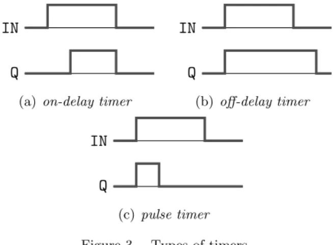
IN Q
(a) on-delay timer
IN Q (b) off-delay timer IN Q (c) pulse timer Figure 3. Types of timers
There is three basic types of timers that can be found with PLC. The IEC 61131-3 standard defines the :
• on-delay timers (TON) : they come on after a
time delay following the activation of the input (Figure 3(a)).
• off-delay timers (TOF) : they stay on for a
fixed period of time after the input goes off (Figure 3(b)).
• pulse timers (TP) : they turn on for a fixed
period of time after the input goes on (Fig-ure 3(c)).
III. Instruction List language A. General structure
The IEC 61131-3 standard defines an Instruction List program as a list of variables (input, output and local) declarations followed by a list of instruc-tions. An instruction contains an operator followed by a list of operands. Most of IL instructions take one operand, but some like timers instructions need more than one operand. A label followed by a colon (:) can be inserted before an instruction. An example of IL program is the following:
LABEL OPERATOR OPERAND
l1: LD x
ADD 3
JMP l1
The meaning of some IL operators can be changed using modifiers. In particular, the standard defines the two modifiers: C and N. The C modifier indi-cates that the corresponding instruction should be executed only if the current evaluated result is the boolean value true. It can be used with branch-ing instruction or functions call. The N modifier indicates that the operand of the corresponding instruction should be negated. If it is combined with the C modifier, it means that the corresponding instruction should be executed only if the current evaluated result is the boolean value false. It can be used with branching instruction, functions call or booleans operators. For example, the instruction JMPCN l1will be executed only if the current eval-uation is false.
B. Model choices
The IEC 61131-3 standard was published after many PLC manufacturers have defined and imple-mented their own programming languages. It does not give a clear description of the semantics of PLC languages. It does not also specify how PLC timers should behave. We saw previously that a PLC timer have two outputs : the boolean output and the elapsed time since the timer activation output. How this output are updated is not described by the standard. In practice, PLC manufacturers defines two types of timers according to the way their outputs are updated. In the first category, outputs can be updated only if the timer instruction is
executed. For this kind of timers, a time error is introduced depending on the timer delay variable and the program cycle duration. In the second category, timer outputs are automatically updated by a system routine. In this case a time error is introduced depending on the position of the timer instruction in the program. The execution of the timer instruction is only required to check the state of the outputs. Both timers are not ideal timers and the time error should be taken into account by the PLC programmer when defining the timers delay input.
Our IL model is a significant subset of the lan-guage defined by the IEC 61131-3 standard. This subset covers assignments instructions and boolean and integer operations. It covers also comparison and branching instructions and on-delay timers. We choose to consider only booleans and integers as basic data types. In most of PLC systems, reals are available as basic data types. But in practice, real numbers computation cost much time and they are often delegated to a PC that can communicate with the PLC. This is motivated by the need to keep the program scan cycle within a relatively small time upper bound. In this work we will consider only TON timers. The other two kinds of timers can be treated similarly. We will also suppose that the outputs of the timers are updated only when the timer instruction is executed. This is the case in most of the timers provided by PLC manufacturers. We will also suppose that in an IL program, a timer instruction is called only once with the same output variable. This is needed to keep the time error for the timer less than an cycle duration.
The IL subset we work with does not include function call or counters instructions. In our model, we also choose to work with simple IL operators. In particular, the IL language support binary opera-tors that use a stack for the operation execution. The IL subset we deal with does not includes this operators. An extension of our semantics to support these operators and the function call should not be difficult.
C. Syntax
Each IL program start with variable declarations. We will denote the type of IL variables by Var. These declarations specify for each variable if it is
an input (V arin) or/and output (V arout) or a local
variable (V arloc). In addition to standard variables,
IL have a specific register where every computation takes place. This special register will be denoted reg.
P ::= { varin; list input variables
varout; list output variables
varloc; list local variables
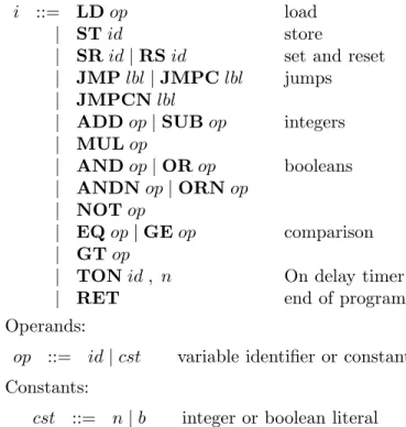
body; } list of instructions After the variable declarations, the IL program body follows with a list of instructions. As we mentioned before, an IL instruction is composed of an operator and one or more operands. An operand can be a variable or a constant.
Instructions:
i ::= LD op load
| ST id store
| SR id | RS id set and reset
| JMP lbl | JMPC lbl jumps
| JMPCN lbl
| ADD op | SUB op integers
| MUL op | AND op | OR op booleans | ANDN op | ORN op | NOT op | EQ op | GE op comparison | GT op
| TON id , n On delay timer
| RET end of program
Operands:
op ::= id | cst variable identifier or constant Constants:
cst ::= n | b integer or boolean literal We will denote the set of IL instructions by Instr. For simplicity, we suppose that IL program labels are natural numbers. Since an IL program is a list of instruction, a label will indicate the position of the corresponding instruction in the list. For a given program P and an index i, P (i) ∈ Instr represent the instruction of P at the position i.
D. Operational semantics
We defined a small step operational semantics of IL programs. This semantics extend the one defined in [5] to support on-delay timers and the cyclic behavior of PLC programs.
Modes: as we mentioned in Section II, each IL program scan cycle contains 3 phases:
• I: input, • O: output,
• E: instruction execution.
The set of these execution phases will be denoted modes.
Cycles: we suppose having a global discrete time clock. Each program execution cycle is rep-resented by an identifier or its index in the time execution line. Every cycle is associated to its beginning time according to the global clock. The set of program execution cycles is denoted C ⊆ N. For a cycle c, the starting time is denoted tc and
the duration of every cycle is fixed and correspond to a global system constant δ = tc+1− tc.
States: a state is a function that associates to each variable of the program and the register a value. The set of state corresponds to:
S = {reg} ∪ V ar → D,
where D is the union of the IL variables data domains.
Configurations: elements of the set E = C ×S × N× mode. A configuration (c, σ, i, m) corresponds to a cycle identifier c, a state σ, a position index i and an execution mode m.
Transitions: relation on configurations ⊆ E×E. Figure 4 gives the inference rules of the IL configu-rations transitions relation. The transition system is defined by an initial configuration (0, σ0,0, I),
where σ0is the initial state that maps all the integer
variables to 0 and boolean variables to f alse. The first two transitions rules of Figure 4 cor-respond to the load and store instructions. In the first case the register is updated while in the second the variable state is updated. The transitions cor-responding to the set/reset instructions (rules SR and RS) update the variable state function with the corresponding values for the given operands. In the inference rule JMP, transition for the uncondi-tional branching instruction, there is no condition on the branching label value (position of the jump-ing target) compared to the current position of the program counter. This can lead to non terminating IL programs. In practice this should not be the case, since every IL program should terminate during the
LDP(i) = LD op σ′= σ[reg 7→ op] P ⊢(c, σ, i, E) → (c, σ′, i+ 1, E) P(i) = ST x σ′= σ[x 7→ reg] P ⊢(c, σ, i, E) → (c, σ′, i+ 1, E) ST SRP(i) = SR x σ′= σ[x 7→ x ∨ reg] P ⊢(c, σ, i, E) → (c, σ′, i+ 1, E) P(i) = RS x σ′= σ[x 7→ x ∧ ¬reg] P ⊢(c, σ, i, E) → (c, σ′, i+ 1, E) RS
JMPC-trueP(i) = JMPC lbl σ(reg) = T
P ⊢(c, σ, i, E) → (c, σ, lbl, E)
P(i) = JMPC lbl σ(reg) = F
P ⊢(c, σ, i, E) → (c, σ, i + 1, E) JMPC-false
JMPCN-false P(i) = JMPCN lbl σ(reg) = F
P ⊢(c, σ, i, E) → (c, σ, lbl, E)
P(i) = JMPCN lbl σ(reg) = T
P ⊢(c, σ, i, E) → (c, σ, i + 1, E) JMPCN-true
JMP P(i) = JMP lbl
P ⊢(c, σ, i, E) → (c, σ, lbl, E)
P(i) = ADD op σ′= σ[reg 7→ reg + op]
P ⊢(c, σ, i, E) → (c, σ′, i+ 1, E) ADD
SUBP(i) = SUB op σ′= σ[reg 7→ reg − op]
P ⊢(c, σ, i, E) → (c, σ′, i+ 1, E)
P(i) = MUL op σ′= σ[reg 7→ reg ∗ op]
P ⊢(c, σ, i, E) → (c, σ′, i+ 1, E) MUL
ANDP(i) = AND op σ′= σ[reg 7→ reg ∧ op]
P ⊢(c, σ, i, E) → (c, σ′, i+ 1, E)
P(i) = OR op σ′= σ[reg 7→ reg ∨ op]
P ⊢(c, σ, i, E) → (c, σ′, i+ 1, E) OR
ANDNP(i) = ANDN op σ′= σ[reg 7→ reg ∧ ¬op]
P ⊢(c, σ, i, E) → (c, σ′, i+ 1, E)
P(i) = ORN op σ′= σ[reg 7→ reg ∨ ¬op]
P ⊢(c, σ, i, E) → (c, σ′, i+ 1, E) ORN
NOTP(i) = NOT op σ′= σ[reg 7→ ¬op]
P ⊢(c, σ, i, E) → (c, σ′, i+ 1, E)
P(i) = EQ op σ′= σ[reg 7→ reg == op]
P ⊢(c, σ, i, E) → (c, σ′, i+ 1, E) EQ
GEP(i) = GE op σ′= σ[reg 7→ reg ≤ op]
P ⊢(c, σ, i, E) → (c, σ′, i+ 1, E)
P(i) = GT op σ′= σ[reg 7→ reg < op]
P ⊢(c, σ, i, E) → (c, σ′, i+ 1, E) GT
P(i) = TON T x, P t σ(reg) = F σ′= σ[T x.Q 7→ F, T x.ET 7→ 0]
P ⊢(c, σ, i, E) → (c, σ′, i+ 1, E) TON-off
P(i) = TON T x, P t σ(reg) = T T x.ET < P t σ′= σ[T x.Q 7→ F, T x.ET 7→ T x.ET + δ]
P ⊢(c, σ, i, E) → (c, σ′, i+ 1, E) TON-on
P(i) = TON T x, P t σ(reg) = T T x.ET >= P t σ′= σ[T x.Q 7→ T, T x.ET 7→ T x.ET + δ]
(c, σ, i, E) → (c, σ′, i+ 1, E) TON-end P(i) = RET P ⊢(c, σ, i, E) → (c, σ, 0, O)RET − →x : V arin σ′= σ[xi7→vi] P ⊢(c, σ, i, I) → (c, σ′, i, E) Input P ⊢(c, σ, i, O) → (c + 1, σ, i, I)Output
Figure 4. IL Operational semantics
scan cycle time limit. We chose here not to consider this kind of errors. They can be treated at the level of the syntactic analysis or by static analysis of the program.
The transition relation for the TON instruction is given by the rules off, on and TON-end of Figure 4. The elapsed time variable ET of the TON timer is incremented by the global constant δ when the timer is activated (the eval-uation register value is true). The timer output Q is activated when the elapsed time variable ET is greater or equal to the timer delay parameter PT. For the input transition, the variables state function is updated by the input variables values given by the program global environment. The output transition corresponds to the cycle identifier incrementation and the change of the configuration
mode. The program environment will have to read the variables state during this transition to get the values of the outputs of the system.
After this definition of the semantics of the IL language, we present in the next section our for-malization of this semantics in the proof assistant Coq.
IV. Coq formalizations
As we mentioned before, we intend to develop a certified compiler from IL to the C language. We choose to formalize the IL semantics in the Coq proof assistant to make it easier to connect our de-velopment to the already existing certified compiler for C : the CompCert [8] compiler. We also want to produce from this formal development a certified executable. The Coq extraction mechanisms will allow us to produce such executable.
In the reasoning about IL programs, we will have to deal with proprieties about booleans and naturals numbers. In this development, we chose to use the Coq extension SSReflect for its rich libraries on booleans and natural numbers. We also use SSReflect generic library for lists and its interface for types with decidable equality. More details about this libraries can be found in the SSReflect manual [7] and tutorial [9].
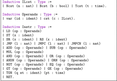
A. Syntax
The Coq system provides a very powerful mech-anism to define recursive or finite type or set. This mechanism is called inductive type and is very useful when defining the syntax of a programming language. We define the IL syntax presented in Section III-C, using the Coq inductive type mech-anism. The definitions are given in Figure 5. In these definitions, the types time and ident are a renaming of the Coq standard type nat. The first one corresponds to the type of variable identifiers. Since we consider discrete time, the type time is the type of time values. A piece of IL code corresponds to a list of instruction. We represent it as an element of the type code := seq Instr1
.
Inductive ILcst : Type :=
| Ncst (n : nat) | Bcst (b : bool) | Tcst (t : time).
Inductive Operands : Type :=
| var (id : ident) | cst (c : ILcst).
Inductive Instr : Type := | LD (op : Operands) | ST (x : ident)
| SR (x : ident) | RS (x : ident)
| JMP (l : nat) | JMPC (l : nat) | JMPCN (l : nat) | ADD (op : Operands) | SUB (op : Operands) | MUL (op : Operands)
| AND (op : Operands) | OR (op : Operands) | ANDN (op : Operands) | ORN (op : Operands) | NOT (op : Operands) | EQ (op : Operands) | GT (op : Operands) | GE (op : Operands) | TON (q et : ident) (pt : time)
| RET.
Figure 5. Coq definition of the IL syntax
B. Semantics
Our formalization of the IL semantics defined in Section III-D is parameterized by the following Coq global variables:
1
seqis the type of list in SSReflect.
Variables (delta : time) (pi : seq ident).
Variables (p_ival : nat → ident → nat) (P : code).
The variable delta represents the cycle duration time. The list of program input variables is rep-resented by pi. In order to define the semantics transitions, we need to know the input variables in order to update them with the values given by the program environment at the beginning of each cycle. Those values are represented by the function p_ival that takes as parameters a cycle identifier and a variable identifier and returns a value.
When we look at the definition of the transition relation for the IL semantics given in Figure 4, we notice that it can be decomposed into two sub-operations. First, there is the states updating function. It returns a new state according to the evaluated program instruction. Second, there is the program location successor. Normally it returns the incremented value of the current location, unless the instruction is a branching. The configuration transition function can be defined on top of the sub-operations just by checking the execution mode.
States: For the definition of the variable states and since booleans can be injected in integers2
, we choose to represent the natural numbers as the data domain of the IL variables. We define a state as an object of the type State.
Definition State:= nat ∗ (ident → nat).
Definition state_up s i v: State :=
ifiis(S n) then
(s.1, funx=>ifn== x thenvelse s.2 x)
else (v, s.2).
A program state s : State is a pair. The first element of the pair, denoted s.1, represents the value of the current register. The second element of the pair, denoted s.2, represents the function that maps every program variable to its value. We define also some state transformation function. The function state_up updates the value of a state s for a given variable determined by its second argument i with a value v. If i is equal to zero the current register value is updated otherwise the variables mapping function is updated.
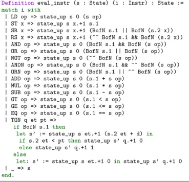
Instruction evaluation: The definition of the IL instruction evaluation function is presented in
Fig-2
Definition eval_instr (s : State) (i : Instr) : State :=
match i with
| LD op => state_up s 0 (s op) | ST x => state_up s x.+1 s.1
| SR x => state_up s x.+1 (BofN s.1 || BofN (s.2 x)) | RS x => state_up s x.+1 (~~ BofN s.1 && BofN (s.2 x)) | AND op => state_up s 0 (BofN s.1 && BofN (s op)) | OR op => state_up s 0 (BofN s.1 || BofN (s op)) | NOT op => state_up s 0 (~~ BofN (s op))
| ANDN op => state_up s 0 (BofN s.1 && ~~ BofN (s op)) | ORN op => state_up s 0 (BofN s.1 || ~~ BofN (s op)) | ADD op => state_up s 0 (s.1 + s op)
| MUL op => state_up s 0 (s.1 * s op) | SUB op => state_up s 0 (s.1 - s op) | GT op => state_up s 0 (s.1 < s op) | GE op => state_up s 0 (s.1 <= s op) | EQ op => state_up s 0 (s.1 == s op) | TON q et pt =>
if BofN s.1 then
let s’ := state_up s et.+1 (s.2 et + d) in
if s.2 et < pt then state_up s’ q.+1 0
else state_up s’ q.+1 1
else
let: s’ := state_up s et.+1 0 in state_up s’ q.+1 0
| _ => s
end.
Figure 6. IL instructions evaluation function
ure 6. It follows the inference rules given in Fig-ure 4. The function eval_instr takes two argu-ments, a state and an instruction, and returns a new state. For example, the evaluation of a load instruction will return an updated state where the current register is equal to the value of the instruc-tion operands. Another example is given by the set instruction SR x. For this case, the variable x is updated with the disjunction of its previous value and the value of the current register. For the opera-tors that are defined only for booleans values (like: SR, AND ...), we use the function BofN that return the original boolean value of a boolean variable that was translated to a natural numbers. In the definition of Figure 6 and the following definitions, we use an SSReflect notation for a natural number successor. When we write x.+1 this correspond to the successor of x or x + 1.
Configurations transition: the IL configurations, presented in Section III-D, are encoded as a Coq product type.
Inductive ILmode:= I | O | E.
Definition ILConf:= nat ∗ State ∗ nat ∗ ILmode.
In a configuration, cycle identifier and location are represented by naturals numbers. The execution mode is represented by an element of the inductive
Definition instr_succ (i : Instr) x (s : State) : nat :=
match i with
| JMP l => l
| JMPC l => if BofN s.1 then l else x.+1
| JMPCN l => if ~~ BofN s.1 then l else x.+1
| _ => x.+1
end.
Definition transition (Cf : ILConf) :=
match Cf with (c, s, l, m) =>
match m with
| I => let s’ := state_up_seq s pi (p_ival c) in
(c, s’, l, E) | O => (c.+1, s, l, I)
| E => let I := nth RET P l in
if I == RET then (c, s, 0, O)
else (c, eval_instr s I, instr_succ I l s, E)
end end.
Figure 7. IL Configurations transition function
type ILmode. The elements of this finite type cor-responds to the three modes we defined previously in Section III-D.
Since our IL semantics is deterministic, we define the configurations transition relation as a function. The Coq definition is given in Figure 7. The transi-tion functransi-tion proceeds by looking at the mode of the configuration passed as argument. If it is an input mode, the variables state function is updated by the new values of the input variables and the mode is changed to execution. The function state_up_seq is a generalization of the state updating function state_upthat updates a list of variables. When the original configuration has an output mode, the cycle identifier is incremented and the mode is changed to input. This two cases correspond to the inference rules Input and Output of Figure 4.
When the configuration mode is execution, the transition function will first check the instruction corresponding to the current configuration. This instruction corresponds to the lth element of the
list of instructions of the code P. We use here the generic function nth from SSReflect seq library. If the element at the position l of P is equal to RET then the rule RET of Figure 4 is applied. Otherwise the cycle and the mode will not be modified. The variable state will be updated using the function eval_instr. The configuration location is updated using the function instr_succ that returns the suc-cessor of a location according to the corresponding instruction and the state of the current register.
Program executions: After the definition of the IL configuration transition function, we define a program execution as the transitive closure of the transition relation. Since it is not always possible to know how many transition are needed to execute an IL program, we define the program execution as a propositional relation rather than a compu-tational function. The definition of exec is given
Inductive exec (c1 c2 : ILConf) : Prop := | exec_step : transition c1 = c2 → exec c1 c2 | exec_star cf : transition c1 = cf →
exec cf c2 → exec c1 c2.
Lemma exec_splitI_prodl : forall c n s0 s, exec (c, s0, 0, I) (c + n.+1, s, 0, O) →
exists r, exec (c, s0, 0, I) (c, r, 0, O) ∧ exec (c.+1, r, 0, I) (c + n.+1, s, 0, O).
Lemma exec_splitI_prodr : forall c n s0 s, exec (c, s0, 0, I) (c + n.+1, s, 0, O) →
exists r, exec (c, s0, 0, I) (c + n.+1, r, 0, I) ∧ exec (c + n.+1, r, 0, I) (c + n.+1, s, 0, O).
Figure 8. IL program execution definition and lemmas
in the Figure 8. It corresponds to the standard transitive closure predicate. In addition to this defi-nition, we prove some generic properties about any program executions. The first lemma of Figure 8 states that if the execution of a program starting from the configurations (c, s0, 0, I) ends at the configuration (c + n.+1, s, 0, O), it must come through a configuration where the cycle is the first execution cycle and the mode is output. The second lemma states the same property but for the last execution cycle. The proofs of this two lemmas are straightforward. They use induction and the property of monotonicity of the exec relation for cycles.
Using our IL semantics, we formalized a simple example of PLC program and proved some prop-erties about it. This is presented in the following sub-section.
C. Example
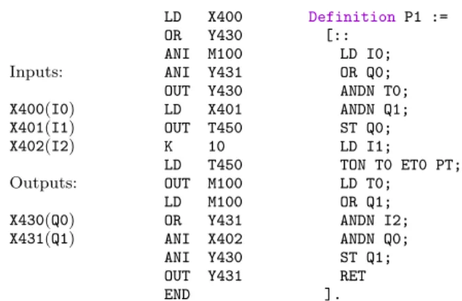
We formalized a simple example of PLC pro-gram written in the IL language. It is one of the examples given in the book Programmable Logic Controller s [10].
Description: We consider the example of a PLC program for opening and closing a car park
en-trance barrier. The barrier is opened when the cor-rect amount of money is inserted in the collection box. The barrier will stay open for 10 seconds. The program has three inputs and two outputs. The first input is associated to a sensor in the collection box. When the barrier is down it trips a switch and when up it trips another switch. These switches are associated to the two others input variables of the program. They give the position of the barrier to the program. The opening and closing of the barrier is managed by a valve-piston system. The two program outputs are associated to the two valves of this system. The program source
Inputs: X400(I0) X401(I1) X402(I2) Outputs: X430(Q0) X431(Q1) LD X400 OR Y430 ANI M100 ANI Y431 OUT Y430 LD X401 OUT T450 K 10 LD T450 OUT M100 LD M100 OR Y431 ANI X402 ANI Y430 OUT Y431 END Definition P1 := [:: LD I0; OR Q0; ANDN T0; ANDN Q1; ST Q0; LD I1; TON T0 ET0 PT; LD T0; OR Q1; ANDN I2; ANDN Q0; ST Q1; RET ].
Figure 9. Car barrier program in Mitsubishi format and in Coq
in the Mitsubishi format, which does not follow the standard, and the corresponding Coq definition are presented in Figure 9. The output Q0 for raising the entrance barrier is activated when the input I0 is activated. It remains on until the timer output variable T0 is activated. This happens when the input I1, indicating that the barrier is up, remains on for 10 seconds. At the end of the time delay the output Q1 is activated telling the valve-piston system to lower the barrier. In a normal state, the input variables I1 and I2 should have opposite boolean values. When they have the same values, it means the barrier is in the process of being lowered or raised.
Properties: we formalized and proved some safety properties about the IL program presented above. For example, Figure 10 shows two lemmas that prove some properties about the output Q0 and the timer output T0. The lemma barrier_open
Lemma barrier_open : forall c s0 s, exec (c,s0,0,E) (c,s,0,O) → BofN (s Q0) =
(BofN (s0 I0) || BofN (s0 Q0)) && ~~ BofN (s0 T0) && ~~ BofN (s0 Q1).
Lemma timer_on : forall c s0 s, exec (c, s0, 0, E) (c, s, 0, O) →
BofN (s T0) = BofN (s0 I1) && (PT <= (s0 ET0)).
Figure 10. IL Configurations transition
states that after one cycle execution, the output Q0 will be on if the input I0 was on at the input phase or Q0 was on in the previous cycle, and the timer output and the output Q1 were off during the previous cycle. The lemma timer_on states that the timer output will be on if and only if the input I1is on and the elapsed time is greater or equal to the predefined time delay. The proofs of this two lemmas are straight forward and proceed by case analysis over the inductive predicate exec.
V. Related works
There is numerous publications on the use of formal methods for the verification of PLC pro-grams. Model checking is the most used approach in these verification works. In [2] a semantics of IL is defined using timed automaton. The language sub-set contains TON timers but data types are limited to booleans. The formal analysis is performed by the model checker UPPAAL. In [3] an operational semantics of IL is defined. A significant sub-set of IL is supported by this semantics, but it does not include timer instructions. The semantics is encoded in the input language of the model checker Cadence SMV and linear temporal logic (LTL) is used to specify properties of PLC programs. Abstraction interpretation techniques are also used for the verification of PLC programs. In [5] an op-erational semantics of IL is defined. This semantics is used to perform abstract interpretation of IL programs by a prototype tool called HOMER. In the theorem proving community, there has been some work on the formal analysis of PLC pro-grams. In [4] the theorem prover HOL is used to verify PLC programs written in FBD, SFC and ST languages. In this work, modular verification is used for compositional correctness and safety proofs of programs. In the Coq system, an
exam-ple of verification of PLC program with timers is presented in [11]. A quiz machine program is used as an example in this work, but no generic model of PLC programs is formalized. There is also a formalization of a semantics3
of the LD languages in Coq. This semantics support a sub-set of LD that contains branching instructions. This work is a component of a CDK environment for PLC.
VI. Conclusions and future work Our goal is to develop a formally verified compiler and a verification tool for PLC programs. This require a formal semantics of PLC programing languages. In this paper we presented a formal semantics of PLC programs written in the IL lan-guage. This semantics covers a large sub-set of IL instructions that includes timers. We formalized this semantics in the type theory based theorem prover Coq and used it to prove some safety prop-erties of a simple example of PLC program. The proof of these properties are straightforward and require only some basic knowledge about the Coq system. Although our main goal is the development of a PLC certified compiler, this work can also be used for formally proving properties of IL programs. In the short term, the perspectives of our work are the following:
• Developing a certified compiler front-end for
PLC. We plan to formalize and certify a trans-formation of PLC programs written in LD language to IL.
• Integrating our formal semantics of IL with
the formal semantics of the meta language SFC [12]. This work will allow us to prove safety properties of industrial examples of PLC programs written in SFC.
In the long term, the work on the certified compiler front-end open the way to the development of a certified compilation chain for PLC. This chain can be build on top of the CompCert compiler and uses the BIP [13] framework as an intermediate language. We also plan to develop a static analysis tool for PLC programs.
3
Research report in Korean available at: http://pllab.kut. ac.kr/tr/2009/ldsemantics.pdf
References
[1] I. E. Commission, “IEC 61131-3 : Programmable controllers - programming languages,” IEC, Tech. Rep., 2003.
[2] A. Mader and H. Wupper, “Timed automaton mod-els for simple programmable logic controllers,” Real-Time Systems, Euromicro Conference on, pp. 01– 06, 1999.
[3] G. Canet, S. Couffin, J.-J. Lesage, A. Petit, and P. Schnoebelen, “Towards the automatic verification of plc programs written in instruction list,” in 2000 IEEE International Conference on Systems, Man, and Cybernetics, vol. 4, 2000, pp. 2449–2454. [4] N. V¨olker and B. J. Kr¨amer, “Automated
verifica-tion of funcverifica-tion block-based industrial control sys-tems,” Science of Computer Programming, vol. 42, no. 1, pp. 101–113, 2002.
[5] R. Huuck, “Semantics and analysis of instruction list programs,” Electr. Notes Theor. Comput. Sci., vol. 115, pp. 3–18, 2005.
[6] The Coq Development Team, The Coq System, http: //coq.inria.fr.
[7] G. Gonthier and A. Mahboubi, A small scale reflec-tion extension for the Coq system, iNRIA Technical report, http://hal.inria.fr/inria-00258384.
[8] X. Leroy, “A formally verified compiler back-end,” Journal of Automated Reasoning, vol. 43, no. 4, pp. 363–446, 2009.
[9] G. Gonthier and A. Mahboubi, “An introduction to small scale reflection in Coq,” iNRIA Technical report, http://hal.inria.fr/inria-00515548/PDF/ RR-7392.pdf.
[10] W. Bolton, Programmable Logic Controllers. Else-vier, 2006.
[11] H. Wan, G. Chen, X. Song, and M. Gu, “Formal-ization and verification of PLC Timers in Coq,” in Computer Software and Applications Conference, 2009. COMPSAC ’09. 33rd Annual IEEE Interna-tional, 2009, pp. 315–323.
[12] J. O. Blech, A. Hattendorf, and J. Huang, “To-wards a property preserving transformation from IEC 61131-3 to BIP,” CoRR, vol. abs/1009.0817, 2010.
[13] S. Bensalem, M. Bozga, T.-H. Nguyen, and J. Sifakis, “Compositional verification for component-based systems and application,” IET Software, Special Issue on Automated Compositional Verification: Techniques, Applications and Empirical Studies, vol. 4, no. 3, pp. 181–193, 2010.