HAL Id: hal-02419678
https://hal.archives-ouvertes.fr/hal-02419678
Submitted on 19 Dec 2019HAL is a multi-disciplinary open access
archive for the deposit and dissemination of sci-entific research documents, whether they are pub-lished or not. The documents may come from teaching and research institutions in France or abroad, or from public or private research centers.
L’archive ouverte pluridisciplinaire HAL, est destinée au dépôt et à la diffusion de documents scientifiques de niveau recherche, publiés ou non, émanant des établissements d’enseignement et de recherche français ou étrangers, des laboratoires publics ou privés.
3d simulation in the pleiades software environment for
sodium fast reactor fuel pin behavior under irradiation
B. Michel, M. Temmar, M. Lainet, I. Ramiere, M. Pelletier, Jc. Dumas
To cite this version:
B. Michel, M. Temmar, M. Lainet, I. Ramiere, M. Pelletier, et al.. 3d simulation in the pleiades software environment for sodium fast reactor fuel pin behavior under irradiation. International Con-ference on Fast Reactors and Related Fuel Cycles Next Generation Nuclear Systems for Sustainable Development (FR17), Jun 2017, Yekaterinburg, Russia. �hal-02419678�
3D SIMULATION IN THE PLEIADES SOFTWARE ENVIRONMENT FOR SODIUM FAST REACTOR FUEL PIN BEHAVIOR UNDER IRRADIATION
B. Michel1, M. Temmar1, M. Lainet1, I. Ramière1, M. Pelletier1, JC. Dumas1
1
CEA Cadarache, DEN, DEC, F-13108 Saint-Paul-lez-Durance, France Tel: (33) 4 42 25 34 73, email: bruno.michel@cea.fr
1 Abstract
In the framework of the basic design of ASTRID (Advanced Sodium Technological Reactor for Industrial Demonstration) the GERMINAL fuel performance code is developed in the PLEIADES software environment. In order to improve one dimensional modelling of GERMINAL, a 3D simulation for the SFR fuel pin behavior under irradiation has been proposed.
The 3D model represents a single pellet fragment and its associated piece of cladding. The scale transfer between this single fragment model and the fuel pin scale is achieved through appropriate boundary conditions given by GERMINAL results. The 3D thermo-mechanical computation scheme is implemented in the LICOS code of the PLEIADES platform. In this approach, chemo-physical state variables are pre-computed by the GERMINAL code and are introduced in the 3D computation scheme as some input data in a two-step procedure. First studies have been achieved in order to analyse pellet-to-cladding gap closure mechanisms at the beginning of irradiation. Two mechanisms of fuel relocation have been identified through the 3D simulation. The first one is linked to the hourglass shape of the fragmented fuel pellet under thermal gradient, and the second one is induced by the mass transfer due the central-hole formation and fuel restructuration. Thanks to our 3D results, the gap closure rate given by the fuel relocation displacement model of GERMINAL can be interpreted. The next step is now to propose a full coupling formulation between fuel mass transfer model and the radial relocation displacement model.
2 Introduction
Sodium Fast Reactor (SFR) fuel pin behaviour under irradiation is an important issue regarding the safety assessment of the first barrier. In France experimental knowledge and fuel modelling have been capitalized for many years in the fuel performance code GERMINAL V2 [1] of the PLEIADES software environment [2]. This fuel performance code, used for the basic design of ASTRID (Advanced Sodium Technological Reactor for Industrial Demonstration), is still under development in order to improve the precision of the
various models used to assess fuel behaviour under irradiation. Among these improvements one concerns the closure of the pellet-to-cladding gap which controls the fuel maximal temperature at the beginning of irradiation. In order to improve one dimensional modelling of GERMINAL, a 3D simulation for the SFR fuel pin behaviour under irradiation is also under development. The 3D approach is based on a single pellet fragment model as it has been proposed for many years in the simulation of the Pressurized Water Reactor fuel rod behaviour [2]. This 3D computation scheme proposed a nonlinear thermomechanical coupling formulation implemented in the LICOS code of the PLEIADES plateform. First studies have been achieved in order to analyse pellet-to-cladding gap closure mechanisms at the beginning of irradiation.
In this paper we first present the main features of the 3D fuel pin model. Then, two mechanisms of radial fuel relocation are detailed through the 3D simulation results. The first mechanism is linked to the pellet hourglass shape under thermal gradient, and the second one is induced by the mass transfer due the central-hole formation and fuel restructuration.
3 3D fuel pin model
3.1 Finite element mesh and boundary conditions
The finite element model used in the 3D approach is presented in the Figure 1. The single fuel pellet fragment considered in the simulations is located at a given axial position in the pin. The size of the pellet fragment is consistent with post-irradiation examinations performed after the beginning of irradiation which show the existence of 4 to 8 pellet fragments in the circumferential direction. The pellet fragment angle (22.5°) can be chosen in order to maximize the magnitude of the fragment “hourglass” shape during nominal loading conditions.
The boundary conditions considered in the 3D calculations account for the geometrical symmetries of the problem and for the pellet-to-cladding and pellet-to-pellet interactions. At the inter-pellet plane (plane 0, 𝑥0, 𝑦0 in Figure 1) a unilateral contact condition 𝑢𝑧≥ 0 is used. The mechanical reaction of the fissile column above and under the meshed fragment is represented by a kinematics relation between the pellet and the cladding mid-planes (plane 𝑃, 𝑥1, 𝑦1 in Figure 1). This mid-plane locking condition is applied only when the pellet
cladding gap is closed at least at one point.
Several force loading boundary conditions are defined. The internal pressure (gas pressure) is applied to the cladding inner surface and to the pellet fragment outer surface. The external pressure (sodium pressure) is applied to the cladding outer surface. Resultant of the axial pressure due to the «end-effects» on the fuel pin is applied to the cladding mid-plane.
Figure 1: 3D finite element mesh for SFR fuel pin model 3.2 Thermo-mechanical coupling formulation
3.2.1 Thermal model
Temperatures of the fuel element are computed with the balance equation (1) based on the Fourier’s law for the thermal flux due to conduction.
(1) 𝜌. 𝑐𝑝.𝑑𝑇
𝑑𝑡 = 𝑑𝑖𝑣(𝜆. 𝑔𝑟𝑎𝑑𝑇) + 𝑝𝑣
With 𝜌 the material density, 𝑐𝑝 the heat capacity, T the temperature, 𝜆 the conductivity and
𝑝𝑣the local nuclear power density source.
The thermal flux through the pellet cladding gap is computed with equation (2) where 𝑇𝑐𝑙𝑎𝑑 is
the cladding internal wall temperature, 𝑇𝑝𝑒𝑙𝑙𝑒𝑡 is the pellet external temperature and ℎ(𝑇) a nonlinear heat exchange coefficient.
(2) Φ = ℎ(𝑇). (𝑇𝑐𝑙𝑎𝑑− 𝑇𝑝𝑒𝑙𝑙𝑒𝑡)
3.2.2 Mechanical model
Mechanical state of the fuel element is computed with the static equilibrium equation (3) integrated according to a weak formulation with the Finite Element method.
(3) 𝑑𝑖𝑣𝜎̿ = 0
Where 𝜎̿ is the Cauchy stress tensor.
In addition to this equilibrium principle, the non-linear behaviours of the pellet and the cladding are taken into account through several mechanical models with an elastoviscoplastic formulation based on the Hooke law (4) and an uncompressible formulation for plasticity and
x
0y
0z
0
(0,x0,y0) Inter-pellet plane Uz=UPy
1x
1P
(P,x1,y1) Mid-pellet plane Uz=UCUP-UC=cste when the gap is closed
Uz=0 0 Uz 0 Uy
r
0 S y mm et ry co n d it io n o n p la ne ( 0, r0 ,z ) U nil ater a l co n ta ct w it h f ri ct io n Cladding inner-surface A B C D
creep (see equation (5) and (6)).
(4) 𝜎̿̇ = 𝐸: (𝜀̿̇𝑡𝑜𝑡− 𝜀̿̇𝑡ℎ− 𝜀̿̇𝑖𝑟− 𝜀̿̇𝑝𝑙𝑎𝑠𝑡− 𝜀̿̇𝑐𝑟𝑒𝑒𝑝)
(5) 𝜀̿̇𝑝𝑙𝑎𝑠𝑡 = g(𝜎̿̇, T).𝜕𝜎𝜕𝜎̿𝑒𝑞
(6) 𝜀̿̇𝑐𝑟𝑒𝑒𝑝 = (𝑓𝑖𝑟(𝜎̿, 𝜙̇, T) + 𝑓𝑡ℎ(𝜎̿, 𝜙̇, T)) .𝜕𝜎𝜕𝜎̿𝑒𝑞
Where 𝐸 is the Hooke fourth order tensor, 𝜀̿̇𝑡𝑜𝑡 the total strain rate according a small strain assumption, 𝜀̿̇𝑡ℎ the thermal expansion strain rate, 𝜀̿̇𝑖𝑟 the irradiation volumetric strain rate, 𝑔( ) the equivalent plastic strain rate, 𝑓𝑖𝑟( ) the equivalent irradiation creep strain rate, 𝑓𝑡ℎ( )
the equivalent thermal creep strain rate, 𝜙̇ the fission density rate or the fast neutron flux damage rate and 𝜎𝑒𝑞 the von Mises equivalent stress.
Unilateral contact condition used for the pellet cladding interface, the inter pellet plane and the pellet fragment surface crack, is derived from a contact status algorithm proposed in the Cast3M finite codes [4].
3.3 Multi physic computation scheme
In this first computation scheme chemo-chemical state variables and fuel rod scale global variables are still computed with the 1D models of GERMINAL V2, and are then considered as input loading data for the 3D thermo-mechanical coupling formulation. The list of these input data is the following:
gas content and pressure in the pellet gladding gap
cladding external temperature
mean power density and burnup in the pellet
mean pellet porosity
fast neutron damage level in the cladding
internal pellet hole size and associated fuel mass transfer
oxygen metal ratio
fuel densification and swelling under irradiation
All these input data are time dependant and some of them depend also on the radius. In the latter case the 3D input field is built with an interpolation method based on the kriging technique according an axisymmetric cylindrical geometrical assumption.
The coupling formulation for each time step has been implemented in the LICOS application as following:
o Input loading data initialisation at the end of the time step o Iterative computation of the thermomechanical solution
thermal computation
nonlinear mechanical computation
thermomechanical convergence test o Solution update for the next time step
4 Radial fuel relocation process and 3D results
A first study has been achieved for SFR fuel pins extracted from the GERMINAL validation data base. This simulation is devoted to a phenomenological analysis of the pellet-to-cladding gap closure mechanism at the beginning of irradiation and cannot already be used for the validation. The results presented in sections 4.1 and 4.2 are respectively for an ASTRID annular pellet and a PHENIX full pellet. Nominal irradiation conditions are considered in both cases.
4.1 Pellet hour glass shape under thermal gradient
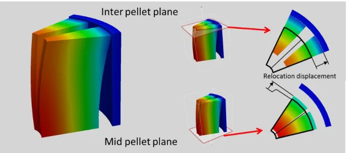
Thermal stresses induced by the temperature gradient under the first power increase will lead to the pellet fragmentation as it is assumed in the single pellet fragment model presented in section 3.1. The pellet fragment hourglass shape resulting of the mechanical equilibrium is shown in Figure 2. This hourglass shape leads to a first gap closure at the inter-pellet plane with lower temperatures in the pellet as shown in Figure 2. Compare to the un-fragmented pellet we can define a relocation radial displacement at inter and mid pellet planes (see Figure 2). At the mid pellet plane the radial relocation displacement is mainly due to the circumferential thermal expansion in the central zone of the pellet. For the inter pellet plane the axial curvature of the pellet fragment increases significantly the radial relocation displacement. The radial relocation displacement at the mid pellet plane can be compared to a uniform radial and circumferential strain field which can be in the range [0.5-0.8%] under nominal condition and can lead to a pellet cladding gap thickness reduction between 15 and 25%
Figure 2 : Pellet fragment hourglass shape and temperature at the end of the first power increase.
4.2 Central hole formation and associated fuel mass transfer
At the beginning of irradiation under SFR nominal power loading condition high temperatures lead to a fuel restructuration in the central part and the formation of a central hole [1]. The main mechanism involves in this restructuration phenomenon is a fuel mass transfer due the diffusion of a vapour phase through material porosities (see references [5] and [6]). A porosity diffusion model has been implemented in GERMINAL [1] in order to compute the fuel mass transfer and the size of the central hole under irradiation. In this paper a coupling mechanism between mass transfer and fuel relocation has been proposed according a kinematical assumption illustrated in Figure 3. In the latter we consider that the
fuel volume leaving the pellet centre is inserted between fragments in the columnar grain zone where the fuel has been restructured. This assumption is consistent with the idea that crack surfaces act as source of lenticular porosities needed for the mass transfer [6].
Figure 3 : Fuel mass redistribution and pellet fragment relocation during the central hole formation.
In the 3D fuel pin simulation a first simple modelling has been proposed in order to compute the radial relocation displacement due to fuel mass transfer according the kinematical assumption proposed in Figure 3.
First, GERMINAL results are post processed in order to compute the fuel volume transferred during the central hole formation (red surfaces in Figure 3). For each time step the fuel equivalent filling density can be derived from the porosity diffusion model of GERMINAL (see Figure 4). During the central hole formation this equivalent filling density will decrease in the centre of the pellet, and, according the mass balance equation, will increase for intermediate radii up to the maximal radius of the columnar grain zone. A radial integration of the negative part of the equivalent filling density variation between 𝑡 = 0 and the current time step gives the fuel volume leaving the central part (blue hatched area in Figure 4).
Figure 4 : Computation of the fuel volume transferred according 1D results of GERMINAL. Secondly, a displacement boundary condition is added in the 3D single fragment finite element model to compute the radial relocation displacement induced by the mass transfer. This boundary condition (see Figure 5) is defined on the free surface of the pellet fragment for the columnar grain zone (blue line in Figure 5) with a unilateral condition where 𝑒(𝑡) is the half thickness of the transferred volume between two pellet fragments at time 𝑡.
Figure 5 : Displacement boundary condition for the computation of the radial relocation displacement.
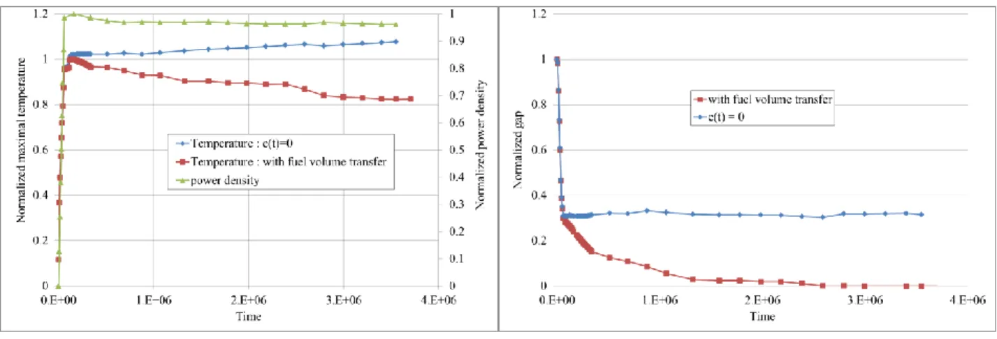
The results obtained in the 3D simulation are presented in a) Maximal fuel temperature b) Pellet- cladding gap
Figure 6 for fuel maximal temperature and pellet cladding gap closure. To illustrate the impact of the mass transfer a first computation has been achieved with a
parameter 𝑒(𝑡) equal to zero. As expected fuel volume transfer has a significant impact on the gap closure through the radial relocation displacement, we can see in a) Maximal fuel temperature b) Pellet- cladding gap
Figure 6 b) that the pellet cladding gap is closed at the end of irradiation compare to the case 𝑒(𝑡) = 0. Consequently a smaller gap leads to reduce the maximal fuel temperature of approximately 25% after an irradiation period of 45 days.
a) Maximal fuel temperature b) Pellet- cladding gap
Figure 6 : 3D simulation results: impact of the mass transfer on pellet- cladding gap closure.
5 Conclusions
In this work a 3D finite element model of the SFR fuel pin is proposed to study pellet-to-cladding gap closure mechanism at the beginning of irradiation. The 3D model represents a single pellet fragment and its associated piece of cladding. A nonlinear thermo-mechanical computation scheme has been developed and implemented in the LICOS code of the PLEIADES platform. Chemo-physical state variables are pre-computed with the GERMINAL code and are introduced in the 3D computation scheme as some input data through the irradiation loading and interpolation techniques.
Pellet-to-cladding gap closure mechanism has been studied under nominal irradiation conditions and the fuel radial relocation displacement, computed through an empirical approach in the 1D model, can be explicitly defined with 3D results. Two mechanisms have been identified to explain the radial relocation displacement. The first one, due to the hour glass shape of the pellet fragments under thermal strains, is linked to the magnitude of the thermal gradient in the pellet and can lead to a significant relocation displacement at the mid pellet plane under an increasing power level. The second mechanism is based on a coupling phenomenon with the fuel mass transfer occurring during the central hole formation. The kinematic assumption, proposed to compute the relocation displacement, considers that the central hole volume in inserted between pellet fragments in the columnar grain zone where the fuel has been restructured. A first computation, with a simplified description of the coupling phenomenon, shows that this mechanism can explain a complete closure of the gap at the beginning of irradiation during the central hole formation.
New developments are now in progress in order to propose a full coupling formulation between the porosity diffusion model and the radial relocation displacement model.
6 References
[1] Current status and progression of GERMINAL fuel performance code for SFR oxide fuel pins, M. Lainet and al., Proc of FR17, Yekaterinburg, Russian Federation, 2017
[2] Simulation of pellet-cladding interaction with the pleiades fuel performance software environment, B Michel and al., Nuclear Technology 182 (2), 124-137
[3] Licos, a fuel performance code for innovative fuel elements or experimental devices design, T Helfer and al., Nuclear Engineering and Design 294, 117-136
[4] http://www-cast3m.cea.fr/
[5] The kinetics of pore movement in UO2 fuel rods, P.F. Sens, Journal of Nuclear Materials,
43 (1972) 293-997.
[6] The movement of lenticular pores in mixed oxide (U,Pu)O2 nuclear fuel elements, C.F.


![[PDF] Cours programmation web avec php et MySQL | Télécharger PDF](data:image/gif;base64,R0lGODlhAQABAIAAAP///wAAACH5BAEAAAAALAAAAAABAAEAAAICRAEAOw==)