Publisher’s version / Version de l'éditeur:
Canadian Acoustics, 28, 3, pp. 12-13, 2000-09-01
READ THESE TERMS AND CONDITIONS CAREFULLY BEFORE USING THIS WEBSITE.
https://nrc-publications.canada.ca/eng/copyright
Vous avez des questions? Nous pouvons vous aider. Pour communiquer directement avec un auteur, consultez la première page de la revue dans laquelle son article a été publié afin de trouver ses coordonnées. Si vous n’arrivez pas à les repérer, communiquez avec nous à [email protected].
Questions? Contact the NRC Publications Archive team at
[email protected]. If you wish to email the authors directly, please see the first page of the publication for their contact information.
Archives des publications du CNRC
This publication could be one of several versions: author’s original, accepted manuscript or the publisher’s version. / La version de cette publication peut être l’une des suivantes : la version prépublication de l’auteur, la version acceptée du manuscrit ou la version de l’éditeur.
Access and use of this website and the material on it are subject to the Terms and Conditions set forth at
Power balance methods to estimate junction attenuation in lightweight
constructions
Nightingale, T. R. T.; Bosmans, I.
https://publications-cnrc.canada.ca/fra/droits
L’accès à ce site Web et l’utilisation de son contenu sont assujettis aux conditions présentées dans le site LISEZ CES CONDITIONS ATTENTIVEMENT AVANT D’UTILISER CE SITE WEB.
NRC Publications Record / Notice d'Archives des publications de CNRC:
https://nrc-publications.canada.ca/eng/view/object/?id=6356e27d-7a12-41f9-96bd-d7ec627203c9 https://publications-cnrc.canada.ca/fra/voir/objet/?id=6356e27d-7a12-41f9-96bd-d7ec627203c9
POWER BALANCE METHODS TO ESTIMATE JUNCTION ATTENUATION IN
LIGHTWEIGHT CONSTRUCTIONS
Trevor RT Nightingale, Ivan Bosmans
Institute for Research in Construction, National Research Council, Ottawa, Ontario, Canada K1A OR6
Canadian Acoustics, 28, (3), Proceedings of the Acoustics Week in Canada (Sherbrooke, Québec, 9/28/2000), pp. 12-13, September 01, 2000
RÉSUMÉ -
Disponible aussi tôt que possible.
INTRODUCTION
In-situ junction attenuation is an important factor in determining the relative importance of structure borne flanking paths in buildings. Unfortunately, junction attenuation can not be measured directly and must be measured indirectly. Traditionally, this has been done using power balance methods, such as SEA, where measures of velocity level difference, VLD, between the two connected surfaces are related to the attenuation of the junction connecting them. For surfaces that are homogeneous, isotropic and lightly damped, such as cast-in-place concrete, this method has proven to be very effective.
This summary paper will assess the suitability the power balance method to estimate junction attenuation in a lightweight-framed construction by investigating the sensitivity of the measured VLD to the choice of measurement positions and by relating the variance in these measures to attenuation with distance in the surfaces.
THEORY – RELATING VLD TO JUNCTION ATTENUATION
The junction attenuation, in decibels, between two coupled plates can be expressed in terms of measurable properties, namely the VLD (term in first brackets) and the total loss factor η,
ú û ù ê ë é + ú ú û ù ê ê ë é = 1 2 1 2 1 2 2 2 1 2 1 12 10log 10log S L C m m v v R g surface surface ωπ η (1)
where m is the mass of the surface, v is the measured mean surface velocity, Cg is the group speed for bending waves, S is the plate area and L is the length of the junction. Theoretically, Eqn. 1 is valid only when the following conditions [1] are satisfied:
1.) The source plate must be sufficiently large to support many modes in each third octave band and should be moderately damped. These two requirements can be expressed by a single
expression: the modal overlap factor which should exceed unity;
2.) The reverberation radius should be very small, i.e., the plate is lightly or moderately damped. This ensures that accelerometer positions located even a short distance from the source will be sampling the reverberant field. A highly damped plate has a large reverberation radius which is characterised by strong attenuation with distance from the source;
3.) Each of the surfaces must be homogeneous and isotropic thereby assuring that each surface is a single subsystem and that the energy will be sampled only in that subsystem. Also, the coupling must be sufficiently weak, and the damping of the receive system sufficiently great, that there will be a difference in the modal energies of the two surfaces.
Eqn. 1 may be considered to be approximate for surfaces that are orthotropic since it is assumed that the group speed is independent of the direction of propagation. This difficulty does not effect the linear dependence of junction attenuation on the VLD. For the cases and frequencies presented here, the modal overlap factor exceeded unity.
MEASURED VELOCITY LEVEL DIFFERENCE
The measurement method proposed by Craik[2] was used to estimate the VLD between the gypsum board wall and the subfloor surface of the wood-framed floor assembly shown in Figure 1. It is important to note the orientation of the framing members in the two surfaces as this determines the orientation of the butt joints between the sheathing panels. In the floor, the 38x235 mm solid wood joists, spaced 400 mm o.c., are parallel to the wall/floor junction so the 1.2x2.4 m sheathing panels are oriented with the short axis and butt joints parallel to the junction. The long side of the
panel joins to adjacent panels using interlocking tongue and groove joints. The 1.2x2.4 m gypsum board panels do not have a profile on the edges and the butt joints are oriented perpendicular to the wall/floor junction. Heavy dashed lines indicate the butt joints between panels.
P a rt it io n Wa ll Flo o r 4.54 m 2. 3 2 m 4. 2 0 m
Figure 1: Accelerometer locations for VLD
measurements the between the wall and the subfloor are shown by solid symbols. Positions used for the draw-away measurements are shown by the open symbols, while the source is indicated by the solid rectangle.
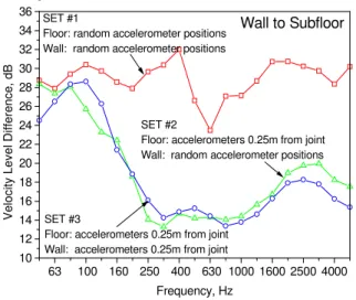
If, on average, Conditions 1, 2 and 3 are satisfied then the measured VLD should be reasonably insensitive to the location of the accelerometer positions with the largest change occurring in the low frequencies where there are fewer modes. Position sensitivity was investigated by measuring the wall/floor junction using three sets of accelerometer positions. In Set 1 the accelerometers were randomly located on both the wall and subfloor (shown in Figure 1 by the triangles on the wall and the circles on the subfloor). In Set 2 the accelerometers on the subfloor were moved toward the wall and located 0.25±0.07 m from the junction (and are shown by the squares). The wall positions were unchanged. In Set 3 both the wall and subfloor accelerometers were located 0.25±0.07 m from the junction. (Pentagonal symbols show the positions on the wall).
Comparing Set 1 and Set 2 data of Figure 2 it can be seen that the measured VLD is very sensitive to the
measurement location on the subfloor. The change in VLD was greater than 10 dB for frequencies above 200 Hz. However, comparing Sets 2 and 3, it can be seen that there was virtually no change in the measured VLD as a result of moving the wall accelerometers close to the junction. The marked drop in the measured VLD caused by moving the positions on the floor closer to the junction suggests that the vibration field is highly attenuated as it propagates in the subfloor. This suggests that Conditions 2 and/or 3 have not been satisfied and is the subject of the next section.
63 100 160 250 400 630 1000 1600 2500 4000 10 12 14 16 18 20 22 24 26 28 30 32 34 36 Wall to Subfloor SET #3
Floor: accelerometers 0.25m from joint Wall: accelerometers 0.25m from joint
SET #2
Floor: accelerometers 0.25m from joint Wall: random accelerometer positions
Frequency, Hz Vel o c ity Lev e l D iffer enc e, dB SET #1
Floor: random accelerometer positions Wall: random accelerometer positions
Figure 2: Measured VLD between the wall and subfloor for three different sets of accelerometer positions as shown in Figure 1.
VIBRATION RESPONSE OF THE SUBFLOOR SURFACE
Measurements of surface acceleration were made along a line perpendicular to the joint to see if Conditions 2 and 3 were satisfied.
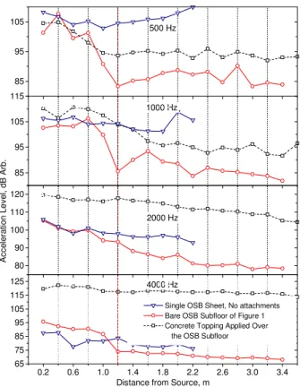
From examination of the acceleration levels with distance shown in Figure 3 for the bare OSB subfloor of floor/ceiling assembly, it is evident that the vibration response is not uniform. There are two distinct regimes. One close to the source where there is strong localisation of energy and one further away where the level decreases with distance (a violation of Condition 2). This is particularly evident when compared to the very gradual change in response observed for single OSB sheet without attachments. The transition between the two regions in the floor/ceiling assembly with the bare subfloor occurs 1.2 m from the source where there is a butt joint in the OSB sheathing (as shown in Figure 1).
Obviously the discontinuity in the vibration levels at a butt joint between the subfloor panels precludes treating the OSB subfloor surface as a single subsystem (a violation of Condition 3). These observations indicate that the presence of butt joints, joists and increased in-situ damping prevent a diffuse field in a framed floor [3].
Figure 3, which also shows the vibration response of the same floor when covered by a 38 mm layer of 2000 kg/m3 concrete, indicates that a topping may reduce localisation of energy near the source. At 4 kHz the vibration response is quite uniform across the floor while at 500 and 1000 Hz there is still considerable localisation of energy near the source. Localisation increases with decreasing frequency.
It is interesting to note that at 4 kHz the rate of attenuation in the OSB subfloor after the butt joint is comparable to those observed for a single OSB sheet without attachments. At this frequency the coupling between the OSB and the joists is quite weak since the fasteners appear as individual points (rather than line-connected) and the dominant attenuation mechanism may be internal losses in the OSB. With the concrete topping the bending wavelength will increase and so too will the frequency at which the joists appear point-connected and one might expect greater localisation. However, this is not the case and can be explained by recognising that the effect of rotary inertia of the joists will diminish as the stiffness and mass of the floor surface increases. Also, the topping will act as a bridge across the butt joint. Thus, with the topping the joists might be line-connected but their effect is greatly reduced compared to the case with the bare floor. The rate of attenuation with or without the topping is similar for distances after the butt joint (i.e., greater than 1.6 m) indicating that the loss mechanism is likely the same for both situations. 0.2 0.6 1.0 1.4 1.8 2.2 2.6 3.0 3.4 65 75 85 95 105 115 125 4000 Hz A c c e le ra ti on Le v e l, dB Ar b.
Distance from Source, m
0.2 0.6 1.0 1.4 1.8 2.2 2.6 3.0 3.4 80 90 100 110 120 2000 Hz
Single OSB Sheet, No attachments Bare OSB Subfloor of Figure 1 Concrete Topping Applied Over the OSB Subfloor
0.2 0.6 1.0 1.4 1.8 2.2 2.6 3.0 3.4 85 95 105 115 1000 Hz 0.2 0.6 1.0 1.4 1.8 2.2 2.6 3.0 3.4 85 95 105 500 Hz
Figure 3: Measured third-octave band vibration response of the floor surface in a direction perpendicular to the joists. The dashed line at 1.2m from the source indicates the location of the butt joint between the OSB sheets. Shown for comparison is the response of a sheet of OSB without any attachments.
CONCLUSIONS
The measured VLD’s shown in Figure 2 are the result of two attenuation mechanisms: the wall/floor junction and losses in the measurement surfaces. Additional attenuation in the surfaces, which is a complex function of the damping, size and spacing of the joists, presence of joints in the sheathing, will tend to increase the measured VLD and make the measurements very sensitive to accelerometer location. The most important factor appears to be the butt joints in the OSB subfloor. The effect of which is greatly reduced if the surface is covered by concrete. Further work is needed to determine a suitable in-situ test method for lightweight framed constructions.
REFERENCES
1.) T.R.T. Nightingale, Ivan Bosmans, “Estimating Junction Attenuation in Lightweight Constructions,”
Proceedings of INTERNOISE 2000, Nice France, August 28-30, 2000.
2.) R.J.M. Craik, Applied Acoustics, Vol. 15, pp. 355-361, 1981.
3.) T.R.T. Nightingale, Ivan Bosmans, Building Acoustics, Vol. 6, No.3/4, pp. 269-288, 1999.