Publisher’s version / Version de l'éditeur:
Cement and Concrete Composites, 26, February 2, pp. 163-174, 2004-02-01
READ THESE TERMS AND CONDITIONS CAREFULLY BEFORE USING THIS WEBSITE.
https://nrc-publications.canada.ca/eng/copyright
Vous avez des questions? Nous pouvons vous aider. Pour communiquer directement avec un auteur, consultez la
première page de la revue dans laquelle son article a été publié afin de trouver ses coordonnées. Si vous n’arrivez pas à les repérer, communiquez avec nous à PublicationsArchive-ArchivesPublications@nrc-cnrc.gc.ca.
Questions? Contact the NRC Publications Archive team at
PublicationsArchive-ArchivesPublications@nrc-cnrc.gc.ca. If you wish to email the authors directly, please see the first page of the publication for their contact information.
NRC Publications Archive
Archives des publications du CNRC
This publication could be one of several versions: author’s original, accepted manuscript or the publisher’s version. / La version de cette publication peut être l’une des suivantes : la version prépublication de l’auteur, la version acceptée du manuscrit ou la version de l’éditeur.
For the publisher’s version, please access the DOI link below./ Pour consulter la version de l’éditeur, utilisez le lien DOI ci-dessous.
https://doi.org/10.1016/S0958-9465(03)00085-4
Access and use of this website and the material on it are subject to the Terms and Conditions set forth at
Optimization of the type and amount of polypropylene fibres for
preventing the spalling of lightweight concrete subjected to
hydrocarbon fire
Bilodeau, A.; Kodur, V. K. R.; Hoff, G. C.
https://publications-cnrc.canada.ca/fra/droits
L’accès à ce site Web et l’utilisation de son contenu sont assujettis aux conditions présentées dans le site LISEZ CES CONDITIONS ATTENTIVEMENT AVANT D’UTILISER CE SITE WEB.
NRC Publications Record / Notice d'Archives des publications de CNRC:
https://nrc-publications.canada.ca/eng/view/object/?id=31f6f0bd-39cc-421c-87dc-ca960aafa524 https://publications-cnrc.canada.ca/fra/voir/objet/?id=31f6f0bd-39cc-421c-87dc-ca960aafa524
Optimization of the type and amount of polypropylene
fibres for preventing the spalling of lightweight
concrete subjected to hydrocarbon fire
Bilodeau, A.; Kodur, V.K.R.; Hoff, G.C.
NRCC-45687
A version of this document is published in / Une version de ce document se trouve dans :
Cement and Concrete Composites, v. 26, no. 2, Feb. 2004, pp. 163-174
OPTIMIZATION OF THE TYPE AND AMOUNT OF POLYPROPYLENE FIBRES FOR PREVENTING THE SPALLING OF LIGHTWEIGHT CONCRETE
SUBJECTED TO HYDROCARBON FIRE
A. Bilodeau,a,*, V.K.R. Kodur b and G.C. Hoff c
a
CANMET, Natural Resources Canada, 405 Rochester St., Ottawa, Canada, K1A 0G1.
b
IRC, National Research Council, M-59, Montreal Road, Ottawa, Canada, K1A 0R6
c
Hoff Consulting LLC, 250 Saddlewood Lane Clinton, MS 39056, U.S.A.
Abstract
This paper presents the results from an experimental study on the optimum amount of polypropylene fibres to be used in lightweight high-strength concrete to prevent spalling when exposed to hydrocarbon fire, taking into consideration the characteristics of the lightweight aggregate, the water-to-cement ratio (W/C) of the mixtures, and the length and thickness of the fibres.
Twelve different concrete mixtures were made. One block, 610x425x770 mm in size, was cast from each mixture and tested for fire resistance under hydrocarbon fire exposure. The temperature in the blocks during the test was recorded. After the test, the condition of the blocks was evaluated, and cores were taken for determining the residual compressive strength of the concrete.
Results from the study show that close to 3.5 kg of the 20-mm polypropylene fibres per cubic meter of concrete is required to prevent the spalling of a low W/C lightweight concrete made with a silica fume-blended cement when subjected to hydrocarbon fire but that only 1.5 kg of the finer 12.5-mm fibres per cubic meter is sufficient.
The amount of 20-mm fibres required to prevent spalling for a higher W/C of 0.42 is significantly less: of the order of 1.5 kg per cubic meter of concrete.
The susceptibility of the concrete to spalling increases with the degree of absorption of the lightweight aggregate used in concrete.
Keywords: High-strength concrete; Hydrocarbon fire; Lightweight concrete; Polypropylene fibres
1. Introduction
Several investigations performed at various international organizations (1-4), and work performed at CANMET and NRC (5 ,6) have shown that the use of polypropylene fibres in concrete considerably reduces the amount of spalling of the concrete exposed to hydrocarbon fire. It has also
been shown that the amount of spalling is a function of the density of the matrix (W/C), type and amount of lightweight aggregate in the concrete, and of the type, thickness and length of the fibres. The objective of this study was to determine the optimum amount of polypropylene fibres to be used in the lightweight concrete to prevent spalling when it is exposed to hydrocarbon fire, taking into consideration the characteristics of the lightweight aggregate, the water-to-cement ratio (W/C) of the mixtures, and the length and thickness of the fibres.
2. Scope
Twelve different concrete mixtures were made, using two lightweight aggregates; a low-absorption, and a high-absorption aggregate (see Table 1 for details). The low-absorption aggregate was used in two different conditions, dry and saturated, to determine if this had an effect on the fire resistance. Ten of the mixtures were high-strength, low W/C mixtures, whereas two mixtures were made using a higher W/C to determine the effect of the density of the concrete matrix on the spalling resistance and the optimum fibre content. Varying amounts of two different fibres were used in the concrete mix. Most mixtures were made with the same fibres that were used in the previous CANMET studies (5, 6), whereas three mixtures were made with a shorter and finer fibre to determine how this would affect the fire resistance.
One block, 610x425x770 mm in size, was cast from each mixture and tested for fire resistance under hydrocarbon fire exposure. Concrete cylinders were also cast to determine the compressive strength of the concrete. The temperature in the blocks during the test was recorded. After the test, the condition of the blocks was evaluated, and cores were taken for determining the residual compressive strength of the concrete.
The concrete mixing, casting of the blocks, visual evaluation of the blocks after fire exposure, the coring and compressive strength testing were performed at CANMET, whereas the hydrocarbon fire resistance experiments were performed at the Institute for Research in Construction (IRC) of the National Research Council of Canada (NRC).
3. Materials
The materials used in this program are described below. 3.1. Portland cement
A silica fume-blended portland cement was used in this study. The cement was from the same producer as that used in the previous CANMET studies (5, 6). The silica fume content of the cement was about 8 per cent.
3.2. Fine aggregate
The fine aggregate was a natural sand that was used in a dry condition. The specific gravity of the sand was 2.70 and its absorption was 0.8 per cent.
3.3. Coarse aggregate
Two different coarse lightweight aggregates were used; one having a low-absorption of 5.2% and a second aggregate having a higher absorption of 14.4%. The low-absorption aggregate was an expanded slate from North Carolina, U.S.A., and had a specific gravity of 1.56. The high-absorption aggregate was an expanded slate from New York state, U.S.A., and had a specific gravity of 1.57. The grading of both aggregates was in accordance with ASTM C 330 Standard Specification for Lightweight Aggregates for Structural Concrete.
Two different types of commercially-available polypropylene fibres were used. The first type was fibrillated, multi-dimensional fibres, 20-mm maximum length, and was the same type as the fibres used in the previous CANMET studies (5, 6). The second type was multifilament fibres, 12.5- mm in length. The second type of fibre also appeared significantly thinner than the first one.
3.5. Superplasticizer
A commercially-available sulphonated, naphthalene formaldehyde condensate superplasticizer was used in all the mixtures. This superplasticizer is available as a dark brown 40 per cent solid aqueous solution.
4. Concrete mixtures
The proportioning of the concrete mixtures is summarized in Table 1. A total of twelve non-air entrained lightweight concrete mixtures was made in this study. Ten mixtures were made with a low W/C of 0.33 whereas two mixtures had a W/C of 0.42. Five mixtures were made with the low-absorption coarse lightweight aggregate. The low-absorption aggregate was used in a dry condition except for one mixture (No. 3) for which the aggregate was purposely saturated prior to mixing. The seven remaining mixtures were made with the high-absorption coarse lightweight aggregate which was used in a semi-saturated condition; about 10% moisture content.
Two different amounts of both fibres, 1.5 and 2.5 kg per cubic meter of concrete, were used in the mixtures made with the low-absorption aggregate. Three different amounts of the 20-mm fibres, 1.5, 2.5, and 3.5 kg per cubic meter of concrete, and 1.5 kg of the 12.5-mm fibres per cubic meter of concrete, were used in the low W/C mixtures made with the high-absorption aggregate. The two mixtures having a higher W/C of 0.42 were made with the high-absorption aggregate, and incorporated 1.5 and 2.5 kg of fibres per cubic meter of concrete. In addition, one mixture without fibres was made with the high-absorption aggregate.
The concrete mixtures were made in a laboratory pan mixer, and the mixing time was 6 minutes. The properties of the freshly-mixed concrete are also given in Table 1. Higher slumps in the range of 120 to 180-mm were used for the first five mixtures. It was then felt that slumps in that range were not necessary to properly cast the concrete blocks and therefore lower slumps in the range of 60 to 110-mm were used thereafter. The dosage of superplasticizer increased with the increased amount of fibres in the mixtures. The unit weight of the mixtures ranged from 1935 to 1992 kg/m3, and the entrapped air content from 1.8 to 3.0%.
5. Preparation, casting and curing of test specimens
The main specimen cast from each mixture was a 610x425x770-mm reinforced block as illustrated in Fig. 1 for the determination of the hydrocarbon-fire resistance. Vertical and horizontal reinforcing bars were 20-mm bars, and the ties were made of 10-mm bars. The concrete cover on the steel was 50-mm. In addition to the block, 102x203 mm cylinders, nine from mixtures 1 to 9, and three from mixtures 10 to 12, were cast for compressive strength determination.
The blocks and the cylinders were cast in two layers, with each layer being consolidated using an internal vibrator for the blocks and a vibrating table for the cylinders. After casting, the specimens were covered with plastic sheets and water-saturated burlap, and were left in the casting room for 24 hours. The cylinders were then demoulded and transferred to the moist-curing room at 23 ± 1.7°C and 100 percent relative humidity until required for testing. The forms on the blocks were removed after 24 hours, and the blocks were then covered with wet burlap for six additional days. Following this moist curing period, the blocks were left in air at room temperature at about 50% relative humidity until required for testing.
6. Testing of specimens
The nine cylinders from mixtures 1 to 9 were tested in compression at the ages of 7, 28 and 91 days, and the three cylinders from mixtures 10 to 12 were tested in compression at 28 days.
Between 12 and 13 weeks after casting, the blocks were transported to the IRC Laboratory, Ottawa, to be tested for the hydrocarbon fire resistance. Before the test, the blocks had all their faces except one covered with insulating material to protect them against the fire as shown in Fig. 2. Two fire-resistance tests were performed by exposing the concrete blocks (six blocks per test) to hydrocarbon fire for a period of two hours in accordance with ISO 834 standard.
During the fire test, the temperature was recorded at various locations in the concrete blocks using thermocouples. After the fire test, the blocks were allowed to cool down in the furnace with the door open and the ventilation system working for a few hours. The blocks were then taken out from the furnace and left in the laboratory. Following this, the blocks were examined visually, photographs were taken, and measurements of the depth of spalling on the exposed face at 50-mm intervals were made. The blocks were then transported to the CANMET laboratory where cores were taken, and then tested for compressive strength.
7. Discussion of test results
7.1. Compressive strength of cylinders
For the concrete made with the low-absorption aggregate, the compressive strength at 28 days ranged from 62.0 to 67.9 MPa, and was slightly higher at 91 days ranging from 64.9 to 70.8 MPa (Table 2). The concrete made with the high-absorption aggregate and having the same W/C showed slightly lower compressive strengths at both ages with values ranging from 56.5 to 62.8 MPa at 28 days, and from 59.1 to 64.6 MPa at 91 days. The two mixtures made with a higher W/C showed slightly lower compressive strength at 28 days with values of 54.1 and 55.3 MPa, respectively.
7.2 Visual evaluation of blocks
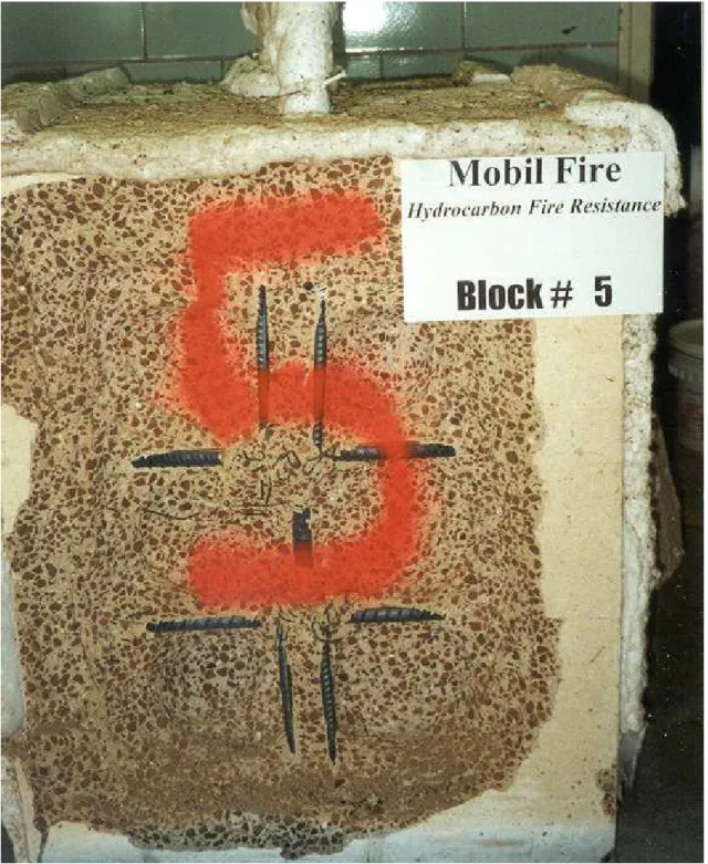
The photographs of various blocks, taken after hydrocarbon fire exposure, are shown in Figures 3-14.
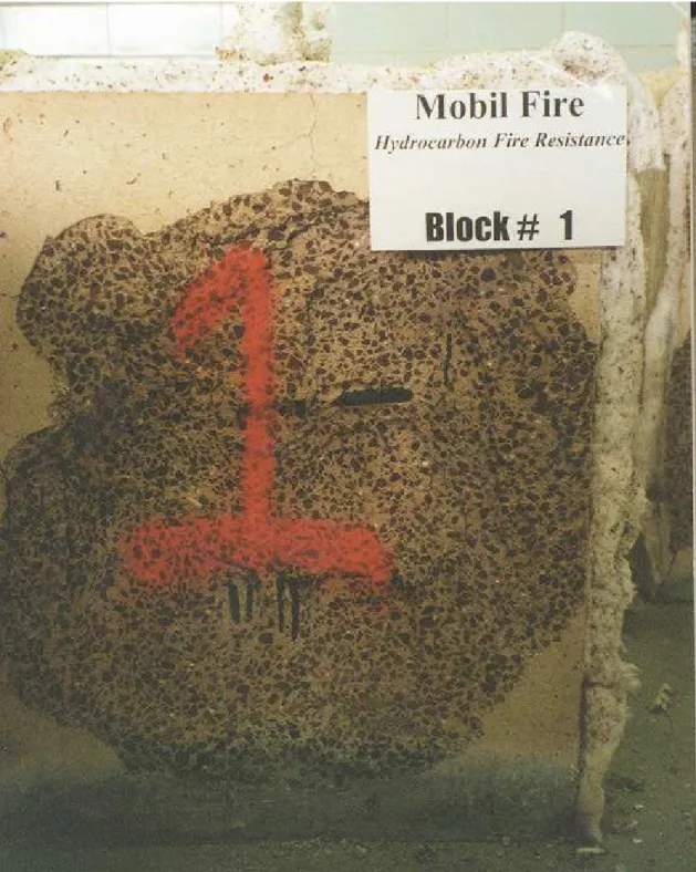
Block No. 5, made without fibres (Fig. 7) was very severely damaged, much more than any other block containing fibres. This was observed in previous investigations (5,6), and confirms that high-strength concrete without fibres is prone to severe spalling under hydrocarbon fire exposure.
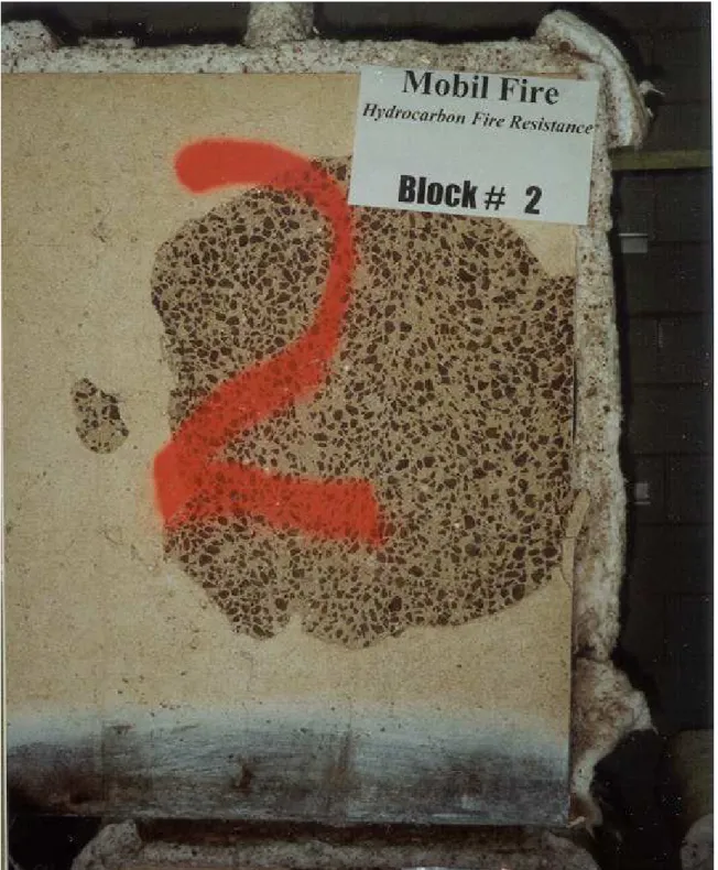
For the concrete made with the low-absorption aggregates, mixture No. 1 incorporating 1.5 kg of 20-mm fibres per cubic meter of concrete showed severe deterioration (Fig. 3), confirming the previous investigation that showed that this amount of fibres was not sufficient to totally prevent spalling during the fire test (6) . The use of 2.5 kg of 20-mm fibres (Block No.2) significantly reduced the deterioration but could not completely prevent spalling (Fig. 4). The use of lightweight coarse aggregates in a saturated condition instead of a dry one, did not noticeably affect the performance of the concrete; the condition of Block No. 3 (Fig. 5) being very similar to that of Block No.2 (Fig. 4). However, as shown in Fig. 6, the use of only 1.5 kg of 12.5-mm fibres (Block No. 4) totally prevented the spalling of the concrete. Block No. 12, shown in Fig. 14, and incorporating 2.5 kg of 12.5 mm fibres per cubic meter of concrete also showed no spalling at all. There are significantly more of the thinner 12.5-mm fibres per unit volume of concrete than of the 20-mm fibres, and this probably explains why they are more efficient than the latter for preventing the spalling of concrete exposed to the hydrocarbon fire test. The melting point of both types of fibres used in this study is not known but it is believed to be very similar. However, if this is not the case, this could also partly explain the relative performance of the two different types of fibres; a fibre with lower melting point would probably be more efficient to reduce the spalling of concrete exposed to fire.
For the concretes made with the high-absorption aggregate, Block No. 6, incorporating 1.5 kg of 20-mm fibres per cubic meter of concrete, also showed severe deterioration (Fig. 8); similar to that of the concrete made with the low-absorption aggregate, and incorporating the same amount of fibres (Block No. 1) shown in Fig. 3. The use of 2.5 kg of 20-mm fibres (Block No. 7) noticeably reduced the deterioration (Fig. 9), but not as much as it did for the concrete made with the low-absorption aggregate (Block No. 2, Fig. 4). This indicates that the higher the absorption of the aggregate the greater is the susceptibility of the concrete to spall when exposed to fire. It required as much as 3.5 kg of the 20-mm fibres (Block No. 8) to totally prevent the spalling of the concrete (Fig. 10). However, once again, the use of only 1.5 kg of the 12.5-mm fibres per cubic meter of concrete (Block No. 11) was sufficient to prevent the spalling of the concrete (Fig. 13), and this confirmed the efficiency of this type of fibre for protecting the concrete from spalling when exposed to fire.
The concrete made with the high-absorption aggregate, and at a higher W/C of 0.42 (Blocks No. 9 and 10) showed no spalling even with only 1.5 kg of the 20-mm fibres per cubic meter of concrete (Figs. 11 and 12). This demonstrated the much lower susceptibility to spall of high W/C concrete when exposed to fire, probably due to its less dense matrix compared to that of the low W/C concrete. Unfortunately, no fire resistance test was performed on the high W/C concrete without fibres to determine whether or not those were needed for this type of concrete. After a literature survey, Lindgård and Hammer stated that the W/C of lightweight concrete must be at least higher than 0,40, otherwise the concrete will show spalling when exposed to fire (7). In this study, the highest W/C was 0.42, which is close to 0.40, and in addition to this, a silica fume-blended cement was used. Therefore, it is very difficult to speculate what would have been the behavior of this concrete without fibres when exposed to the hydrocarbon fire test.
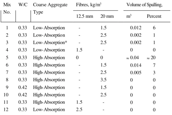
7.3 Volume of spalling
The estimated volume of spalling for each block is given in Table 3. The block made without fibres (No. 5) was very severely damaged, and it was very difficult to properly determine the amount of spalling; the best estimate was 0.04 cubic meter, or 20%, much higher than any other block.
The values of spalling confirm satisfactorily the visual evaluation of the blocks. The use of up to 2.5 kg of the 20-mm fibres was not enough to prevent the spalling of the low W/C concrete made with both the low and high-absorption aggregates. The values of the volume of spalling confirm that the concrete made with the high-absorption aggregate was more susceptible to the spalling than the concrete made with the low-absorption aggregate; the latter showed about 14 and 60 percent less spalling than the former for fiber contents of 1.5 and 2.5 kg per cubic meter of concrete, respectively. The measured values of spalling also confirm that the use of the low-absorption lightweight coarse aggregate in a saturated condition instead of a dry condition did not signifcantly affect the fire resistance of the concrete.
7.4 Temperature in the blocks during the fire test.
Figure 15 shows the temperature in the furnace during the hydrocarbon-fire resistance test. It illustrates the very rapid increase in the temperature that goes from room temperature to 1000
°
C in less than 10 minutes.When spalling occurred, it started very shortly after the beginning of the test, in less than five minutes, and this could be noticed from the sound produced by the spalling process. Also, most of the spalling occurred early in the test; usually in the first 20 minutes, approximately. This rapid spalling process is reflected by the temperature curves of the blocks. The temperatures recorded at 50-mm from the exposed faces of the three blocks that were the most severely damaged (Blocks No. 1, 5, and 6) were very similar to that of the furnace (Figs. 15, 16, 20 and 21) except that the maximum temperature was reached approximately 10 minutes later; the time required for the 50-mm concrete cover to spall and expose the thermocouple. This means that for those blocks, the first layer of steel was exposed directly to the fire approximately 20 minutes after the beginning of the fire test. However, for these blocks, the temperature at 100 mm from the exposed face did not increase much; it reached approximately 100 to 150
°
C.The three other mixtures that showed some deterioration (Blocks No . 2, 3, and 7) did not show a very high temperature at 50-mm, as shown in Figs. 17, 18 and 22. In fact, the temperature recorded at 50-mm in Blocks No. 2 and 3 was similar to that of the blocks that showed no spalling; maximum temperature ranging from about 200 to 300
°
C. This is due to the fact that for these two blocks, the concrete located in front of the thermocouples did not spall at all, or very marginally. However, Block No. 7 showed a slightly higher maximum temperature, approaching 400°
C. For this latter block, there was some spalling over almost the whole area of the exposed face, and this reduced the concrete cover for the thermocouples. Once again, the temperature at 100-mm in Blocks No. 2, 3 and 7 did not increase much, reaching about 100°
C.The blocks that showed no spalling (Blocks No. 4, 8, 9, 10, 11 and 12) showed maximum temperatures ranging from about 200 to 300
°
C at a depth of 50-mm, and of approximately 100°
C at 100 mm as shown in Figs. 19, 23, 24, 25, 26 and 27. The range of temperature at 50-mm is possibly due to the different thermal conductivity and specific heat of the various concretes, but more probably to slight differences in the thickness of the concrete cover on the thermocouples.7.5 Compressive strength of cores
After the fire test, cores were taken from the middle of the blocks, tested for compressive strength determination, and the results are given in Table 4. The compressive strength of the cores from the blocks made with the low W/C ranged from 48.4 to 60.2 MPa. The cores from the two blocks made with the W/C of 0.42 showed strengths of 50.5 and 53.7 MPa, respectively. In general, the compressive strength of the cores is higher than that of the cylinders at 7 days, but lower than that of the cylinders tested at 28 days. The actual strength of the concrete in the blocks at the time of the fire test is not known. Nevertheless, it seems that, given the level of strength of the cores,
the concrete in the middle of the blocks was not significantly affected by the fire test. This is in line with the relatively low temperature recorded at 100 mm from the exposed face, and confirms the results from a previous study (6).
8. Conclusions
Based on the results from this study, it appears that close to 3.5 kg of the 20-mm polypropylene fibres per cubic meter of concrete is necessary to prevent the spalling of a low W/C lightweight concrete made with a silica fume -blended cement when subjected to hydrocarbon fire.
The amount of 20-mm fibres to prevent spalling for a higher W/C of 0.42 is significantly less; of the order of 1.5 kg per cubic meter of concrete.
The susceptibility of the concrete to spall increases with the degree absorption of the lightweight aggregate.
The finer 12.5-mm fibres are significantly more efficient than the 20-mm fibres for preventing the spalling of the concrete exposed to fire. It appears that 1.5 kg per cubic meter was sufficient for the low W/C concrete.
Acknowledgments
This study was a joint project by ICON/CANMET/Natural Resources Canada, Mobil Technology Company, and the Institute for Research in Construction of the National Research Council of Canada. The polypropylene fibres were graciously provided by Synthetic Industries-Fibermesh Division.
6. Bilodeau, A., Malhotra, V.M. and Hoff, G.C. Hydrocarbon Fire Resistance of High-Strength
Normal-Weight and Lightweight Concretes Incorporating Polypropylene Fibres” Proceedings,
International Symposium on High-Performance and Reactive Powder Concretes. Editors: P.-C.
Aïtcin and Y. Delagrave, Sherbrooke, Canada, August 1998, pp. 271-296.
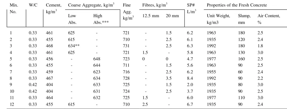
Table 1 - Proportions of the Concrete Mixtures and Properties of the Fresh Concrete
Coarse Aggregate, kg/m3 Fibres, kg/m3 Properties of the Fresh Concrete Mix. No. W/C Cement, kg/m3 Low Abs. High Abs.*** Fine Agg. kg/m3 12.5 mm 20 mm SP# L/m3 Unit Weight, kg/m3 Slump, mm Air Content, % 1 2 3 4 5 6 7 8 9 10 11 12 0.33 0.33 0.33 0.33 0.33 0.33 0.33 0.33 0.42 0.42 0.33 0.33 461 455 468 461 456 455 459 467 404 404 464 455 625 615 634** 625 - - - - - - - 615 - - - - 648 644 623 634 633 631 632 - 721 710 731 721 723 711 716 728 725 724 725 710 - - - 1.5 0 - - - - - 1.5 2.5 1.5 2.5 2.5 - 0 1.5 2.5 3.5 1.5 2.5 - - 6.2 6.1 6.3 5.8 4.7 5.6 6.2 8.4 2.0 3.7 6.0 6.7 1963 1935 1992 1963 1977 1963 1955 1992 1935 1935 1977 1935 180 120 180 130 160 90 60 90 80 90 110 90 2.5 2.4 1.8 3.0 2.5 2.5 2.4 2.2 3.0 2.5 3.0 2.4