HAL Id: hal-01743916
https://hal.insa-toulouse.fr/hal-01743916
Submitted on 26 Mar 2018
HAL is a multi-disciplinary open access
archive for the deposit and dissemination of
sci-entific research documents, whether they are
pub-lished or not. The documents may come from
L’archive ouverte pluridisciplinaire HAL, est
destinée au dépôt et à la diffusion de documents
scientifiques de niveau recherche, publiés ou non,
émanant des établissements d’enseignement et de
Mechanical behaviour of ancient masonry
Nathalie Domede, Gérard Pons, Alain Sellier, Youssef Fritih
To cite this version:
Nathalie Domede, Gérard Pons, Alain Sellier, Youssef Fritih. Mechanical behaviour of ancient
ma-sonry. Materials and Structures, Springer Verlag, 2009, 42 (1), pp.123-133.
�10.1617/s11527-008-9372-z�. �hal-01743916�
Mechanical behaviour of ancient masonry
N. Domède, G. Pons, A. Sellier, Y. Fritih
Laboratoire Matériaux et Durabilité des Constructions, Génie Civil INSA-UPS, 135 av. de Rangueil, 31077 Toulouse Cedex, France
Email: [email protected]
Abstract
The aim of this research was to build a behaviour law for ancient masonry made during the 19th century with
bricks and lime mortar bonds. This work should be of interest to researchers involved in the study of ancient masonry structures like arch bridges built in this period. To assess the masonry capacity vaults to support service loads and to determine their collapse loads, engineers need mechanical behaviour laws for their component parts. This experimental research was performed to explore the behaviour of the bricks, of the lime mortar, and of a wall until their failure in compression. In parallel the bricks / mortar interface criterion failure under shear and tensile load is characterised. After laboratory tests, numerical simulations were carried out using a finite element method (FEM) to define an homogenised behaviour law for a macro element including bricks and lime mortar bonds. In this goal, a behaviour law was firstly found for each component and then for the masonry as a whole by a FEM homogenisation process, including the non-linear behaviour domain up to the compression failure. The tension failure being reported into an interface element for which the failure criterion was adjusted on specific tests.
Key words: masonry, brick, mortar, lime, macro element, interface element.
Résumé
Le but de cette recherche est de construire une loi de comportement mécanique pour les maçonneries anciennes
faites de briques et de mortier de chaux construites pendant la deuxième moitié du 19è siècle. Ce travail intéresse les
chercheurs impliqués dans l’étude des ouvrages anciens en maçonnerie tels que les ponts voûtes construits à cette époque. Pour évaluer la capacité portante des voûtes en maçonnerie et leur charge de rupture, les ingénieurs ont besoin de connaître les lois de comportement mécanique de chacune des maçonneries constitutives. Une recherche expérimentale est entreprise pour déterminer le comportement en compression des briques, du mortier de chaux, d’un élément de mur. Parallèlement l’interface entre les briques et les joints de mortier est caractérisée vis-à-vis des sollicitations de traction et cisaillement. A l’issue des essais, des simulations numériques sont réalisées à l’aide de la méthode aux éléments finis dans le but de proposer une loi de comportement homogénéisée pour les maçonneries de brique travaillant en compression. Un critère de rupture d’interface est également proposé pour décrire la rupture en traction-cisaillement et compléter ainsi la loi homogénéisée pour la compression.
1 Introduction
The safety assessment of masonry vaults requires the mechanical behaviour of ancient masonries made up of bricks or stones and mortar to be known. The research described in this paper aims to collect data usable for non linear FEM analysis of the bridge. An illustration of such a FEM application has been carried out to analyse a masonry arch bridge, built in 1870 near Toulouse, in the South West of France (Domède [6]).
A bibliographic revue yielded no information on the mechanical behaviour of this type of masonry or their constituent components, like the bricks made in this region of France. Only one recent paper was found about hydraulic lime mortar, written by Lanas [7].
Besides, research has been carried out to determine the behaviour of recent masonry built with new bricks (usually perforated or hollow bricks) and thin bonds of cement mortar. Lourenço [8] has determined 5 failure modes. This local approach can be used to study the behaviour of walls. In Cruz-Diaz's [3] work, vertical bonds were not mortared. He studied the global response of a wall under horizontal loads and proved that the non-linear behaviour of walls came from the non-linear behaviour of bonds then cracks in the bricks.
To calculate large masonry structures like arch bridges, it is necessary to consider homogenized macro-elements. Pande [10] has performed an elastic homogenization. Pegon and Anthoine [11] have built a model with damage theory and proved that vertical bonds cannot be ignored when modelling collapse behaviour. Cecchi and Sab [1 and
2] found an analytical formula to calculate the elastic parameters of masonry from the parameters of each component, blocks and bonds.
Our aim was to determine the behaviour of an ancient regional masonry in the linear and non-linear domains up to the compression strength on one hand, and to characterize the failure criterion in shear and tension of the interface between lime and brick on another hand. This splitting into the characterisation method derives from the modelling options adopted for the FEM analysis: two different finite element types associated in the bridge:
• Homogenized massive macro-elements with an elasto-plastic behaviour until the compressive strength
• Interface elements which describe the interface “brittle” failure criterion in shear and tension between mortar
and bricks.
These two element types positioned alternately in the geometry of the bridge, describe together the whole masonry behaviour (tensile failure in interface, elastic domain and non linear behaviour until compression strength in massive macro elements).
The work related herein includes experimental tests and numerical homogenisation results usable for a macro element. To be able to repeat the tests in the laboratory without damage for old structures, new materials similar to the ancient ones were selected based on an earlier historic research on mechanic material behaviour about mortar and
bricks used in South West of France during the 19th century (Domède [5]). These materials, manufactured according
to the ancient process are similar to the old ones, and are used for historical monument rehabilitation.
The mortar was tested just after its hardening (one and two months old) and after an accelerated ageing obtained by an accelerated carbonation procedure (equivalent to more than 100 years of exposition to an atmospheric carbon dioxide exposure). Mechanical models were calibrated according to the test results for each material individually, then for the brick-mortar composite. The homogenization of masonry was validated by numerical simulation of a real compression test (two months old). The compression tests used were uniaxial tests. The experimental procedures established by the RILEM [13] for concretes were applied. In particular, the elastic modulus, Poisson's ratio, and the compressive strength were found by tests on cylindrical samples according to document TC14 – CPC [14]. This procedure was also applied to bricks.
The shear and tension failure criterion of the interface, i.e. the contact surface between the bricks and the mortar joint (named the “interface”), was the subject of a specific study based on a Casagrande test box.
2 Study of lime mortar
2.1 Description of lime and experimental procedure
SOCLI NHL 3.5 lime was selected because it is a hydraulic lime without any additives. It is produced in the Pyrenees and is similar to the hydraulic lime used to build bridges in south-west France during the 19th century. It is made up of lime Ca(OH)2, calcite CaCO3 and silicate C2S (tab. 1).
The composition of the mortar was: 35kg of lime for 90 litres of dry sand (river sand), and 21 litres of water (it is the
ratio found in the bridge classified files. The lime was used at a rate of 400 kg/m3 of mortar. Two shapes of samples were
used: “traditional” samples 4*4*16cm3, and cylindrical samples 6cm in diameter and 12cm in height. In the aim of
approaching the working conditions of the mortars as soon as possible during the assembly of a wall, the samples were not vibrated. They were made in three layers, each rammed five times.
The mechanical tests on the 4*4*16cm3 samples were carried out at a constant speed of 0.5MPa/s and according
to the official procedure for concrete. The tests took place at 7, 28, 60, 75, 170, 254 days and after accelerated ageing
(6 samples at each date). The tests on the 6*12cm2 cylinders were done at 1 month and 2 months, then after
accelerated ageing (6 samples). This artificial ageing of the samples was obtained as follows: the samples were placed in
an accelerated carbonation enclosure (temperature 22° ± 1°, relative humidity 68% ± 3%, partial pressure of CO2 = 50% of
atmospheric pressure) for 5 weeks, the time necessary for an almost complete mortar carbonation.
Table 1 - Mineralogical composition of SOCLI NHL 3.5 lime (percentages) lime Ca(OH)2 Calcite CaCO3 Silicates C2S Quartz water 17.6 30.4 40.5 9.5 2
2.2 Results on lime mortar
No significant difference was observed between the results of tests carried out at 1 month and 2 months (fig. 1 and tab. 2). We took the average characteristics of the “young” mortar as the average for these two ages. The
compressive strength fc reached on 6*12cm2 cylindrical specimens was 3.7MPa, the Young's modulus E = 5200MPa,
and Poisson's ratio = 0.15. Rupture occurred for an axial deformation c ranging between 0.2 and 0.4%.
* s.d.: Standard deviation
The ratio of young mortar strength to strength of mortar after accelerated carbonation was 2.1 for the 4*4*16cm3
samples and 2.6 for the cylindrical samples. The Young's modulus increased with carbonation by nearly 50% (5200MPa to 7800MPa). The Poisson's ratio hardly varied.
0,0 0,5 1,0 1,5 2,0 2,5 0 1 2 3 4 5 6 7 8 9 10 11 12 months fc j / fc 28 Domede 4*4*16 Lanas B/A=1/2 Lanas B/A=1/3
Fig. 2 – Relative strength increase of lime mortars as function of time – comparison with literature data [7]
Table 2 – Mechanic behaviour of lime mortar under compressive stresses
Cylindrical samples 6cm (6 samples)
1 month old 2 months old Average 1 and 2 months old after carbonat ion Strength (MPa) fc 3.81 3.58 3.65 9.70 s.d. * 0.1 0.41 0.29 1.42 Elastic modulus (MPa) E 4871 5537 5204 7777 s.d. 1260 332 901 1577 4*4*16cm3 samples (6 samples) Strength (MPa) s.d. 0.15 fc 3.58 3.93 0.21 3.75 0.25 7.07 0.59 0 2 4 6 8 10 12 0 1 2 3 4 strain (mm/m) stress ( M Pa) old mortar essai 2 essai 3 1 month old mortar 2 month old mortar
In fig.2, a comparaison between our results and those of Lanas [7] is given for mortars submitted to air exposure. For a binder-aggregate volumic ratio (B/A) of 1/3, he found a compressive strength of 2.9MPa at one month, and for
a ratio of 1/2, 4.4MPa. Our B/A ratio was 1/(2.3) for fc28 equal to 3.6MPa at one month. As illustrated in fig.2, our
experimental results show, for a close fc28, a similar evolution. The compressive strength fc measured on 4*4*16cm3
at 9 months is 7.5MPa. So, the fc/fc28 ratio is 2.1 at that time. We can note that this value obtained by natural air
exposure is close to the final ratio obtained with the five weeks accelerated carbonation (tab. 2). It means that an air exposure of 9 months was sufficient to completely carbonate these specimens. This experimental result could be used to test the Van Balen and Van Gemert’s mortar carbonation model [16].
Moreover, at any time, the compressive strength of our mortar was between 2 and 7MPa, in accordance with the recommendations of SETRA [15].
3 Study of bricks
3.1 Description of bricks and experimental procedures
The bricks used were made by the “Terres cuites de Savès” Company, an establishment near Toulouse (south-west France). They were hand-made, moulded, solid bricks without perforations, as it was done in the second half of
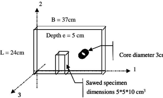
the 19th century. Their dimensions were 37cm * 24cm * 5cm (fig. 3). The manufacturing process and the materials
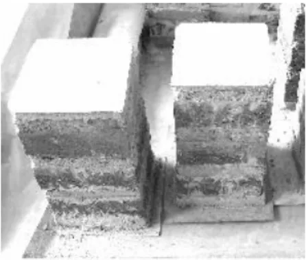
employed make it possible to guarantee a constant quality of the products. A preliminary observation of the bricks allowed assumptions to be made about their behaviour and an experimental method to be defined. A simple observation after sawing lengthwise along the largest plane of the bricks, revealed an internal porosity in layers. In addition, it is important to note that the bricks are worked in a mould, one by one. Clay is deposited in the mould, pressed and surfaced in. It can thus be deduced that the way in which the paste is distributed in the plane of the mould confers identical mechanical properties on the brick in all directions of its plane. We therefore made the assumption that the brick would have transversally isotropic behaviour. So the characterization of the mechanical behaviour of
these bricks, in the elastic domain, was reduced to the determination of five coefficients: two Young's moduli E1 (or
E2) and E3, the G13 shear modulus, and two Poisson's ratios 12, 13 (the axes are defined on fig. 3).
3 Core diameter 3cm dimensions 5*5*10 cm 2 3 Sawed specimen 3 Core diameter 3cm dimensions 5*5*10 cm3 1 3 Sawed specimen Depth e = 5 cm L = 24cm B = 37cm 3 Core diameter 3cm dimensions 5*5*10 cm 2 3 Sawed specimen 3 Core diameter 3cm dimensions 5*5*10 cm3 1 3 Sawed specimen Depth e = 5 cm L = 24cm B = 37cm
Fig. 3 – Brick and sample dimensions
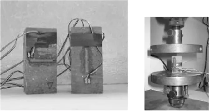
Because there was no standard specifying how to obtain the modulus and the Poisson's ratio of a large solid brick at the time we began our research, we defined our own procedure, by similarity with the tests on mortar described before. We took two types of samples (fig. 4): cylindrical core samples (6 cores, diameter 30mm and height 50mm), to test the behaviour of the bricks perpendicular to their plane, and cuboid samples obtained by sawing (6 samples,
dimensions 5*5*10cm3) to test the behaviour in the plane of the brick (the cores samples have a slenderness lightly
Fig. 4 – Samples before tests, with gauges
The samples were loaded up to a third of their previously measured collapse strength level, at constant speed (0.5 MPa/s for the cuboid samples, 0.2 mm/mn for the cores), these different loading speeds were imposed by our testing machine, but without significant consequences on results due to the non-viscous behaviour of the brick.
3.2 Results on bricks
The compressive strength of bricks reached 22.6MPa in the plane of the brick and 13.8MPa perpendicular to the plane of the brick. In the latter direction, the behaviour was quasi linear up to 50% of the breaking stress (fig. 5). The
Young's modulus E3, in the direction perpendicular to the plane of the brick, was equal to 5500MPa. It was
approximately a third of the E1 modulus, which was taken equal to the E2 (hypotheses) measured at 16700MPa (tab.
4). The Poisson's coefficients were: 12 = 21 = 0.28 13 = 23 = 0.23 (2) 0 2 4 6 8 10 12 14 16 18 -2 -1 0 1 2 3 4
transverse strain axial strain (mm/m)
stress (
M
Pa)
Fig. 5 – Tests on bricks. Results of compression tests on cores
Table 3 – Mechanic behaviour of bricks under compressive stresses (6 samples)
cores 3cm 5*5*10cmsamples 3 Strength (MPa) s.d. fc 13.76 2.39 22.75 3.36 Elastic modulus (MPa) E 5524 16673 s.d. 1415 1727 Poisson’s coefficient =0.08 21=0.28 23=0.23 s.d. 0.02 0.07
Because of the thickness of the bricks (very thin), it was impossible to do tests to find the shear coefficient G13,
(we would have had to cut samples following the bisector of directions 1 and 3). So, we decided to use the empirical
formula, Eq. (3), suggested by Raffard [12], which gave G13=3700 MPa.
1 13 3 1 13 2 1 1 1 E E E G (3)
Finally, the elasticity matrix of the bricks was (stresses in MPa):
13 23 12 33 22 11 13 23 12 33 22 11 σ σ σ σ σ σ 13,4 0 0 0 0 0 0 13,4 0 0 0 0 0 0 7,67 0 0 0 0 0 0 18,1 1,35 1,35 0 0 0 1,35 6 1,67 0 0 0 1,35 1,67 6 ε ε ε ε ε ε 5 10 1 (4)
4 Brick – mortar composite
4.1 Experimental procedure
Two kinds of experimental masonry samples were built at the laboratory: “sandwiches”, which had only horizontal joints of mortar, and “low walls” with horizontal and vertical joints. It should be noted that the brick masonry built in south-west France comprises, in a same structure, joints 1 to 2cm thick.
Before describing the laboratory tests, we should point out that the masonry test procedure proposed by RILEM TC76-LUM [13] was studied. Its recommendations were respected as far as possible (number of bricks and bonds, position of sensors and gauges, immersion of bricks in water, etc.) but, because of the dimensions of our bricks and the low strength of our mortar, not all the procedures were applicable. Because our aim was to establish a relation between the composite masonry and its components, we made efforts to respect exactly the same conditions of work and storage for all the samples, mortar and masonries.
4.1.1 Definition of sandwiches
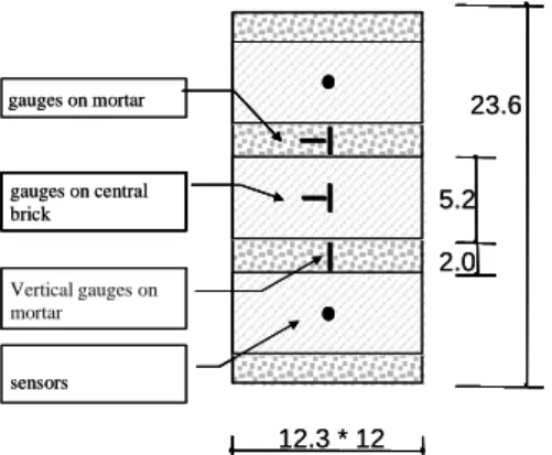
Fig. 6 presents a view of the samples before the tests. The transverse dimensions of the sandwiches and the instrumentation of the samples (ten gauges and two LVDT sensors, 12 samples) are presented in fig. 7. The thickness of the mortar joints was between 1.5cm and 2 cm, this joint final thick dispersion is unavoidable due to the mortar consistency which brings made up difficulties.
2.0 5.2
12.3 * 12
Jauges verticales sur mortier sensors gauges on central brick gauges on mortar Vertical gauges on mortar 23.6 2.0 5.2 12.3 * 12
Jauges verticales sur mortier sensors gauges on central brick gauges on mortar Vertical gauges on mortar 23.6
Fig. 7 – Dimensions of the sandwiches in centimetres
4.1.2 Definition of low walls
The low walls constituted a representative volume of real masonry, for its mechanical behaviour. A preliminary study was necessary to define the geometry of the low walls. Its goal was to define the minimum number of bricks to be set up horizontally and vertically in order to obtain an element behaving like masonry of large dimensions. Thus, the question was to determine the minimum number of blocks beyond which the average mechanical characteristics E and (in the elastic domain) no longer varied. The numerical simulation of a periodic model by the finite element method showed that the variation of the average modulus of the element was lower than 0.1% as soon as the height of the wall exceeded 4 bricks. The number of bricks in the horizontal plane did not influence this result. We chose to build low walls with bases made of only one brick, and 9 bricks high, in order to have a layers number greater than the minimum imposed by the FEM analysis and a slenderness of two. Finally, three low walls were composed of nine thicknesses of bricks separated by mortar joints 1.5cm to 2cm thick (fig. 8). Their height was 61.8cm (and their mass approximately 110kg).
The low walls were built on a strongly reinforced concrete beam, with a higher stiffness than the low wall, then equipped with ten gauges stuck on the large sides (five on each large face) and with four incremental position sensors (LVDT) (one per face). The tests were performed at two months of age.
gauges on mortar sensor
gauges on central brick
gauges on mortar
sensor gauges on mortar sensor
gauges on central brick
gauges on mortar
sensor
Fig. 8 – Geometry of the low walls
4.1.3 Sandwich test results
During the tests, we observed that the collapse of the samples occurred without relative slip between materials. Fig. 9 shows the variation of the average deformation of the sandwiches between the points where the sensors were fixed, according to the stress applied. The behaviour is quasi linear up to approximately 40% of the compressive strength, equal to 8.4MPa (average for sandwiches tested at one month old and two months old).
0 1 2 3 4 5 6 7 8 9 10 0 1 2 3 4 5 6 7 8 9 10 strain (mm/m) st re ss (M P a) essais à 2 mois essais à 1 mois 2 months old 1 month old
Fig. 9 – Behaviour of 1- and 2- month-old sandwiches
The shortening recorded by the sensors made it possible to calculate that the average modulus of the brick/mortar composite with only horizontal joints was about 5200MPa.
The mortar of the bonds maintained its linear behaviour up to its own compressive strength. The sandwich collapsed when the brick broke but the mortar was still plastic. Let us recall here that, in the transverse direction, the brick is three times as stiff as the mortar. Adhesion between bricks and mortar, observed during the tests, created a confinement effect on the mortar which delayed its failure. The great transverse deformations of the mortar generated the collapse of the bricks. Interface strength between the two materials played a fundamental role in the strength of the composite material. This strength was improved by the roughness of the bricks, which were moulded with sand, and the fact that they were immersed in water before assembly.
4.1.4 Low wall test results
The elements tested included horizontal joints and a vertical joint. Three low walls were built. We give only the most significant results here. The cracking of a specimen developed without apparent slip between the mortar and
brick. The compressive strength fc of the low wall tested was 10.2MPa (tests at 2 months old). The behaviour of the
bricks was quasi linear up to approximately 7MPa, i.e. approximately 70% of the strength of the low wall. Tab. 4 allows comparison with the other tests. The shortening between the sensors allowed us to calculate the average modulus indicated in tab. 5.
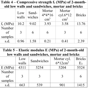
Table 4 – Compressive strength fc (MPa) of
2-month-old low walls and sandwiches, mortar and bricks
Low
walls wiches
Sand-Mortar 4*4*16 cm3 Mortar cyl.6*12 cm2 Bricks fc (MPa) 10.2 9.02 3.93 3.58 13.76 Number of samples 3 6 6 3 6 s.d. 0.96 1.58 0.21 0.41 2.39
Table 5 – Elastic modulus E (MPa) of 2-month-old low walls and sandwiches, mortar and bricks
Low
walls Sandwiches Mortar cyl. 6*12cm2 Bricks E
3 E (MPa) 4311 5254 5204 5524 Number of samples 3 3 3 6 s.d. 663 539 901 1415
4.2 Masonry computer model
The aim was to choose a model and to calibrate its parameters for a macro element able to describe the mechanical behaviour of the homogenised masonry in elastic domain until the compressive strength (the tensile strength being reported to the interface element described later).
The question here was to choose the most sufficient model considering the results of the tests carried out in the laboratory on the composite elements, sandwiches and low walls. The following three theoretical models were considered: elasto-plastic model with hardening and Von Mises criterion (model 1), elasto-plastic model without hardening and a Drucker-Prager criterion (model 2), and non linear elastic damage model (Mazars [9] - model 3).
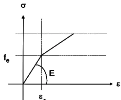
Model 1 is described for compressive stress by fig. 10, and model 2 by fig. 11. They contain a hardening domain.
Elastic limit fe and elastic strain c were determined by numerical simulation.
fe fc E c e fe fc E c e
Fig. 10 – Model 1: elastic plastic model with Von Mises criterion
fe E e fe E e fe E e fe E e fe E e fe E e fe E e fe E e e
Fig. 11 – Model 2: elastic plastic model with Drucker-Prager criterion
The Drucker-Prager criterion seems to better describe material, like mortar and bricks, with very low tensile strength. It uses a shear angle chosen according to the test results without exceeding 35°. Beyond this value, according to Desrues [4], the model is not exact.
Model 3 uses damage theory, which is a way to describe the non-linear material that is different from the plasticity theory. A damage parameter D is defined to change the elastic modulus E of the stressed material Eq. (4).
ED = E (1 – D) (4)
The stress – strain relation is given by
= E (1 – D) (5)
The Mazars model (fig. 12) is applicable to elastic isotropic material. As explained above only the compressive
damage Dc is used herein.
Bc ko
c c o c e A A 1 k 1 D (6)2 3 2 2 2 1 (7) i > 0 in extension If i < 0 then i 0 else i i, i = 1, 3.
ko is the initial damage threshold. Ac and Bc are found by experimental tests.
Two steps were necessary to select the model. First, the theoretical parameters were adjusted in conformity with the test results carried out on basic materials, brick and mortar, individually. The parameters are given in tab. 7 and the curves in fig. 12 - 15.
Table 6 – Parameters of the 3 selected models
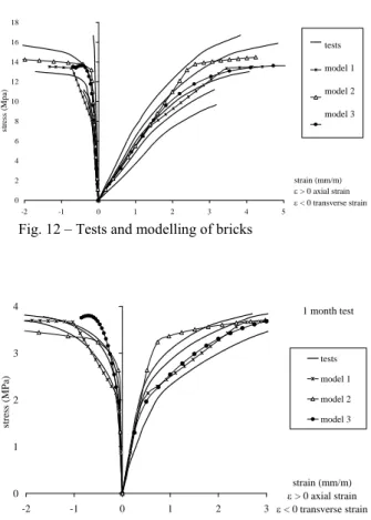
Model 1 « Von-Mises» Model 2 « Drucker – Prager» Model 3 « Mazars » Mortar E=5204 MPa = 0.17 fc = 3.7 MPa fe / fc = 0.55 c = 2.5 %o = 30° fc = 3.7 MPa fe / fc = 0.85 k0 = 0.8E-4 Ac = 0.3 Bc = 1000 = 1 Brick E=5524 MPa 23 = 0.23 fc = 13.8 MPa fe / fc = 0.55 c = 3.5 %o = 25° fc = 13.8 MPa fe / fc = 1 k0 = 1.8E-4 Ac = 1.2 Bc = 2000 = 1 0 2 4 6 8 10 12 14 16 18 -2 -1 0 1 2 3 4 5 strain (mm/m) > 0 axial strain < 0 transverse strain st re ss ( M pa ) essais modèle 1 modèle 2 modèle 3 tests model 1 model 2 model 3
Fig. 12 – Tests and modelling of bricks
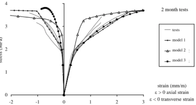
1 month test 0 1 2 3 4 -2 -1 0 1 2 3 strain (mm/m) > 0 axial strain < 0 transverse strain stress ( M Pa) tests model 1 model 2 model 3
2 month tests 0 1 2 3 4 -2 -1 0 1 2 3 strain (mm/m) > 0 axial strain < 0 transverse strain st re ss ( M P a) essais modèle 1 modèle 2 modèle 3 tests model 1 model 2 model 3
Fig. 14 – Tests and modelling of 2-month-old lime mortar
0 1 2 3 4 5 6 7 8 9 10 11 -3 -2 -1 0 1 2 3 4 strain (mm/m) > 0 axial strain < 0 transverse strain str ess ( MPa ) tests model 0 1 2 3 4 5 6 7 8 9 10 11 -3 -2 -1 0 1 2 3 4 strain (mm/m) > 0 axial strain < 0 transverse strain str ess ( MPa ) tests model
Fig. 15 – Tests and modelling (model 1 only) of lime mortar after carbonation
Secondly, the parameterized behaviour laws were integrated in a finite element numerical calculation reproducing the tests performed on the sandwiches and the low walls. The choice of the best model among the three models selected was made by comparing the numerical stress-strain curves of the composites with the experimental tests (2-month-old specimens, fig. 16 - 17). Differences appeared only in the non-linear phase, of course, i.e. beyond 3MPa.
It should be noted that the three theoretical models are markedly different in the mortar plastic domain. The tests clearly show a break in the stress-strain curve around a stress equal to 3.2MPa at 1 month old or 4.5MPa at 2 months old. The average of these two values is 3.85MPa, which should be compared with the strength measured on the mortar sample: 3.7MPa.
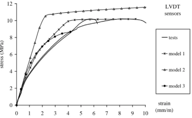
LVDT sensors 0 2 4 6 8 10 12 0 1 2 3 4 5 6 strain (mm/m) stress ( M Pa) tests model 1 model 2 model 3
LVDT sensors 0 2 4 6 8 10 12 0 1 2 3 4 5 6 7 8 9 10 strain (mm/m) stress ( M Pa) tests model 1 model 2 model 3
Fig. 17 – Behaviour of 2-month-old low walls
The behaviour observed above the mortar compressive strength is correctly described by model 1, the “Von Mises” elasto-plastic model, and model 3, the “Mazars” elastic damaged model. But the latter regresses slowly, with a long computation time. This is a major disadvantage when the aim is to calculate a whole bridge. In conclusion, model 1, the elastic plastic model with a tri-linear behaviour law associated with a Von Mises criterion, was adopted. Tab. 7 and fig. 18 synthesize the values and the model.
0 3 6 9 12 15 -2 -1 0 1 2 3 4 5 strain (mm/m) > 0 axial strain < 0 transverse strain stress ( M Pa)
modèle brique seule
modèle maçonnerie
modèle mortier seul
brick model masonry model mortar model
Fig. 18 – Mechanical behaviour of brick masonry under compression failure (model 1 accepted, Von-Mises criterion)
Table 7 – Parameters of accepted model (Von-Mises criterion)
brick accelerated ageing mortar with masonry
E (MPa) 5524 7777 6810
0.23 0.15 0.13
fe / fc 0.55 0.55 0.5
fc (MPa) 13.8 9.7 12
c (mm/m) 3.5 2.5 3
5 Study of interface between brick and mortar
The theoretical behaviour described previously, associated with the massive finite macro-elements in the computer code, is usable in elastic domain but supplies only the compression strength: the tensile strength being reported to the interface elements where the tensile cracking effects by tension or shearing must be modeled. For that purpose, interface elements following a Coulomb type yield criterion, are used.
friction angle (close to 50°). The tension strength, obtained by extending the Coulomb line in the tension domain, was about 0.06MPa. 6cm 3cm 6cm 2cm 6cm 3cm 6cm 2cm
Fig. 19 – Specimen dimensions used to characterize the Coulomb model
0,0 0,5 1,0 1,5 2,0 -0,2 0 0,2 0,4 0,6 0,8 1 1,2 1,4 (MPa) t (MPa) 0,11+ sigma tan(49,5°) two months old tests one month old tests
Fig. 20 – Coulomb criterion
Table 8 – Characteristics of the brick-mortar interface
Cohesion Shear angle Tensile strength
0.1MPa 49° 0.06MPa
Regression coefficient : R2=0.96
6 Conclusion
An experimental study was carried out to describe the mechanical behaviour up to collapse of solid bricks
moulded with hydraulic lime mortar similar as it was used in the 19th century. We observed, for these two materials, a
linear elastic domain up to 40 to 50% of the collapse load. A model is proposed, integrating the elastic phase and the plastic hardening domain until compressive collapse through an elasto-plastic macro-element, and an interface element able to model the shear and tension failures. The compressive strength of brick-lime mortar masonry is around 12 MPa. In a bridge FEM analysis, it is necessary to integrate both macro element and interface element which takes into account the possibilities of local ruptures by cracking (rupture in tension and shear). These last elements represent the interface between the blocks and the mortar. We have determined the interface criterion for solid moulded bricks and hydraulic lime mortar. Our modelling, made by assembling elasto-plastic homogenized macro elements bound by tensile brittle interface, can be surely used to analyse others masonry works using similar materials.
7 Acknowledgments
References
[1] Cecchi, A., Sab, K., “A multi-parameter homogenization study for modeling elastic masonry”, European Journal of Mechanics, A/ Solids 21, 2002. pp. 249-268.
[2] Cecchi, A., Sab, K., “Out of plane model for heterogeneous periodic materials: the case of masonry”, European Journal of Mechanics, A/ Solids 21, 2002. pp. 715-746.
[3] Cruz-Diaz, J.I., Etude des murs de contreventement en maçonnerie d’éléments de terre cuite, PhD thesis, Marne-la –Vallée University, 2002.
[4] Desrues, Jacques. Limitations du choix de l’angle de frottement pour le critère de plasticité de Drucker-Prager, laboratoire 3S, Revue Française de Génie Civil n°6, 2002, COSS’01, pp. 853-862.
[5] Domède, N., Méthode de requalification des ponts en maçonnerie, PhD thesis, INSA de Toulouse, 2006, 202p.
[6] EN 1992-1-1, Eurocode 2, Calcul des structures en béton - Partie 1-1 : règles générales et règles pour les bâtiments, Oct. 2005. [7] Lanas, J., et al., “Mechanical properties of natural hydraulic lime-based mortars”, Cement and concrete research, 34, USA,
2004, pp. 2191-2201.
[8] Lourenço, PB., Computational strategies for masonry structures. PhD thesis, Delft University of Technology, 1996.
[9] Mazars, Jacky., Application de la mécanique de l’endommagement au comportement non linéaire et à la rupture du béton de structure, PhD thesis, Université Paris 6, 1984.
[10] Pande, N., Liang, J.X., Middleton, J., “Equivalent elastic moduli for brick masonry”, Computers and Geotechnics, vol. 8, n° 3, 1989, pp. 243-265.
[11] Pegon, P., Anthoine, A., "Numerical strategies for solving continuum damage problems with softening. Application to the homogenization of masonry”, Computers and structures, vol. 64, issues 1-4, July-Aug. 1997, pp. 623- 642.
[12] Raffard, Delphine., Modélisation de structures maçonnées par homogénéisation numérique non linéaire, application aux ouvrages d’intérêt archéologique. PhD Thesis of INPL, Vandoeuvre les Nancy, INP de Lorraine, Dec. 2000, 206 p.
[13] RILEM. ‘Test for masonry materials and structures’, Materials and structures, Vol.21, July 1998, pp. 363-377.
[14] RILEM TC14-CPC, ‘Concrete test methods. Measurement of deformation under compressive load’, Materials and Structures, vol. 16 , N° 91, 1983.
[15] SETRA / LCPC. Les ponts en maçonnerie, historique, stabilité, utilisation du programme VOUTE, 1982.
[16] Van Balen, K., Van Gemert, D., “Modelling lime mortar carbonation” in Materials and structures, vol. 27, number 7 / August 1994, pp. 393-398.
![Fig. 2 – Relative strength increase of lime mortars as function of time – comparison with literature data [7]](https://thumb-eu.123doks.com/thumbv2/123doknet/14275821.490969/4.892.70.492.219.740/fig-relative-strength-increase-mortars-function-comparison-literature.webp)